ChristopheFR said:
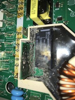
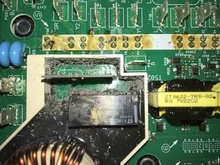
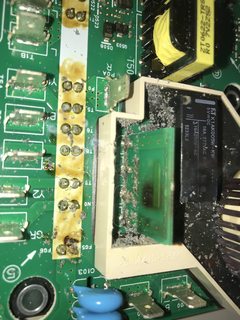
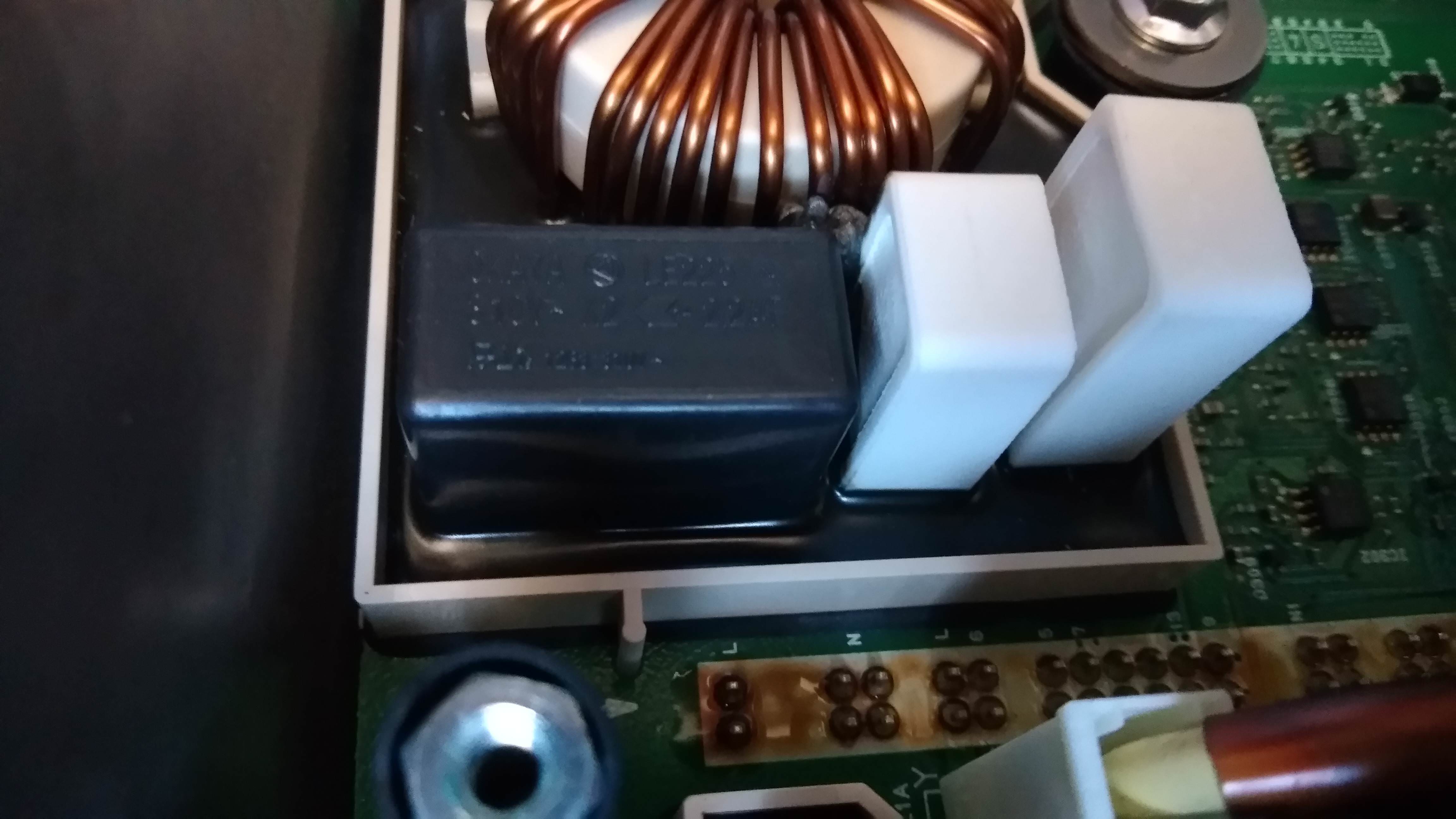
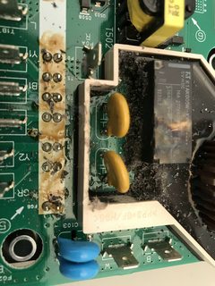
We see traces on the cover, I think it is not due to a short circuit, but just a significant heating of the material just below.
It looks like this discoloration is common, sadly.
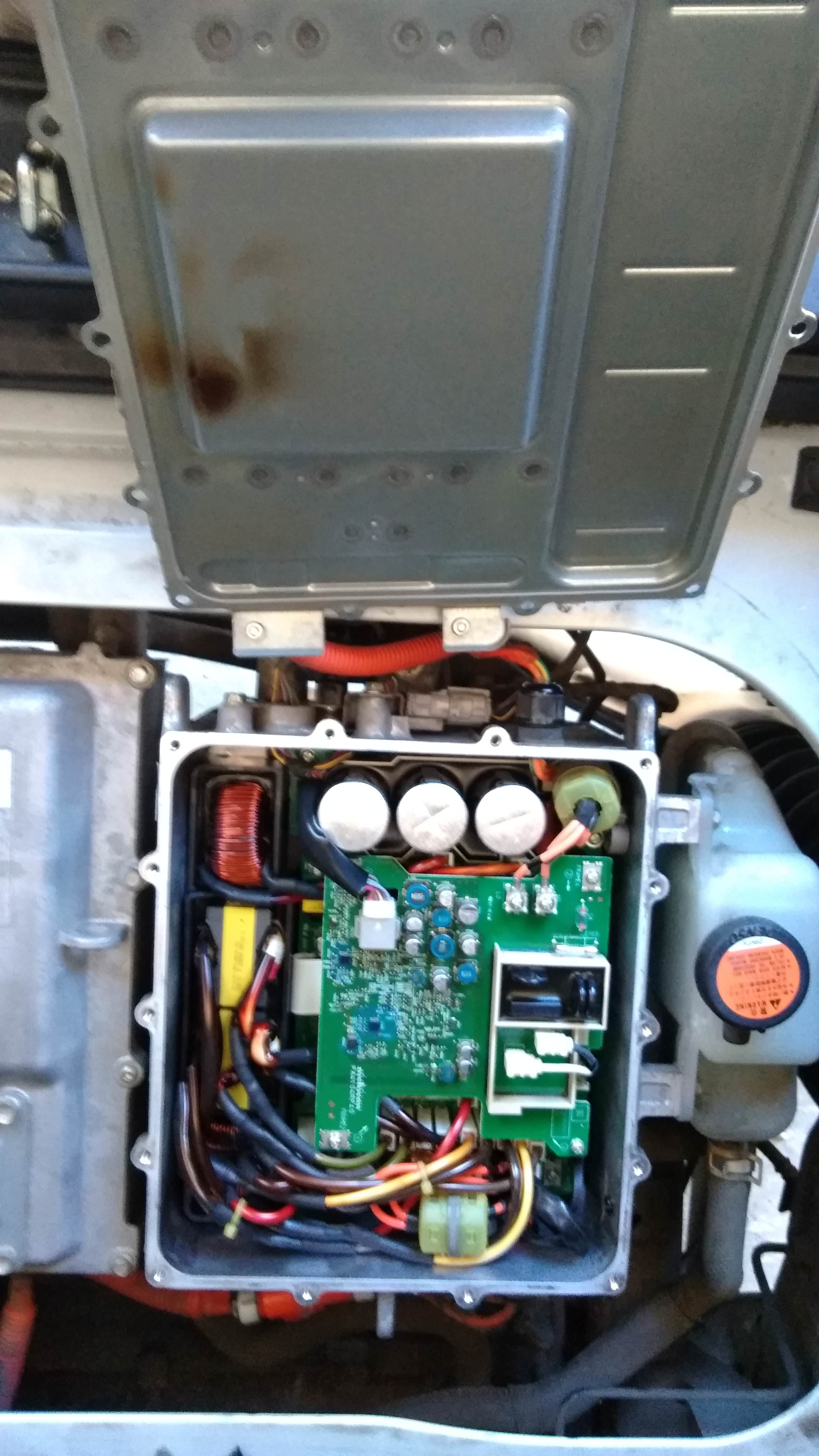
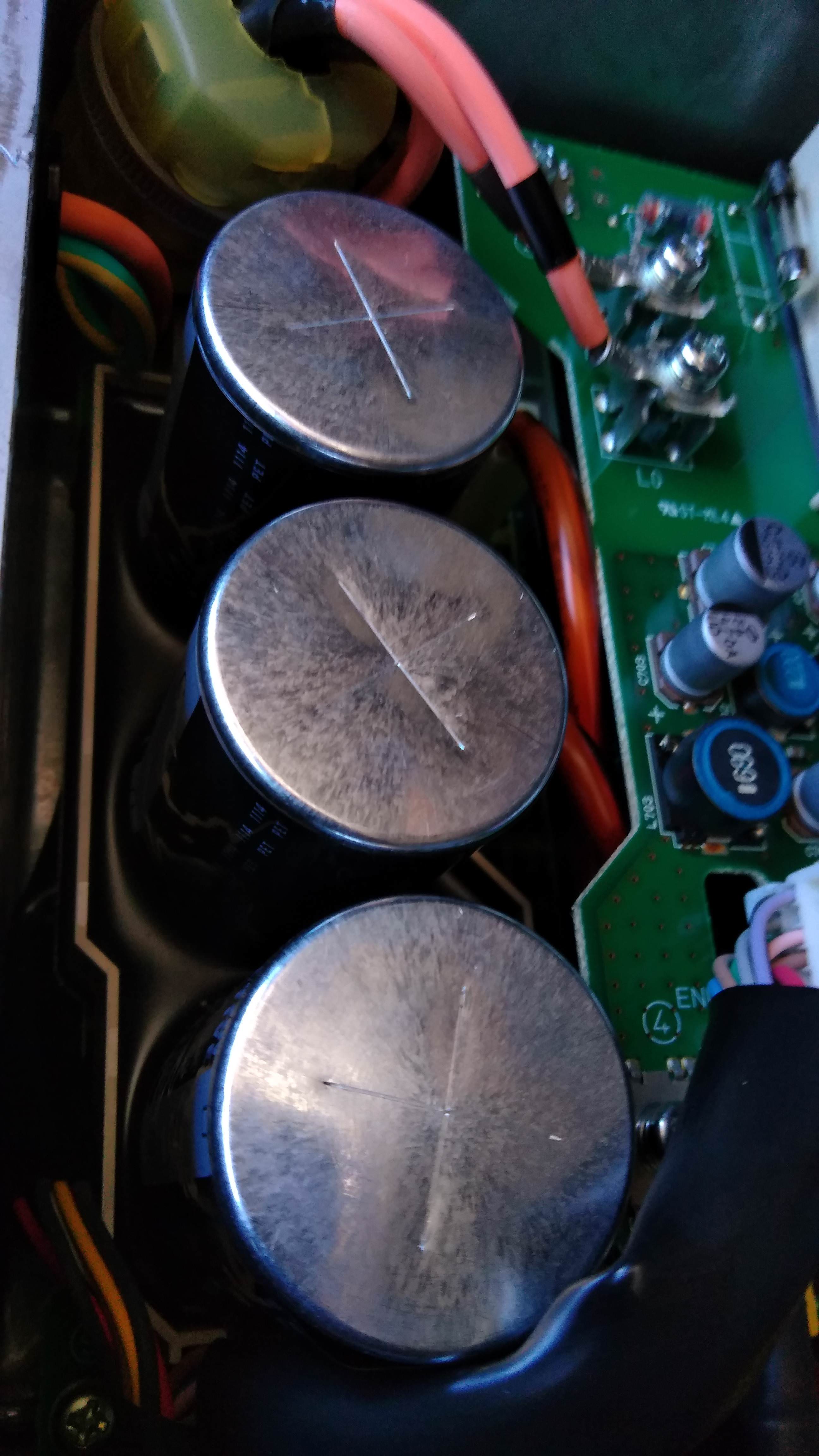
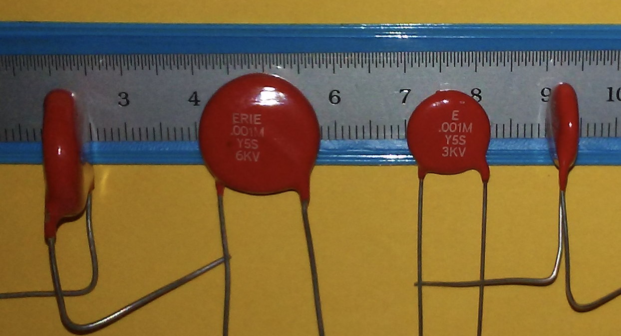
1 of the three capacitors is inflated on the top. Are the other two still in good condition?Do you think it is better to change the 3 pieces?
Difficult to see in your photo. Presuming that one really is bad, then yes I would replace all three.
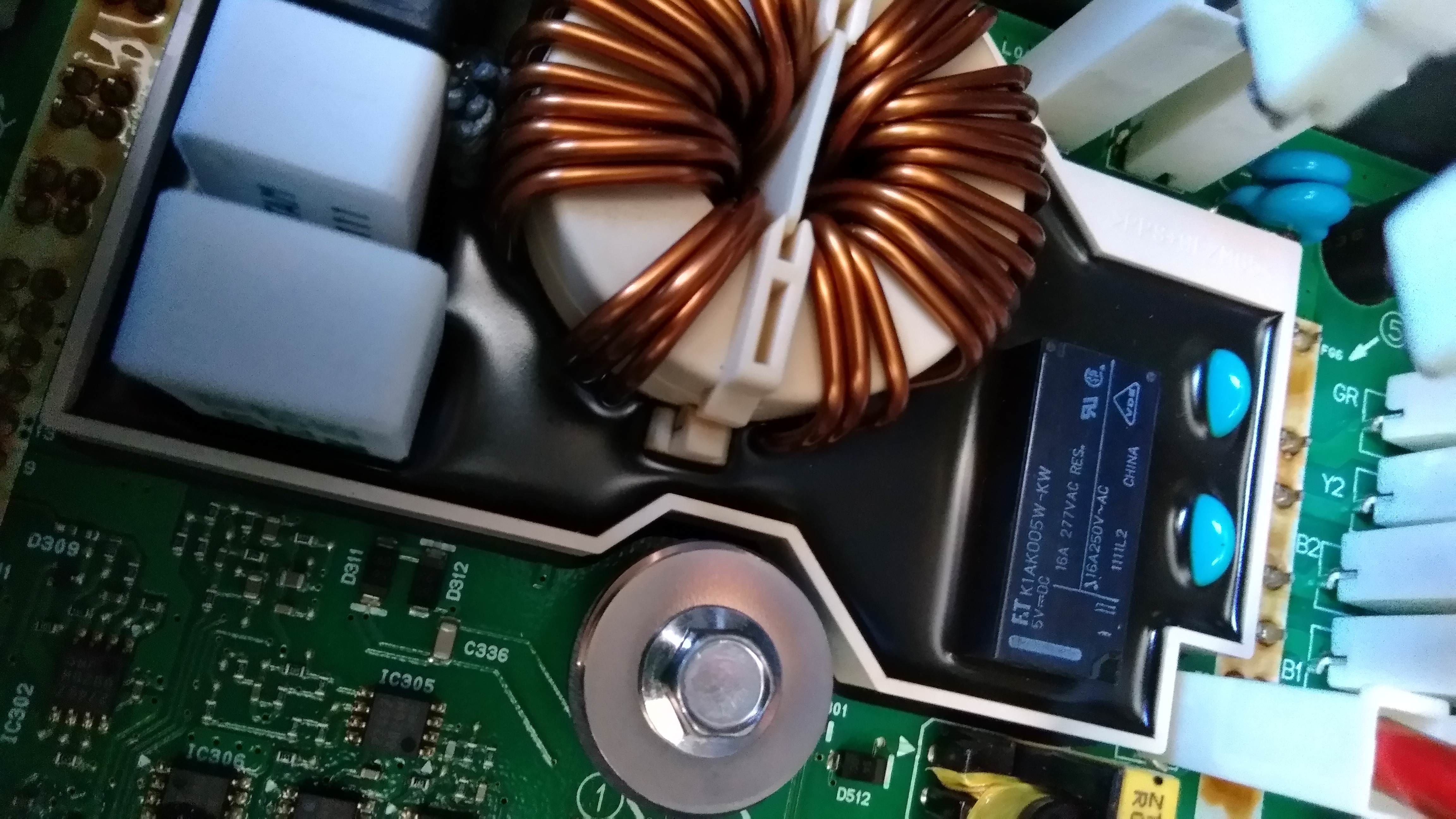
The two resistors 4.7 ohm seem in good condition, there is no trace of burn.
Ditto for the two blue capacitors
Yes, unlike many charrgers so far. But the 4.7 Ω resistors may still be bad, see below.
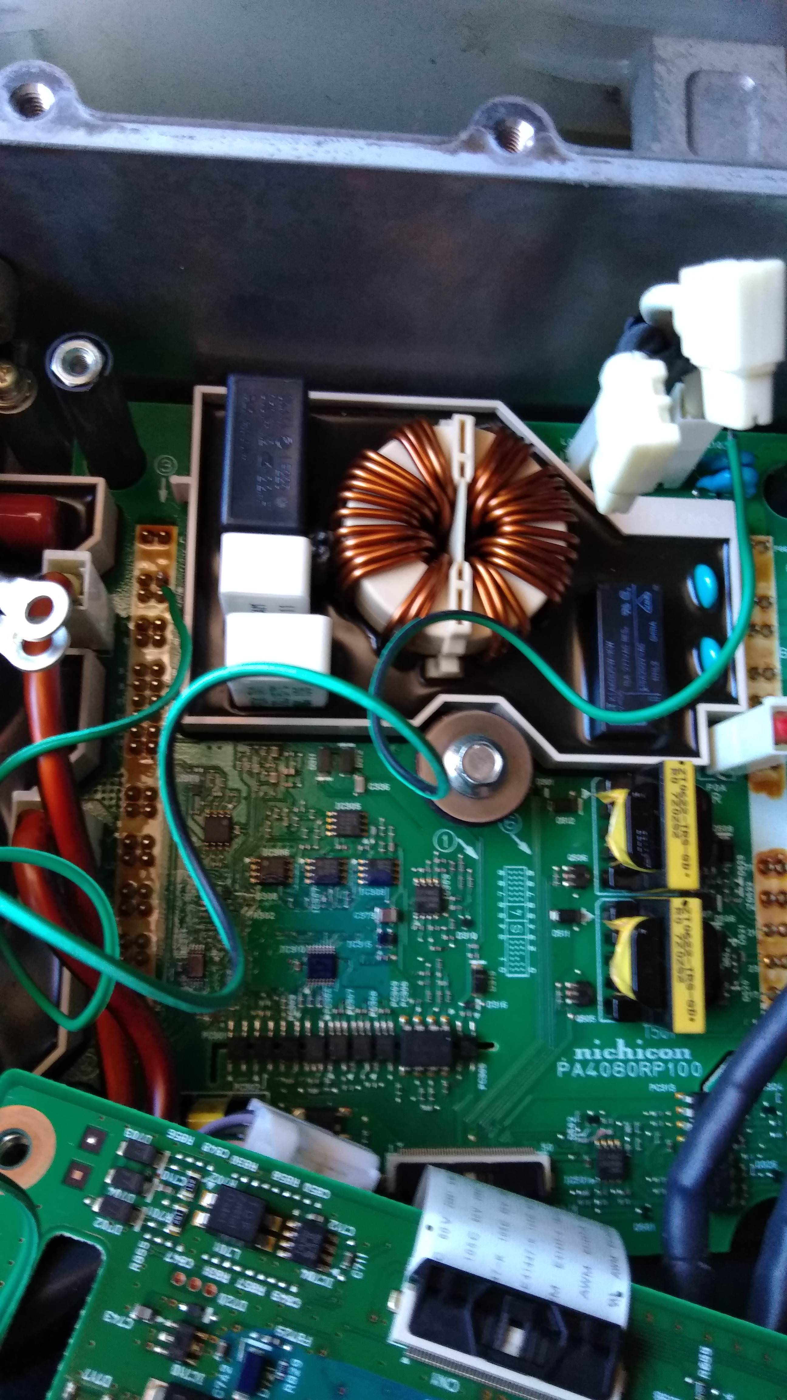
Is this a correct connection for my ohmmeter (green wires)?
It looks right to me, but others please chime in.
and there, result: my ohmmeter reads 0L, no resistance.
Actually, "OL" represents OverLoad, which is
infinite resistance, i.e. zero conductivity. Either one of the 4.7 Ω resistors is open circuit, or the test isn't valid. Energising the relay will hopefully show which.
Is it the larger resistor that fused?
They are in series. So it's not possible to tell which one failed, or possibly both.
due to overcurrent or overvoltage? No apparent damage on this resistors!
It's certainly unusual. Unless the resistors somehow saw 240 V across them; in that case, the fuse inside one of them would blow quickly, before the resistors overheated and discolored.
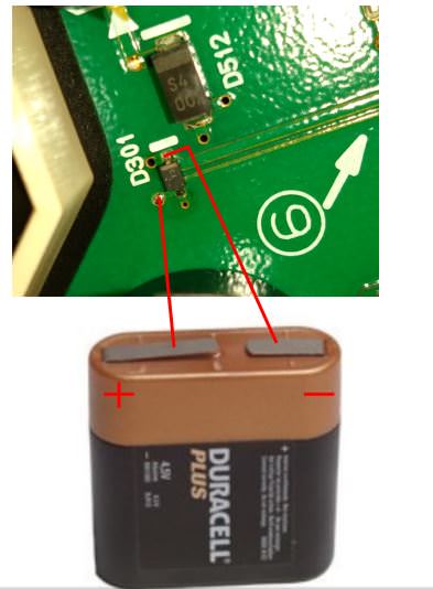
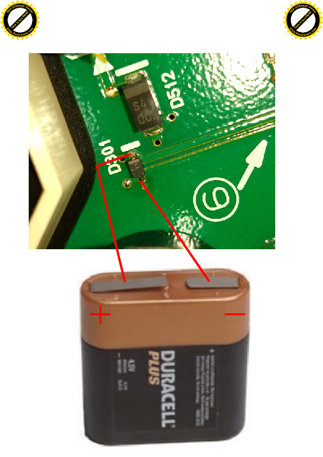
Skylogger, do you think for the second test with 5 volts on the terminals of diode D301, that a 4.5volt battery like this one is enough to carry out the test?
That battery should be fine.
Is this correct for the wire connections?
NO! The stripe (on the diode and also on the silk screen overlay of the printed circuit board) is for the cathode of the diode, which is the negative end
if you want the diode to conduct. But in this case, with no current limiting, we
don't want the diode to conduct, except briefly as the power is removed from the coil. This gives a path for the current to continue flowing after the battery is disconnected, so there isn't a large voltage spike that could damage the other electronics (though the other electronics on the upper board should be disconnected for this test). [ Edit: so you need to reverse the battery compared to your photo; battery positive to stripe on diode; battery negative to non-stripe end of diode. ]
With the relay energized, you should see much less resistance across your green wires, reading "0.0" or perhaps "0.2" due to the resistance of the multimeter leads and green wires.
If you don't see this, and it remains at "OL", then either one of your resistors is open circuit
and the relay contacts are open circuit as well, or your green wires aren't right. Another possibility is blown PCB tracks or badly soldered quick connects (etc), but these seem very unlikely.
what do you think of this failure? A problem due to a storm?
I think it's too early to tell.
A problem due to the capacitor that has inflated?
I don't think so. Those three large capacitors only work at 100 or 120 Hz, not at several kilohertz switching frequency. So they can degrade a little and still perform adequately. If they went low capacitance, there would be higher than normal 100 or 120 Hz ripple on the ~400 V DC bus, but I don't see that causing the pre-charge resistors to open circuit.


