The Troubleshooting and Repair for On-board Charger (OBC) Thread

Mitsubishi i-MiEV Forum

Help Support Mitsubishi i-MiEV Forum:

This site may earn a commission from merchant affiliate links, including eBay, Amazon, and others.
skylogger said:
On the second OBC that I just finished working on, I've been told that the charging failed during a night that there was a storm and heavy rain. This could point towards a blackout, brownout, or power surge as the source of the falult.

Just playing catch up on this thread, haven't had a chance to look at our OBC, and only received the replacement caps on Monday, so I intend to work on it over this weekend. Still waiting on the fuse from Mitsu though.

Interesting @skylogger, this could be the cause. When we had the failure with our iMiEV we had it connected to our charger connected to the off-peak circuit of the house (since moving we no longer have off-peak, we have solar/batteries instead, but I degrees). So in our situation the fault is likely to have occurred when it was charging that night (it was fine the night before obviously), the power would have turned on sometime between 12am and 1am, and then turned off again sometime between 5am and 7am. This may have caused our failure, as it is a dead cut from before the EVSE. It is an interesting theory that is for sure.

As for the fuse, would this work?

https://au.rs-online.com/web/p/prod...Op2rdwHPg-NR5KHvu2hoC0T4QAvD_BwE&gclsrc=aw.ds
 
coulomb said:
They are 1 nF (1000 pF) 3150 V capacitors, as specified in this post: Murata DEHR33F102Kppp .

Whether they should be replaced with something "stronger" is debatable, but you are unlikely to find a higher DC voltage rating.

Does anyone have suggestions on where to buy quality capacitors (I'm in the USA)?

A quick search on eBay shows there are capacitors rated up to at least 40kV. Would a 1000 pF, 15 KV "Cera-Mite" capacitor be a bad idea? Are all capacitors from eBay a bad idea?
 
electronpusher said:
Electrically, yes it would work, and it seems to have very roughly similar "speed" (it's hard to tell, because the original fuse has very wide times for blowing at a particular current).

But you'd want the "bolted contacts" version of that fuse, which unfortunately none of the regular parts suppliers seems to stock. Even if you found that, the bolts are 45 mm apart, and the holes in these would be 50.6 mm apart. So you'd have to enlarge the slots.

The best I came up with is in this post. It's also a photovoltaic 38x10 mm fuse (the original is a non-standard 31x7.2 mm), but with the bolted contacts, and the holes are 51 mm apart. So again, you'd need to enlarge the slots. The Australian version of the Mouser URL for this part is https://au.mouser.com/ProductDetail/Bussmann-Eaton/PV-20A10-T?qs=sGAEpiMZZMvnfWYzRsH6EbYZ2445BpOV . It's almost expensive enough to get free shipping; add something inexpensive to the order to qualify for free shipping (AU$45 minimum order). Something I ordered recently from Mouser took 6 calendar days to arrive (to an Eastern capital city address).
 
Quixotix said:
Does anyone have suggestions on where to buy quality capacitors (I'm in the USA)?
I'd try the "usual suspects": Mouser, Digi-Key, Newark.

A quick search on eBay shows there are capacitors rated up to at least 40kV.
I meant to say "in a similar sized package". Though I see that some of the Vishay capacitors go to 7.5 kV. They are a bit thicker than the originals, but there seems to be room in there for somewhat larger capacitors.

Would a 1000 pF, 15 KV "Cera-Mite" capacitor be a bad idea?
There is quite a large range; the name "Cera-Mite" seems to cover all Vishay's ceramic capacitors. Some are rated at only 1000 VDC; I think we'd want at least 3000 VDC rating to be no worse than the originals. The originals and therefore the PCB holes have 7.5 mm spacing. You can of course bend the leads to a certain extent to accommodate other lead spacings. I think that a 15 kV rating is way more than is needed.
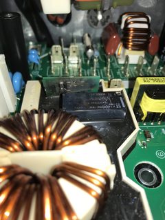
From the "R" in the series name, I'm guessing that these use the X7R ceramic formula. These are among the worst for non-linearity and variation of characteristics with temperature. I wonder if we'd be better off with some sort of film capacitor. Of course, film capacitors can have higher inductance.

Are all capacitors from eBay a bad idea?
It's a highly mixed bag. As long as they are genuine branded components, not some knock-off designed to look like branded parts, then I don't see a problem.
 
Quixotix said:
Did anybody notice what the Murata data sheet says about these DEH series capacitors:
...
Do not use these products in any automotive
power train or safety equipment including battery
charrgers for electric vehicles
and plug-in hybrids. ...
(My altered boldness)
I think I did notice that in passing, but it didn't occur to me that perhaps this is the Root Cause (or one of them). Perhaps these are just the wrong capacitor to use in an automotive environment.

I guess we use them anyway because there isn't a better option?
I think we could find a better option, designed for automotive applications.

Do you think it was our MIEVs that caused this statement to be included?
I think that's a bit of a stretch. Possible, I suppose. It's not a good look for Murata that their parts turn up exploded in vehicle charrgers.

The 3 empty boxes (or ppp) at the end of the part number are where the code letters for the lead style...
Thanks.
 
coulomb said:
From the "R" in the series name, I'm guessing that these use the X7R ceramic formula. These are among the worst for non-linearity and variation of characteristics with temperature.
Hmmm. I take it back. From the Murata Capacitor Data Book, the R series (among two others) has a quite moderate and at least linear change of capacitance with temperature. There are plenty series that look a lot worse.

Also. the only series that seems to be rated for automotive use is only rated at 300 VAC. Not much use for putting across essentially a 360 VDC battery rail.

So maybe the original isn't so bad, but I still think we could find a better replacement.
 
The safety caps in my box, HR R 102K 2KV, are 9mm in diameter and only rated 2kV.

The MuRata catalog datasheet (C85E.pdf) i found from Newark doesn't have the restriction about EV charrgers, but it has a date code of 06.6.1, whereas the restricted version datasheet was dated March 28, 2018.

So i think that yes the experience of the Miev chargger may have caused them to add this statement.

But still what is causing the massive overvoltage to blow these caps?

p.s. Quixotix, your 220uF output filter Cap looks like it has gotten hot and caused the sleeve to shrink and uncover the top--may want to check/replace if high ESR.
 
Thanks Coulomb and Kiev.

kiev said:
p.s. Quixotix, your 220uF output filter Cap looks like it has gotten hot and caused the sleeve to shrink and uncover the top--may want to check/replace if high ESR.

Can I do this with a multimeter? I have a decent multimeter, but not much more for testing electronics.

That capacitor seems to have 3 terminals. If a multimeter will work, what resistance values would be good or bad? Between which of the 3 terminals? I assume I'd need to remove the capacitor from the circuit board?

Note: It's possible the sleeve on the 220uF capacitor was short originally. The sleeve slides up and down freely and I know I moved it before I took the picture. The sleeves on the 680uF capacitors cover the crimp area of the can, and have wrinkles in this area. The sleeve on the 220uF capacitor has no wrinkles and doesn't appear to have covered the crimp area originally.
 
Electronpusher: When I ran into problems getting the original 20 amp fuse, I bought the 10x38 fuse type that you showed in your last post.
To be able to use it, I also bought a DIN fuse holder, and ran wires from the fuse holder with small ring terminals that would screw down to the original two screw terminals that the tabs on the original fuse mounted to. You posted link to RS. you might check if RS sell 10x38 fuse holders like this:
https://au.rs-online.com/web/p/rail-mount-fuse-holders/7686134/


QUIXOTEX: From your description of your 12v AUX battery, it sounds like during the last run, the 12v battery was also not getting charged.
You will probably also need to check the 20 amp fuse that is located in the top of the MCU (Motor Control Unit)
You will see a small hatch/lid on top of the main cover on the MCU which is the other big box just to the right of the charger.
If you open that compartment you will see the 20 amp fuse inside . If you check that, you might find that blown, which has been quite common
with these charger faults. Once you clear away the rubbery potting around the blown cap, you will probably find remaining leads still coming up from the PCB holes. If like coulomb said, you are quick with soldering, you can attach the leads of a new cap to these remaining leads of the old cap, so you do not have to do rework from bottom of PCB and remove the waffle. I bent the leads into hook shapes, and joined. If you want to replace the other cap that did not get vaporised, just crush it with pliers so it crumbles except leaving its leads coming up from the PCB. then join a new cap to the old leads. After getting these caps replaced and checking the 20 amp fuse, I would run through the process of checking the 2x 4.7 R resistors and the relay by going through the test procedure I listed earlier in this thread.
 
skylogger said:
it sounds like during the last run, the 12v battery was also not getting charged.

You are right. It was not getting charged.

You will probably also need to check the 20 amp fuse that is located in the top of the MCU (Motor Control Unit).

The dealer replaced a "high voltage fuse" (a $100 part). Is this likely the fuse you are talking about? Is it likely that it the new fuse blue again when the dealer was testing the car?

just crush {the capacitor} with pliers so it crumbles

Thanks for the tip.

I would run through the process of checking the 2x 4.7 R resistors and the relay

I'll look that up. Thanks
 
Quix: It sounds like the dealar has changed out the fuse but it may have blown again since they did not fix what causes the fuse to blow.
You cannot just look at the fuse to see if it's blown, because the fuse is filled with sand. You have to use an ohm meter and check for close to zero ohms for a good fuse. Make sure car is shut down so no voltage is running through the fuse when testing.
The Dealership price of a fuse here in Australia is $AU25, so your $US100 Price probably included the labour cost to fit it.
 
coulomb said:
electronpusher said:
Electrically, yes it would work, and it seems to have very roughly similar "speed" (it's hard to tell, because the original fuse has very wide times for blowing at a particular current).

But you'd want the "bolted contacts" version of that fuse, which unfortunately none of the regular parts suppliers seems to stock. Even if you found that, the bolts are 45 mm apart, and the holes in these would be 50.6 mm apart. So you'd have to enlarge the slots.

The best I came up with is in this post. It's also a photovoltaic 38x10 mm fuse (the original is a non-standard 31x7.2 mm), but with the bolted contacts, and the holes are 51 mm apart. So again, you'd need to enlarge the slots. The Australian version of the Mouser URL for this part is https://au.mouser.com/ProductDetail/Bussmann-Eaton/PV-20A10-T?qs=sGAEpiMZZMvnfWYzRsH6EbYZ2445BpOV . It's almost expensive enough to get free shipping; add something inexpensive to the order to qualify for free shipping (AU$45 minimum order). Something I ordered recently from Mouser took 6 calendar days to arrive (to an Eastern capital city address).

Thanks coulomb, just want to source some alternative fuses if the OEM become difficult to obtain. Work on ours starts tomorrow.
 
skylogger said:
Electronpusher: When I ran into problems getting the original 20 amp fuse, I bought the 10x38 fuse type that you showed in your last post.
To be able to use it, I also bought a DIN fuse holder, and ran wires from the fuse holder with small ring terminals that would screw down to the original two screw terminals that the tabs on the original fuse mounted to. You posted link to RS. you might check if RS sell 10x38 fuse holders like this:
https://au.rs-online.com/web/p/rail-mount-fuse-holders/7686134/

Thanks skylogger, I might get a couple of those, at lest I can test while waiting for the OEM fuse.
 
So with these non OEM fuses, does anyone think it would be doable to convert the fuses without screw terminals into fuses with screw terminals by soldering the fuse to some copper fashioned into screw terminals and soldering the fuse to the copper?
 
electronpusher said:
So with these non OEM fuses, does anyone think it would be doable to convert the fuses without screw terminals into fuses with screw terminals by soldering the fuse to some copper fashioned into screw terminals and soldering the fuse to the copper?
I doubt it. Fuses are inherently thermal in nature; soldering those big end caps requires a lot of heat. I think you'd destroy the fuse; I've destroyed several trying to do just that. But they were 3AB (same size as 3AG but ceramic). Those fuses all ended up high resistance or open circuit. A 10x38 mm fuse is a bit bigger, so it might work, but it's a big gamble. They're expensive enough (to me) that you likely wouldn't want to buy a few spares and experiment.

Hacking the Mouser fuse, which already has bolt-on connections, is a different matter. You can reshape the tags without heating up the fuse proper to any great degree.

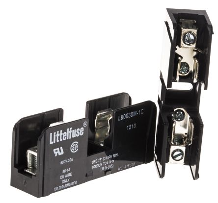
If you're set on using the 10x38 mm fuse without the bolt-on tags, you might be able to find smaller, cheaper, non-DIN rail mount fuse holders that should be easier to find space for. Edit: such as this one.

F3607272-01.jpg


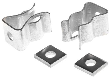
Or you could solder or screw to these sorts of clips, but it would be awkward making it safe and reasonably vibration-proof.

F2474071-01.jpg
 
Hi All

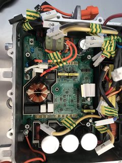
Open heart surgery on our iMiEV has begun. I have opened up the OBC, removed the top board, and removed all the screws that I know of that hold the middle board (with the blown caps) from the OBC, but it will not budge (with light force), and I am too afraid to apply too much force, because I assume there is something else holding this down.

So, how do I remove the middle board? Is there screws in the underside? Is it because of the waffle plate, and therefore takes a little force. Do I need to rub my tummy, tap my head while standing on one foot to pull it out.

Thanks for your help.

nocCJDHm.jpg
2ZnfMZZm.jpg
 
Hi Electronpusher: From the photo you just posted, it looks like you have all the screws removed, but have not unscrewed/removed the four hex standoffs. Even though it looks like the standoffs do not make contact to the PCB, They actually mount the heat sink to the box below, and since the PCB is still soldered to the waffle plate, the whole thing will be tied down to the box until you undo and remove the four hex standoffs. Note, Looks like you have removed the central one. Once you have removed the standoffs, you will still need to apply some gentle pressure with a screwdriver between the edge of the box and the waffle plate, to break the heat sink compound seal. Then it should come out pretty easily.
 
Once I removed those spacers, the board came out really easy. Did not appear to be much heat transfer compound on the bottom of the waffle plate. Any recommendations for replacement paste, or will any old heat transfer compound to?

So now I am going to be removing the black potting from around the riser, anything I should be careful of under the black potting?

I am using these to remove the potting since I figure they will be gentle on any tracers underneath.

https://www.priceline.com.au/manicare-cuticle-sticks-1-ea
 
Back
Top