The Troubleshooting and Repair for On-board Charger (OBC) Thread

Mitsubishi i-MiEV Forum

Help Support Mitsubishi i-MiEV Forum:

This site may earn a commission from merchant affiliate links, including eBay, Amazon, and others.
Ok, relay is good, used bench top power supply set to 4.5V@500mA (@coulomb saw your post after I did the test), heard it click. Woot!

Ok, so about to check the resistors.
 
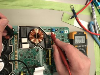
Alrighty, the resistors measured 9.7Ω, which I assume is correct (4.7Ω x 2 = 9.4Ω), so I assume that it good. Here is how I tested it.

JdW1Kyhm.jpg


Full image: https://i.imgur.com/JdW1Kyh.jpg

We are about to re-assemble the OBC, top up the coolant and run the coolant pump cycle, and see what happens.

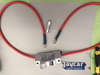
I am going to use a solar fuse (1000V 20A) for testing so that we do not have to wait 4 weeks for the OEM fuse if something goes awry.

Nov5FCAm.jpg


If all is good, I'll repot the doghouse and call it fixed.
 
And for the good news, it looks like ours is fixed, woot!

So, what did we do.

  • Replaced the two caps with new through the hole caps, however these were soldered to the pins with the two pins that were soldered onto the upriser board used for each leg of the caps (i.e. each leg had the two pins). It was tricky, but it helped by having something between the waffle plate and the PCB to prevent the pins dropping through while de-soldering the board and soldering the new board. The upriser needs to be cut into four pieces to be removed.
  • Checked the relay using a bench-top power supply set to 4.5V@500mA (though coulomb suggested that 200mA would be better, and I agree, lower amps, less likely to blow the diode if you get the polarity wrong). We were extra careful to triple check that we had the polarity correct.
  • Checked the resistors (2 x 4.7Ω) and they measured 9.7Ω, I assume they are in series and therefore 9.7Ω was expected.
  • Added thick cables to the solar fuse holder and crimped on some connectors, used a 1000V 20A PV fuse, this was done for testing so that we did not blow up the OEM fuse which takes 4 weeks to arrive.
  • Reassembled the OBC, re-installed in the car.
  • Turned on the car, and all error lights were gone. YAY!
  • Toped up the coolant, and set to purge the system using the non-MUT-III method (since we do not have a MUT-III).
  • Set the system to purge air for 15 mins, coolant level remained the same.
  • Plugged in the 10A charger that came with our outlander (a proper EVSE charger, not the dodgy cable that came with the car).
  • Contacts clicked, and she started to charge.
  • Left to charge for 30mins, checking it regularly, and bingo, we got an extra bar.

So, we are going to let it go for a bit longer and keep an eye on it, but I think it is fixed.

Next up we will install the OEM fuse tomorrow, and repot the doghouse with neutral cure silicone, reseal the top lid of the OBC with silicone, and we are done.

A big big thank you to @coulomb, @kiev and @skylogger for all your help.

Edit: Now have two bars more than when we started the charge. :)
Edit 2: Now three bars up, now at 3/4 charge.
 
This morning we have put in the OEM fuse, and put it back on charge. Once we are at 100% SOC, we are going to disconnect the HV and 12V, open the OBC and repot the doghouse with neutral cure silicone.
 
Great news Electronpusher
It is now looking like the majority of faults on these chargers are not major "power train" issues
I'm starting to think that either there is a power surge, or like KIEV says, a low 12v aux supply which puts the
chargers controller into a destructive state. If these were caused by power surge, then replacing the caps
and fuse are all that was required to get back running. If it was a 12v aux battery situation, It might be a
one off situation or the 12v battery may need to be replaced. There is a chicken or the egg situation, where if the 20 amp fuse
blows, the sudden load change may cause an inductive spike which feeds back and blows the 2x snubber caps.
There could also be the alternative theory that when the caps blow, they may first form a short, which can blow the fuse, but
then the short does not last long, as the caps end up becoming vaporised.
It's good to see that a few of these chargers are now getting fixed without any waffle semiconductor faults.
Seems that the waffle semiconductors are fairly robust.
 
Yes it is great, we are happy. Charged to 100% today and allowed to complete balancing. Then disconnected the 12V and drive battery, left it for a few hours and then filled the hole in the doghouse with neutral cure silicon. Now we have to wait 72 hours for it to fully cure, before I put the top back on the OBC with a fresh silicone seal, reconnect the 12V and drive battery and she is good to go.

Mitsubishi Cost $5000AUD ($4500 for the OBC and additional costs for labour ~$500).

My cost: ~$150 ($22AUD parts [$20AUD OEM Fuse, $2AUD snubber caps], and other things like coolant, heat transfer compound, solar fuse).

A nice little saving, and I learnt a lot too. A big FU to Mitsubishi.
 
Hello tout le monde,

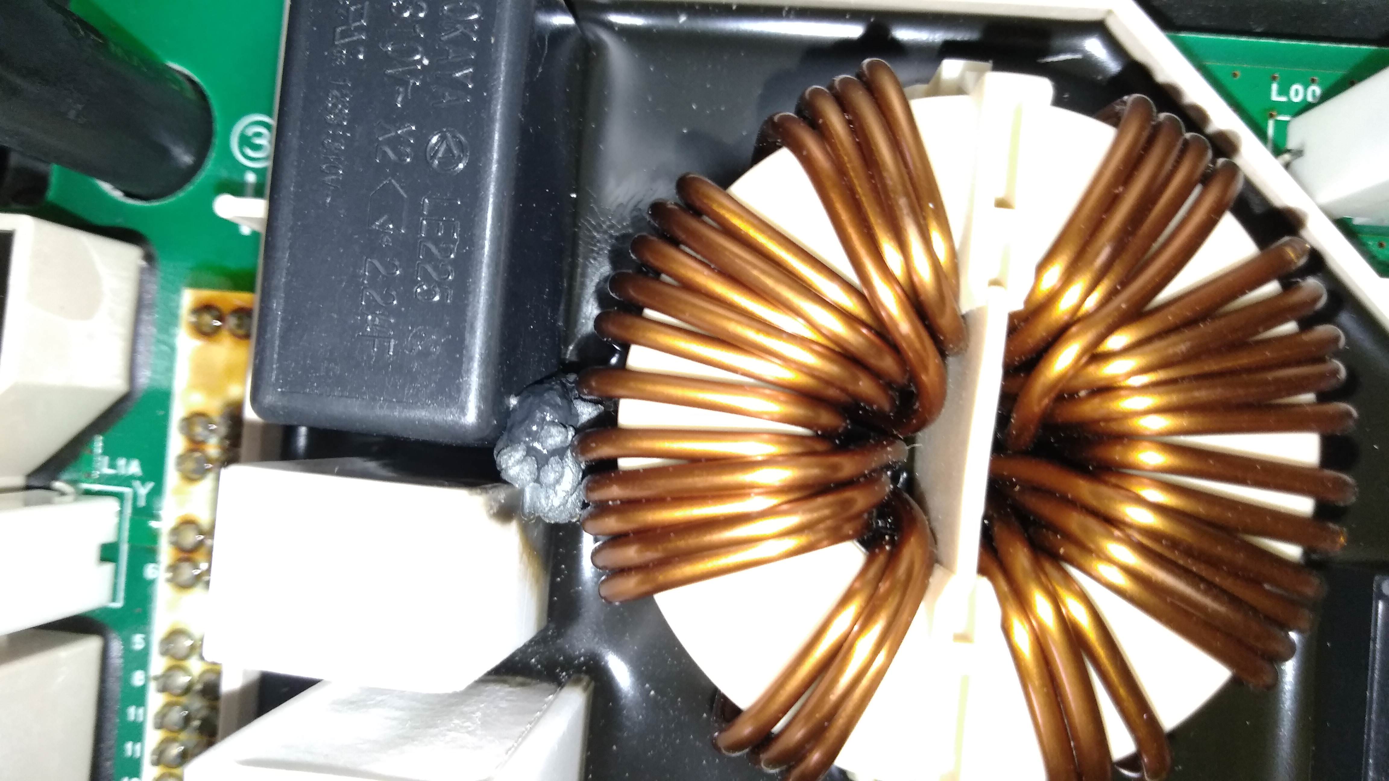
Today I made new photos. On this one we can see the fused resistor. I did not see last time. We also see that the rubbery potting has boiled.
KBIGGTD.jpg

Another problem, the 2x 2.2 microfarad capacitor seems inflated on both long sides.
Good news: the relay operates with a 4.5 volt battery, and I get 0 ohm when it is activated.
Questions:
1) should I change the capacitor as a precaution? I have not found a supplier in Europe for the Okaya capacitor, do you think that one is correct?
https://content.kemet.com/datasheets/KEM_F3001_F861_X2_310.pdf
Same nominal voltage, same characteristics and same dimensions.

2) The reference of the fused resistor is hidden by the resistor P10k. Is it a 5k or a 7k Tamura? what reference to change it?
3) If the P10K resistor is also fused, what reference to change it?
 
Great job! Now is that the same board that controls the charging rate? And if so, how can the charging rate be increased?

:idea:
 
ChristopheFR said:
.... On this one we can see the fused resistor. I did not see last time. We also see that the rubbery potting has boiled.
Questions:
1) should I change the capacitor as a precaution? I have not found a supplier in Europe for the Okaya capacitor, do you think that one is correct?
https://content.kemet.com/datasheets/KEM_F3001_F861_X2_310.pdf
Same nominal voltage, same characteristics and same dimensions.
2) The reference of the fused resistor is hidden by the resistor P10k. Is it a 5k or a 7k Tamura? what reference to change it?
3) If the P10K resistor is also fused, what reference to change it?

Good work to catch the resistor and the safety (X2) cap.
1. yes change it while you are in there, the kemet should be a good substitute.
2. and 3. It is a 7K without the internal fuse, not sure about substitutes for these parts.

The Tam datasheets are linked in this post: http://myimiev.com/forum/viewtopic.php?f=23&t=4079&start=140#p37274

Even though the relay seems okay by your test, it doesn't prove that it wasn't damaged--i would bet that it has been damaged and should also be replaced, especially since so many other parts have damage, you may as well replace the relay as cheap insurance. In addition you need to determine what caused the power resistors to get overheated--were the relay contacts frosted over and not making good contact, or did something interrupt the 5V supply to the relay coil?

You will need to desolder the waffle plate to get access for the cap and resistors, and the relay. Unless you are quite skilled at this sort of work, then i would recommend that you find an electronics repair shop with a powerful vacuum desoldering gun to help you make these repairs--it is difficult to desolder the plate without the right equipment.

Considering the amount of work to remove the plate is also why i recommend to replace the relay--once you are in there it is easy to replace, and you don't want to have to repeat all this because of an unknown failure of the relay.
 
ChristopheFR said:
Electronpusher : I forgot in my last message : félicitation pour cette excellente nouvelle! :p

Merci, j'espère que votre solution va bien.

Excuse my translation, I cannot speak French so used google.
 
ChristopheFR said:
We also see that the rubbery potting has boiled.
Actually, that grey stuff looks rather similar to some goo that oozed from a similar capacitor (also 2.2 μF across the line) in an Elcon/TC charger:

attachment.php


(From https://www.diyelectriccar.com/forums/showthread.php?p=1019597#post1019597, in case you are interested in all the details. )

With closer inspection, does it appear to have come from the capacitor? It might be the outer epoxy that's for fire extinguishing. It may have gotten too hot from the resistor that overheated.

1) should I change the capacitor as a precaution?
Given the above, and the difficulty of getting to these components, I'd say definitely yes.

I have not found a supplier in Europe for the Okaya capacitor, do you think that one is correct?
https://content.kemet.com/datasheets/KEM_F3001_F861_X2_310.pdf
I agree with Kiev, that replacement appears to be suitable, as long as the lead spacing of 27.5 mm is the same as the PCB hole spacing, as it very likely is (these parts are thankfully pretty standardized). However, the Kemet is rated for -40°C to +110°C, whereas the 310 V Okayas seem to be rated for -55°C to +110°C. If your vehicle is likely to see temperatures below -40°C when parked (it will get nice and warm after operating for a few minutes), then you might want to find a wider temperature range replacement.

The Okaya data seems very sparse compared to the Kemet's.

[ Edit: changed Okaya link to the LE-MX PDF file. I initially read LF. ]
 
ChristopheFR:

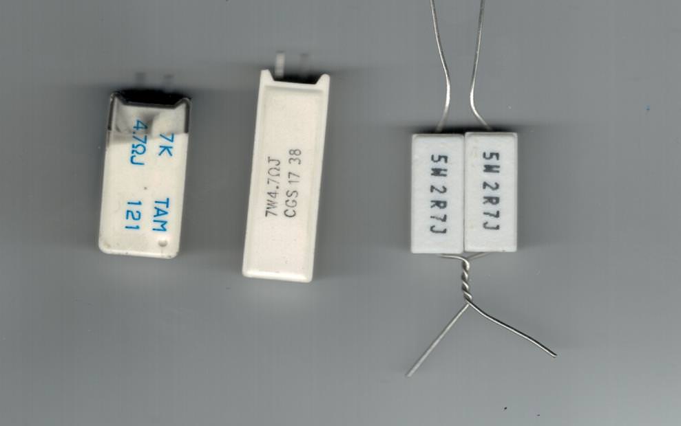
In this picture, the resistor on the left is the faulty resistor that I removed from the charger that I fixed.
It appears to have a 7 watt rating.
The resistor in the middle is a close equivalent that I found and purchased from DIGIKEY online and shipped from the USA.
The setup on the right is two 2.7 ohm resistors in series, which gives 5.4 ohms and they are rated at 5 watts but these are in series and are also in series with the other 4.7R Resistor in the doghouse. The leads could be formed like shown so it would still fit into the PCB.
I was looking at using this as an alternative until I found the Digikey option.

hzlgktA.jpg
 
I worry that while the TE Connectivity (guessed by the CGS marking) part is rated for 10 times nominal power for 5 seconds, a cheapo 5 W resistor is rated for only 5 times nominal power for 5 seconds. [ Edit: guessing the TE Connectivity SQ series. ]

This is in a part that will see 120 VAC (presuming 240 VAC at the input, after diode drops) for a fraction of one second. That's P = E²/R = 120²/4.7 = 3064 W! That's 438x its nominal power. Granted, that power pulse dies away quickly and exponentially, but I don't think you want to skimp on pre-charge resistor quality.

For any pre-charge application, I usually like to use the HS series of aluminium cased resistor, which can handle 25 times nominal power for a second, but they would be really awkward to mount. It looks like the originals will last just fine as long as nothing else fails, so I don't think we need to bolt one of those to the chassis. Though something to keep in mind if they do start to blow too frequently.
 
Thank you for your answers to all.

To repair my PCB, I'll ask a friend to do the work, he has an electronics lab at the university.

I just have to buy all the components, and to remove the rubbery potting.
Are there small components hidden under the rubbery potting?

The P10K resistor is composed of a resistor and a thermal fuse, and I have found no equivalent in Europe.

I found a resistor 5w and 4.7 ohm equivalent at Digi-key, but without thermal fuse.
Is there a fire hazard?
 
ChristophER:

4.7R at 5watts is a probably not good enough, as the original was a 7 watt rating. Try looking for the 7 watt or or 10 watt versions on
Digikey.

When you test the relay, you might want to try opening and closing it 20 or 30 times and see that it goes to zero ohms each time.
with micro pitting on the contacts , you might find that majority of times, the relay closes ok, and 1 or 2 times its intermittent.
If the relay does not close 100% then current will still flow through resistors for too long and cause them to burn out.

I ended up using the 7W resistor that I found on Digikey, which was the closest I could find to the original at the time.
If I work on another charger with this problem, or re-work this one, It probably would be better to improve on the original
part since this seems to be a weak point of the original design. I found several versions of 10 watt resistors on Digikey
some radial (two leads coming out of same end) and some axial. The Axial lead could be bent over and extended to
still fit the pcb layout. Most of the 10 watt resistors I found seemed to be smaller diameter and longer, and the length
became a problem as it would be too tall and probably bump into the controller PCB on top. I was also looking at
maybe using 2x 10 ohm 5 watt resistors in parallel which would be 5 ohms at 10 watts total, but lead forming was a problem.
COULOMB Brought up a good point that in the more detailed specs on the resistors, they give a wattage rating over a period of time.
So finding resistors with a higher peak wattage rating for a short period of time would be beneficial.
 
Hi Kiev , Coulomb:
I might get a chance to work on another IMIEV Charger. I got a call last week that another member of the AEVA (Australian EV Association) has a IMIEV that is causing problems when plugging into the Bollards at the University of WA to charge, and so far it has caused two of the Bollards (EVSE Charge stations) to fail. When the car is plugged into other public charging stations, it works ok, and no damage to the charging stations. The person that normally looks after the charging stations at the Uni is away sick at the moment, so I think the two charging stations are still down. The persion with this car, is having the OBC replaced to resolve the issue so they can continue using the Uni's charging stations in the future. The charger is being replaced by a EV servicing place in Perth, and I asked the owner of the car if I could have the bad charger once this is completed (around 4 weeks to get the new charger from Mitsubishi). The owner of the car wanted it done this way so as to have a waranty on the repairs.

My theory of what the problem is: If the relay contacts weld short and are always bypassing the 2x 4.7 ohm resistors, Then when the charger is first connected to the charging station, a big surge of current is presented to the charging station. Inside the charging station, a fuse, circuit breaker, or maybe some circuit damage has occurred due to the surge. The two Uni charging stations are only designed to handle a 20 amp max load. The other charging stations that the owner has plugged into have 32 amp max loads. I think the other public station that is being used happens to be robust enough to cope with the surge current from the damaged pre-charge circuit. The two Uni charging stations are not commercial units but were built by the Uni itself.
 
That's interesting. I had to replace the plug on our stock charging cord (2010 one with no EVSE) shortly before the charger failed as it was melting and falling apart. I wonder if issues with the charger might have contributed to that, or issues with the plug might have contributed to the charger issue - there was some arcing in the plug just before it was replaced.
 
Howdy skylogger,

At first i wouldn't think this possible, but then you noted that these were home-built evse units that failed--so we don't know what they are doing within with respect to the charging protocol, ground checks, communications, etc., and i think you have a good theory.

i hope you get to take a look at fixing that OBC and can confirm the suspect relay.
 
mikeduffy:
It sounds like you had the charger replaced under warranty, but are are still having issues at the dealership?
I sent you a PM, and I might have spare parts that could be used to trouble shoot EV-ECU issue.
Is it possible for you to get your hand on / keep the original broken charger? I would be interested in having a look at it
and using it for research if you can get your hands on it. (If dealership does not require keeping it under warranty conditions)
 
Back
Top