The Troubleshooting and Repair for On-board Charger (OBC) Thread

Mitsubishi i-MiEV Forum

Help Support Mitsubishi i-MiEV Forum:

This site may earn a commission from merchant affiliate links, including eBay, Amazon, and others.
I happened across this today, from the DiyElectricCar.com forum, DIY Tesla Controller topic:

"Root cause of the drive unit inverter failures discovered and fixed.
NOT caused by overcurrent through the igbts but rather the combination of using 8.8kHz switching frequency through a very low inductance stator and the sudden release of the main contactor on an overcurrent detection. The small drive unit inverter works perfectly at 17.6khz switching frequency and setting tripmode to prechon ensures the pre charge resistor can provide a path back to the battery during release of the main contactor. This was tested to the Nth degree on my recent trip to Romania :) "

Jack is talking about a motor controller here, but it's still a power conversion circuit. It looks like he's saying that as long as the pre-charge resistor exists across the main contactor, then there is a path back to the battery for the energy in the switching inductor (in this case, the stator of the induction motor).

  • In the case of the On Board Charrger, we have the pre-charge resistor across the relay all the time, so if the relay opens, there is still a path back to the battery. [ Edit: duh, it's back to the mains. This is probably not relevant. ]
  • Of course, if the pre-charge resistor has failed, then this is not the case.
  • If the fuse located in the motor controller opens for any reason, then there is no path back to the battery. So something inside the charrger has to "take the hit", and it looks like these capacitors are it. It might be worth installing much larger replacements, possibly with a high pulse power series resistor, which could absorb that energy. The Elcon/TC charrgers have several such RC networks, and I've wondered what their purpose is. They have often failed too, suggesting that they are also under-specified.
  • We know that the fuse blowing is a not uncommon event. Also not uncommon is for those blue capacitors, which are physically but not electrically near the pre-charge resistors and relay, to blow in spectacular fashion.
  • I think that the lesson is that if [ either of ] the fuse [ or the pre-charge resistors ] goes open circuit, then we can expect the capacitors to have to absorb the energy of the inductors, and it seems that they are not large enough to cope with this amount of energy. [ Edit: and of course, capacitors are not normally dissipative elements. Hence the suggestion of a high pulse-power resistor in series. ]
  • It's unclear to me at this point whether suddenly taking away the AC input is a similar event; I'll ponder more.
  • Suddenly losing altogether or having weak 12 VDC power to the charrger may trigger a similar event. It's just not known whether the processor has the ability to detect low 12 V power, or the 5 or 3.3 V that the processor works from. Perhaps it does and shuts down the charge current cleanly, but the manufacturer quite possibly didn't bother.
  • It remains my belief that they pre-charge resistors in the charrger are a little weak for the peak load that they are expected to withstand every time the power to the charrger is turned on. We've seen several but by no means all pre-charge resistors burned, and I don't think we can establish cause and effect as yet. [ Edit: as per the first point, this seems irrelevant to the sudden interruption theory. ]

[ Edit: incorrect smiley strength in quotation :D ]
 
hello - am I understanding this correctly that these cap and resistor are there to protect the relay contact, mainly upon disconnect ? if so, would it more prudent to turn off charging externally by turning off the EVSE AC power rather relying on the relay contact ? am just looking for some preemptive action to protect the inverter/charger. Then what's up trying to keep the inverter/charger cool ?

thanks
 
Phximiev said:
Great job! Now is that the same board that controls the charging rate? And if so, how can the charging rate be increased?

:idea:

Just a follow-up and out of curiosity, but has anyone thought about this question in terms of modifying or repairing the board?
 
pbui19 said:
am I understanding this correctly that these cap and resistor are there to protect the relay contact, mainly upon disconnect ?
No. The relay merely shorts the pre-charge resistors, so that full power is available for charging. Certainly, it's best to stop charging by the switch on the J1772 connector. My theory is that the problem is due to some abnormal stopping of charging, and we don't know the reason(s) for this(these) as yet.

But as I try to explain this, I realise I'm very rusty on the fundamentals, and need to think about this a bit more. Sorry if I've caused confusion.
 
Hello tout le monde

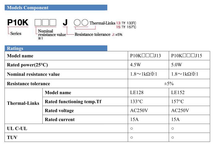
I have a question about the resistor P10K

Here is the technical sheet: https://imgur.com/6vaxWtx

first page is 10 watts:
second page is 5 watts
5hkZnxs.jpg

dnf9ZXP.jpg


Is the power 5 Watt or 10 Watt?

I found a resistor 7 watt, and its height is 39 mm, so I just have raise the first pcb 5 mm and it's ok.
https://imgur.com/MUjXuPC

What do you think? I replace both resistors 4R7 by two resistors 7 watt?
 
coulomb said:
pbui19 said:
am I understanding this correctly that these cap and resistor are there to protect the relay contact, mainly upon disconnect ?
No. The relay merely shorts the pre-charge resistors, so that full power is available for charging. Certainly, it's best to stop charging by the switch on the J1772 connector. My theory is that the problem is due to some abnormal stopping of charging, and we don't know the reason(s) for this(these) as yet.
Not all J1772 plugs have switches fitted to the trigger, it's an optional part of the spec. My Rolec charger charger for example does not have a switch on the trigger, and I don't think the OEM granny charger does either.

So unplugging this type of charger relies on the pilot signal breaking before the Phase and Neutral.
 
DBMandrake said:
Not all J1772 plugs have switches fitted to the trigger, it's an optional part of the spec...
Interesting, as in North America I've never seen a J1772 plug without a disconnect switch. Checking out Wikipedia, the schematic shows a switch in the handle. https://en.wikipedia.org/wiki/SAE_J1772 Perhaps an older version of J1772 allowed that?

Worried about the abrupt current interruption using my 240vac mechanical timer, I was actually looking at this schematic with the idea of opening up the handle and have my mechanical charging timer simply replace the handle switch in order to gracefully cut off power to the car... :roll: :geek:
 
ChristophER:
Interesting find on the data sheet for the resistor. I read this a couple of times, and it sounds like they take the "pellet" of a 10 watt rated resistor and add the thermal link, and the addition of the link causes the overall rating of the device to be de-rated to down to 5 watts.
It is interesting that based on this, it looks like between the two resistors, they are putting a 5 watt (with thermal link) in series with a 7 watt.
I'm thinking at the end of the day, it's going to come down to picking what resistors you can actually get your hands on. using 2x 7 watt resistors would be better than the original 5 watt and 7 watt combination in one way, but does the version you found have a thermal link? I guess when you look at the case I had, The 7 watt resistor that did not have the thermal link was the one that blew open, so the thermal link did not actually protect that one.

JoeS: using the timer in the circuit of the gun trigger sounds like a good idea. That would definately allow the charger to go through its natural shut down proceedure in a safe way before the mains voltage is disconnected.

DBMandrake:
On all the 2010 IMIEVs here in Australia with the original charger cord (no EVSE), The connector "Guns" have the trigger that connects the proximity pin to ground when the trigger is released. All of the EVSE and charging stations I've come across here in Australia also have the Trigger/latch. I once came across trying to use a LEAF EVSE on my IMIEV, and thought I had a faulty EVSE, but when I jiggled the gun it started working. I found the trigger assembly had a latch across the top of the connector that was a tiny bit wide and did not smoothly easily drop into the grove on the car connector. This was keeping the trigger from fully releasing and making the ground connection to the proximity pin. I filed down the plastic on the latch and coud then use the EVSE without issue.
 
skylogger said:
DBMandrake:
On all the 2010 IMIEVs here in Australia with the original charger cord (no EVSE), The connector "Guns" have the trigger that connects the proximity pin to ground when the trigger is released. All of the EVSE and charging stations I've come across here in Australia also have the Trigger/latch. I once came across trying to use a LEAF EVSE on my IMIEV, and thought I had a faulty EVSE, but when I jiggled the gun it started working. I found the trigger assembly had a latch across the top of the connector that was a tiny bit wide and did not smoothly easily drop into the grove on the car connector. This was keeping the trigger from fully releasing and making the ground connection to the proximity pin. I filed down the plastic on the latch and coud then use the EVSE without issue.
They all have the trigger as it is also part of the mechanical latch that holds the plug in.

But try pressing the trigger while the car is charging to see if it stops the charging - with my Rolec charger it definitely continues to charge while the trigger is pressed and does not stop until the plug is physically removed.

I'd have to test it again to be 100% sure, but I think my OEM Yazaki charger that came with the car is the same.

Circuit diagrams typically show the trigger as having a switch connected but I don't think it was ever a mandatory part of the spec, and the pilot line uses a shorter pin that is designed to disconnect first when the plug is withdrawn, this causes the charging to stop cleanly before the AC lines are disconnected to prevent arcing etc.
 
It has been asked before, what would be an adequate resin to replace the original one in the doghouse.
After discussing this with a 3M representative, the suggested product is the following:
3M Scotchcast 2131 Electrical Insulating Resin

Around 47 EUR for 173ml (55 USD for about 6oz)

This is what I'm intending to use.
 
footswitch:
The potting in the "doghouse" is a rubbery type substance, while the potting on the waffle board is a hard solid resin type potting.
If you are replacing the potting around the resistors, caps, and relay in the doghouse, I would still stick with a rubbery type, rather than
the hard resin type. Particularly because since we currently still do not know what the exact cause of these parts burning out, there may
be a requirement to re-work them again in the hopefully far away future. It's a lot easier to dig out the rubbery potting than to try and remove the solid resin type potting. Coulomb has suggested using a natural cure silicone sealant "silastic". I also agree that a silicone sealant would work, but make sure its the "natural cure" as the other types use an acid for curing which can cause corrosion and oxidation.
I've seen this used in HV circuits previously with no problems. It acts as a vibration buffer, and provides a barrier to dust and humidity.
If you are re-working the waffle on the bottom, There may be a benefit of using a resin that provides some heat dissipation,
but not 100% sure on that, as the semiconductors probably get enough of this already from being attached to the heatsink.
 
skylogger said:
Coulomb has suggested using a natural cure silicone sealant "silastic".
That's neutral cure, as in neutral pH. The kind that cures with acetic acid is of course acidic, which in addition to the corrosion etc is conductive, at least while curing (which could take days to complete if it's a thick application, which this is). You don't want it conducting :) . It doesn't need to be Silastic brand; our local hardware store has a cheap brand that seems perfectly adequate. It's AU$6.20 (under 4€) in a 300 g tube, which is way more than you'll need. You'll also need a $2 caulking gun in the unlikely event that you don't already have one.
 
DBMandrake said:
But try pressing the trigger while the car is charging to see if it stops the charging - with my Rolec charger it definitely continues to charge while the trigger is pressed and does not stop until the plug is physically removed.

I'd have to test it again to be 100% sure, but I think my OEM Yazaki charger that came with the car is the same.
All of my EVSEs stop charging when the trigger is pressed, including my EVSEupgraded OEM cord. I had to pay attention to this detail when picking out a lock for the cord. Most locks I tried didn't fit snugly enough and would allow someone to stop the car from charging by pushing the trigger.

Regarding cutting the power off external to the car, I've been doing that every winter since I got the car. Since the meter is inside, I try to stop it just as it clicks over, and the most accurate way to do that is to flip the switch feeding the outlet (EVSE hangs inside the garage, car parked outside). Good thing the i-MiEV won't be driven much in the winter now.
 
PV1 said:
DBMandrake said:
But try pressing the trigger while the car is charging to see if it stops the charging - with my Rolec charger it definitely continues to charge while the trigger is pressed and does not stop until the plug is physically removed.

I'd have to test it again to be 100% sure, but I think my OEM Yazaki charger that came with the car is the same.
All of my EVSEs stop charging when the trigger is pressed, including my EVSEupgraded OEM cord. I had to pay attention to this detail when picking out a lock for the cord. Most locks I tried didn't fit snugly enough and would allow someone to stop the car from charging by pushing the trigger.
You're right. I checked a bit more closely and squeezing the trigger does indeed stop the car charging. :oops: The thing that was fooling me is that the green charge light remains on the EVSE, the EVSE contactor remains closed, and the charge light and fuel gauge all stay lit on the dashboard of the car.

However when I check the power consumption of the house I can see that the car pauses charging while the trigger is pressed and resumes when it is released.
 
That's where the difference is then. My Eaton EVSE drops the contactor out when the button is pressed. Either way, current flow stops, which is the important part.
 
PV1 said:
That's where the difference is then. My Eaton EVSE drops the contactor out when the button is pressed. Either way, current flow stops, which is the important part.
Yes. The car stops drawing power, but the EVSE contactor remains engaged and humming away, and the charge gauge remains lit on the dashboard.

Not sure if it's related, but with my Rolec wall charger if the car is plugged in but fully charged the EVSE contactors will drop out and the light go to blue (not charging) as you would expect, but turning the key on in the car will cause the contactor in the EVSE to close and the light to change to the green charging mode! Even though the car is not capable of charging with the key on.

Yet the portable OEM EVSE that came with the car does not engage if the key is turned on while connected... There must be a bit of latitude in the spec ?
 
Where are the control and proximity wires connected on the OBC? I tried to crawl through the posts but couldn't find any info.
 
Hi Target:
There are two connectors coming out of the OBC Towards the rear bumper.
One connector has the Active, Neutral, and Ground lines from the charging port conntector.
The other connector is called E-03 and has all the signal and supply lines from all over the car
going into the charger. In you look at page 9 of this thread, you wil see a pinout that I drew
up for E-03 and CN101 connectors. (E-03 is the external connector and CN101 is the internal connector)
Pins 9 and 5 are the ones you are interested in.
Pin 9 is the proximity pin signal.
I think In the early 2010 model, the control pin was not supported so there is no wire from the
charging port to the charger. On mid year 2010 and later I-MIEV i think the control signal goes to pin 5.
There was also mods where a resistor and diode were placed across the pin and ground of the charing port connector
so it would dummy out a signal back to the EVSE to make the I-MIEV look compliant so a EVSE or charging
station would work.
 
hi y'all - I am still struggling to convince myself that it's best to stop charge with the trigger. Most relay contact needs some sort of protection upon a disconnect, due to the inductance back discharge. Recall the old days with ignition points & condensers. Sure, you would think that Mitsu designed it so that the trigger disconnects gracefully. But from the limited reversed engineering schematic we manage to come up with so far, it seems that the trigger simply & abruptly switch off the relay, thus taxing the bypass (now heated from operation) resistors & caps.

Joes has been abruptly turning off charging with his external timer for quite a while. Do we know the statistic how the charging dis-connect of the "failed" inverter/charger ?

If in fact the trigger is simply turning off a relay, then turning-off externally would move that contact arcing outside the vehicle, where it can be mitigated, with thrysistor or suppressor etc...

A simple double-pole 240vac 20A switch costs $10, way more palatable than the inverter/charger.
 
Back
Top