The Troubleshooting and Repair for On-board Charger (OBC) Thread

Mitsubishi i-MiEV Forum

Help Support Mitsubishi i-MiEV Forum:

This site may earn a commission from merchant affiliate links, including eBay, Amazon, and others.
ctromley said:
That bulging capacitor seems to be identical to C106, the 2.2 μF cap next to the 4.7 Ω ceramic resistors on the bottom board.
Beware! In one I dealt with recently, it was a 1 μF part with different spacing. But this mains filter was internal, not in a separate box on top, so it may be different.

My question is, why is this happening? On the bottom board it would be reasonable to assume the cap is not an issue itself, it only failed because it was next to a ceramic resistor that ran too hot and too long. I don't see that happening for the one in the external doghouse.

Too much heat both cases? Is there any real heat to speak of being generated in the external doghouse, or is it just because it's on top of the too-hot OBC?
I would love to know. My guess is heat. Possibly caused by the relay failing (either pitted contacts, these tiny relays run at very close to 100% of rated current most of the time), or due to a lack of coil drive, possibly due to failing connecting ribbon. That would put some kilowatts of power through the pre-charge resistors until the fuse blew. I have no idea how long it takes for the thermal fuse to let go; it seems unlikely that this would be long enough to affect the dog house on top of the inverter case, even with the case at 60-80°C already.

I note that the Leaf version of these OBCs sensibly uses regular wires and connectors that you can see and solder instead of that evil flexible ribbon. It just seems like the wrong thing to use in an automotive application. Or at least use less fine tracks; surely they could have gotten it down to about 20 connections at about 3 mm spacing.

So... dunno.
 
coulomb said:
ctromley said:
As for the fuse, does this look good? https://www.tme.com/us/en-us/details/bf157x/thermal-fuses/aupo/ ... This is a 157 °C version that matches the original.
Great find! I have used the 10 A version of these. The problem is, the surge current is over 25 A RMS, and I can't find the surge rating for these fuses. The 16 A version should be better than the 10 A ones I had in stock. If you can find 20 A or higher, that would be even better again.

Hmmm. I may be veering into hillbilly country here (and crowding the little real estate there is to deal with), but how about functionally replacing the P10K resistor with your pair of paralleled 10 Ω Ohmite resistors in series with a parallel pair of the AuPo 16 A thermal fuses I found? If this is a thermal fuse meant to release at a set temp, the two paralleled 16 A fuses only ensure they will carry the current they need, and they'll still release at 157 °C. If one releases first, the extra load on the other should pop it soon thereafter.

Wouldn't that work?
 
ctromley said:
how about functionally replacing the P10K resistor with your pair of paralleled 10 Ω Ohmite resistors in series with a parallel pair of the AuPo 16 A thermal fuses I found?
Wouldn't that work?
Yes, I think that's a good idea. I wish I'd thought of it with my paltry 10 A parts.

Now to find a source of ceramic cement that is safe for mains voltage.
 
The thermal fuse is likely a good safety item, but in household appliances i have found them to fail and be a nuisance--making the device useless for no apparent reason. Almost every failed device having a heating element on which i have done troubleshooting, the culprit was a blown thermal fuse.
They are cheaply-made cheesy fuses with a spring-loaded wax pellet actuator--a low-cost solution but not robust or reliable from what i have seen.

In the OBC there have been a few failures reported, but it seems to not be a primary culprit.

At least when you roll your own resistor-fuse package it will be easily accessible when the fuse blows again.
 
ctromley said:
The component marked SA (spark arrestor?) has no conductivity in either direction. A close look reveals what looks like a fracture around the glass tube near the right lead

It's a gas discharge tube lightning surge arrestor, and if the glass is cracked then the gas has escaped and will no longer function.

From Bournes websticle:
GDT surge arrestor devices are designed to operate on the gas-physical principle of the highly effective arc discharge. Essentially a voltage dependent switch, the GDT maintains a high impedance off-state until a voltage exceeds the device’s sparkover voltage. At this point, the gas in the GDT becomes fully ionized and conduction takes place within a fraction of microsecond.
During arc-over, the GDT exhibits the low impedance of a crowbar device resulting in very low on-state voltage (arc voltage). The crowbar effect of the GDT effectively limits the overvoltage to a low level and shunts the associated follow current away from downstream components and circuitry. When the surge event subsides and the system voltage returns to normal levels, the GDT will reset into its high impedance (off) state.
 
coulomb said:
Yes, I think that's a good idea. I wish I'd thought of it with my paltry 10 A parts.

Now to find a source of ceramic cement that is safe for mains voltage.

Proving yet again that sometimes even a blind squirrel can find a nut. Speaking of which, I just got my desolder station, which makes a bid deal about handling lead-free solder well. Which got this noob wondering, should I be using lead free solder?

I've read that desoldering sometimes goes better by adding a little leaded solder before desoldering, but when I install components should that be done with lead-free? I've never used the stuff.

Regarding thermal bonding, I was going to use silicone and keep the fuses and resistors close to each other, preferably in contact. (Isn't the P10K resistor just a wirewound resistor in series with a fuse, component bodies not touching, in a ceramic box filled with silicone?) While looking at neutral cure silicone I found that some of what's out there isn't recommended for temps over 100 °C. Silicone should be good enough for several times that temp. Doesn't seem right to use it on a 157 °C thermal fuse. I'm inclined to get the good stuff.
 
I think that temperature sensitive fuse is actually redundant as the resistors themselves do the job quite as well. I burnt several resistors (including the original ones) not knowing that I had a short circuit somewhere in the Waffle Plates AC input - it’s a painless act, doesn’t even smell of anything as the wound wire is well housed in ceramics. In the original resistor/fuse combination (which survived several blown partner resistors), when it finally had blown, the fuse was still intact. So I wouldn’t worry to much about replacing the fuse.
 
kiev said:
ctromley said:
The component marked SA (spark arrestor?) has no conductivity in either direction. A close look reveals what looks like a fracture around the glass tube near the right lead

It's a gas discharge tube lightning surge arrestor, and if the glass is cracked then the gas has escaped and will no longer function.

From Bournes websticle:
GDT surge arrestor devices are designed to operate on the gas-physical principle of the highly effective arc discharge. Essentially a voltage dependent switch, the GDT maintains a high impedance off-state until a voltage exceeds the device’s sparkover voltage. At this point, the gas in the GDT becomes fully ionized and conduction takes place within a fraction of microsecond.
During arc-over, the GDT exhibits the low impedance of a crowbar device resulting in very low on-state voltage (arc voltage). The crowbar effect of the GDT effectively limits the overvoltage to a low level and shunts the associated follow current away from downstream components and circuitry. When the surge event subsides and the system voltage returns to normal levels, the GDT will reset into its high impedance (off) state.

Interesting. Thanks for that. Makes sense, this thing goes between AC in and chassis ground. Looks like I have more parts searching to do.
 
ctromley said:
Looks like I have more parts searching to do.

Follow-up:

I haven't spent a lot of time searching yet, but it looks like I'm going nowhere fast. The i-MiEV gas discharge tube is a glass tube, roughly Ø5.5 x 9.5 mm, with axial leads and 15 mm lead spacing. Searching on the numbers found on the device gets me nothing. Everything in that category available now is what looks like a ceramic (or metal?) cylinder with metal end caps.

So what would the electrical gurus here use to protect a vehicle charrger from a lightning surge on the AC mains? These devices have DC voltage and current ratings. Voltage rating near but comfortably above mains voltage? Peak or RMS? What kind of current level is used for lightning protection? Anyone seen something of this sort in other EV charrgers? What was used there?

Specifying something like this is way beyond my understanding, but I'm even less comfortable not replacing what's in there now. Even a rule-of-thumb guess is better than nothing.
 
Found one on digikey that may be the same item
https://www.digikey.com/en/products/detail/mitsubishi-materials-u-s-a-corporation/DE37-362M-S00B/12144118?s=N4IgjCBcoKwOwE4qgMZQGYEMA2BnApgDQgD2UA2iAMwBsADHQAQBqIAusQA4AuUIAqgDsAltwDy6ALL5MuAK4AnfCAC%2BxALQRoINJCx4ipCiABMJmEjYrrQA
 
kiev said:
Found one on digikey that may be the same item
https://www.digikey.com/en/products/detail/mitsubishi-materials-u-s-a-corporation/DE37-362M-S00B/12144118?s=N4IgjCBcoKwOwE4qgMZQGYEMA2BnApgDQgD2UA2iAMwBsADHQAQBqIAusQA4AuUIAqgDsAltwDy6ALL5MuAK4AnfCAC%2BxALQRoINJCx4ipCiABMJmEjYrrQA

Oh thank you so much! I thought I was going to have go back to school to figure out what to put in there.

Mind you, your find is not the original part. (The original, also from Mitsubishi's electronics division, is bigger.) But the "362M" on your Digikey part matches part of the number on the original. I finally found a data sheet for it elsewhere, and "362M" means 3600 VDC sparkover voltage, ±20% (Littlefuse seems to use the same nomenclature.) But that part you found has a surge current rating of only 1500 A. Sounds like a lot, but apparently it's low for this kind of application. (And to make this even more confusing, the surge current rating is inconsistently listed - it might mean for 1 hit, 10 hits or more.)

Trying to get some background I stumbled on this: https://citel.us/en/gas-tube-surge-arrestors-for-90-240vac-type-a-pluggable-equipment . It describes how to use three MOVs and a GDT to protect the input of a 90-240 VAC universal input power supply. It ends up recommending a GDT with 3500 VDC sparkover and 10 kA surge current.

1) There are plenty of available GDTs from Bourns, Littlefuse, TDK, etc. that would fit. Am I basically free to choose any of them? For example this one? https://www.digikey.com/en/products/detail/bourns-inc/SA2-3600-CLT-STD/3915355

2) As for the MOVs, do their specs have any bearing on what GDT to use? The originals in my charrger are Panasonic ZNR V20471U, which seems to have been replaced by ERZV20D471, shown here: https://www.digikey.com/en/products...31?s=N4IgTCBcDaIKYCcBeBaAbmADAEwCwHYBGEAXQF8g .

3) The MOVs in my charrger have no visible damage, in fact they look brand new. If in fact this failure was caused by a surge, should the MOVs be replaced too? Is there any way to test them?
 
i think you would be ok to use most any GDT such as the one you found.

Not sure that anyone has reported a failed SA, but there have been some blown ZNRs, either here or on the Laef forum (laef OBC is about 90% common parts and design with Mits).
 
So it's been over a month now since I pulled the safety plug and disconnected the 12 V battery and started in on fixing my charrger. (Too many projects at once.) And I now remember this:

http://mmc-manuals.ru/manuals/i-miev/online/Service_Manual/2012/54/html/M154100230004500ENG.HTM

There's a caution at the top of that page warning against letting the car sit with the 12 V disconnected for "approximately 1 month or more." Apparently the BMU will lose track of the "battery learning value." If you click the blue arrow on that page it goes to another page that describes resetting the value. It requires a MUT III. I'm betting the car won't go to Ready if the learning value is lost, which means I'll need to get a tow to a dealer. Hoping to avoid that.

Can I just connect the 12 V battery again with the safety plug disconnected? (I suspect the issue is that there's a button battery somewhere that maintains the learning value, and it goes flat without the 12 V battery to keep it charged.) Or will connecting just the 12 V with the safety plug out throw some problematic codes? If so, I can put the safety plug back in too (after properly insulating any loose orange wire terminals first), or will that just throw a different set of codes if the charrger boards are still out? (Still waiting for the thermal fuses discussed earlier, which come from Poland.)

Also, I used these 1000 pF snubber caps to replace the lightly toasted ones in my charrger: https://www.digikey.com/en/products...aICwHYAcBaAhgJwMwAYAWAxgIw5gDWcGKAdgCYgC6AvkA They're the right value ±10%, rated at 3 kV, X7R and -55 ~ 125 °C for automotive applications, and cost $5.00 each. But they're tiny, like half the size of the original blue M&Ms. Does that make sense?
 
You should disconnect the 12V first [First off, last on], before doing any work on the HV pack, including d/c of the service plug.

Otherwise it will throw a code that may require a MUT to reset, but you might get lucky with cycling the negative terminal a few times.

i prefer the large round disk snubber caps in as high a voltage as you can find; those might work for awhile but they sure don't look very beefy for absorbing HV switching transients.
 
X7R are the worst type of ceramic capacitor you can readily get. Very compact, so ideal when space is limited and you don't care about other factors, but here space is not a big issue. I try to avoid them where possible.

Their capacitance varies wildly with temperature and even applied voltage, they can barely be called a capacitor.
 
As it happens, I'm having a devil of a time finding proper snubber caps. Anything higher than 3 kV rating is pretty darn rare.

Does anyone have a link to a candidate that I've apparently missed? (I think my noob status is keeping me from the good stuff the gurus have access to.)

If not, several years ago @kiev posted this: https://myimiev.com/forum/viewtopic.php?p=37542#p37542

I'll drop him a PM to find out if there are any left....
 
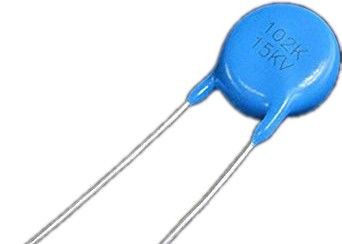
i'm seeing lots of them at this link, some at 15kV, 20kV and even 30kV; maybe they aren't available?
link: https://duckduckgo.com/?q=HV+disk+capacitors+1000pF&t=osx&iar=images&iax=images&ia=images

pc21217790-murata_electronics_dhr4e4c102k2fb_ceramic_disk_capacitor_high_voltage_1000pf_10_dc15k_volt.jpg
 
Howdy Vik,
That is very interesting to see, thank you for sharing the picture.
It appears to have identical circuits other than missing the C122 C121 snubber caps and the fenced area filled with flexible black potting.
The nichicon number on your board is likely newer than mine, PA4080RP130 vs PA4080RP100, but i haven't figured out a date code.

Was this board repaired or reworked--the solder joints to the waffle plate look very clean and clear-coated--not like any that i have ever seen (dirty joints with flux residue).
In what vehicle or application was this board used?
 
kiev said:
Was this board repaired or reworked--the solder joints to the waffle plate look very clean and clear-coated--not like any that i have ever seen (dirty joints with flux residue).
In what vehicle or application was this board used?
The board as new, no one was there.
Its called "leaf to home",
https://global.nissannews.com/en/releases/120530-01-e
 
Back
Top