The Troubleshooting and Repair for On-board Charger (OBC) Thread

Mitsubishi i-MiEV Forum

Help Support Mitsubishi i-MiEV Forum:

This site may earn a commission from merchant affiliate links, including eBay, Amazon, and others.
kiev said:
You should give thanks to Jay for the failed OBC used for all of these circuit tracings.
Good luck to you, hope the repair goes well.

Hey, thank you Kenny, I didn't know to what extent my original OBC had contributed to this effort. Glad to see this, though I managed to get factory replacements with the doghouse-free design on both my daily drivers, I've come across another couple of originals since, sent them on to other drivers, and may yet need to do this repair someday!
-Jay
 
siggs said:
Now 4.7 ohm resistor broken again (but looks like new)...
Bad solder joint.
If it wasn't for the bad solder joint, I would wonder if the usually mentioned TE Connectivity 4.7Ω 7 W ceramic resistor is up to high pulse loads. Each resistor gets about 120 VAC at peak, so that's P = V²/R = 120 × 120 / 4.7 = 3 kW, or some 429 times the nominal power rating of the resistor. It seems that the TAM resistors are specially made to withstand high peak pulse power; the datasheet says that with 2000μF (actual is 2040 μF ±20%) to charge, they can take up to about 250 VAC each. But maybe it's just marketing hype and all ceramic resistors can take this pulse power. I'm having a really hard time finding anything in stock that is rated for the required 60 joules of energy; the closest I can find is two 10Ω ceramic composition resistors in parallel (they are rated at 80 joules each, single pulse). It's a lot more expensive (US$2.38 x 2 versus US$0.78) but I don't have to raise the hight of the upper board, and I have the peace of mind that the part is rated for the tough job it needs to do.

But well done finding the bad solder joint. I wonder how many have this problem. I have a few 2012 OBCs to repair soon; I'll keep this in mind.

Edit: Mouser happen to have the 10Ω Ohmite ceramic composition resistor at a considerably lower price at present: US$1.86 each. Other values are much closer to Digi-key's price.
 
Hello, everyone

Click, click he's loading !! .. and the sun comes out.

Here is an excerpt from my photo documentation.
Looks terrible but is effective.
https://ibb.co/xgd5yLh
https://ibb.co/LQzmkzs
https://ibb.co/RyShgXJ

With sunny greetings from Germany
siggs
Slava Ukraini
 
Charging is good news!

Was the relay defective--it looks like one of the contacts has a frosty surface?

Stripping-Relay.jpg
 
Hello kiev
Unfortunately, I didn't pay special attention to it and I don't have it anymore.
But at first glance, they seemed like new. The photo is deceptive.

With sunny greetings from Germany
siggs
Slava Ukraini
 
Hi everyone and thanks to the main contributors of this thread for this incredible peace of reverse engineering.

Sorry to bother you with another case of a failed OBC - mine keeps blowing the resistors without any other symptoms.

After digging through all 103 pages I may have found a clue in the Waffle Plate. First I thought all the diode drops check out ok but just now I found something strange:

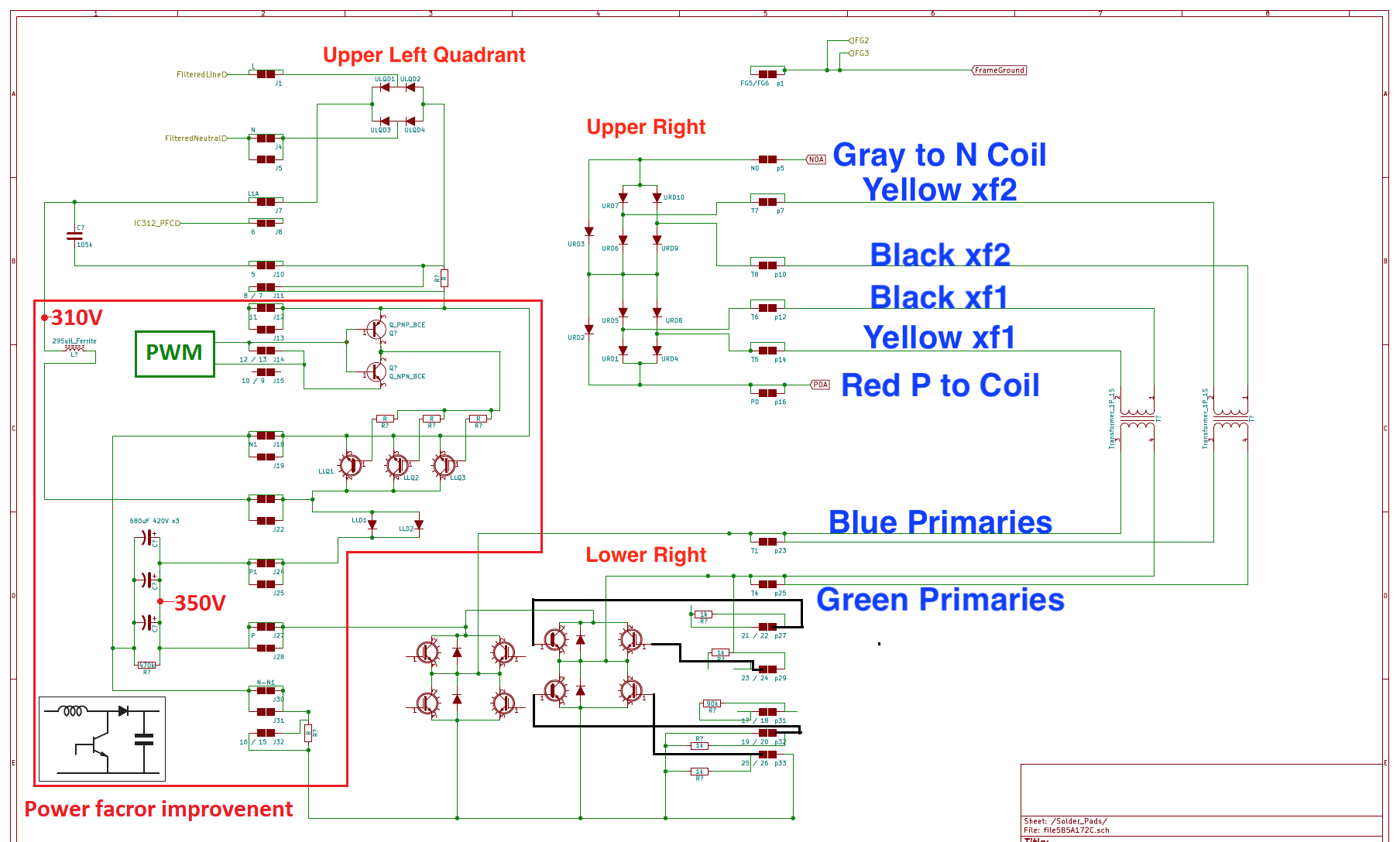
In the boost switching area (lower right) I measure .42V from T1 to P and from T4 to P as well as from 15/16 to T1 and 15/16to T4. So all the diodes seem to be ok.

After reading one of coulombs latest posts I checked from 15/16 to P - according to the circuit diagram there should be a double drop through the diodes I just measured separately here. But my Waffle Plate first shows a fluctuating, even negative voltage drop before finally stabilising @ .36V after 1 or 2 seconds. That somehow doesn’t look right. The plate ist still connected to the circuit board. A clue anyone what this is all about? May I assume my Waffle Plate is toast?

Greetings from across that big pond - Joerg
 
Your waffle plate is likely okay if all the other diode drops were good.

when the WP is still soldered in place there are other circuits on the power board that can affect the readings, such as the 16/15 solder joints. If you look on the schematic there is a 470k Ohms resistor between P and 16/15, in addition to the big capacitor bank. That bank was being charged up by you meter probes and caused the delayed reaction time that you observed.

06NxHJP.png
 
Phew, thanks Kenny for pointing that out. All the other diode drops are good, so I’m hoping my waffle plate is ok.

I’ll try to keep it short:
I have a 2012 C-Zero that won’t charge but goes to ´Ready´ and drives normally. When I plug in the J1772, the EVSE connects it’s relay, the car relays click, the ECU/ BMU goes through the test cycle with fan and coolant pump, the resistors blow, the dash warning light illuminates shortly and then everything switches off. So here is what I established so far:

The 12V aux is fully charged and passes the FSM testing procedure down to the 130Amp load test, which I don’t have the equipment for.
The OBD throws three active CAN bus messages: U1111, U1113 and U1116. They don’t seem related to the problem as the charrger gets the start command from the ECU.
The DC/DC along with the MCU fuse is fine.
I never had blown snubber caps or any other damage on the board except the precharge resistors.
I tested the relay in the precharge circuit, it shows 0 Ohms when activated and reliably switches a 10 Amp lightbulb load without problems, so the relay itself seems ok.
I verified the capacitor voltages on the control board and their transfer to the lower board. The ribbon cable checks out fine as well.
I tried a different control board - no luck, same problem.
I tried 17W ceramic resistors, also blew.
Somehow the precharge relay doesn’t seem to get activated in time before the resistors overheat. So I checked the connection from T301 to the relay as well as the 5V supply to it - no findings.
I’m a little bit at my wit’s end now and don’t really know where to go from here. Maybe the AC sensing circuit around IC501 on the lower board?
 
If the relay does not get energized then the ceramic resistors will blow because they are carrying more current than intended;
they can only carry the AC for a very short time, enough such that the voltage can be sensed and reported back to the controller, which can then pull the return side to ground to drive the relay coil.

Diodes D311,312,313, and 314 are used as a bridge rectifier to convert the AC to DC, where it gets divided down thru resistors and sent across a photocoupler (aka Opto-Isolator), PC305, and thru the ribbon cable to the upper control board.

So there are multiple possible failure points for this critical function:
Presence of AC? check that off since it is blowing the resistors
Sensing of the AC?
Low voltage supplies? 5V used to drive the relay created on the upper control board
Relay return switching? transistor on the upper control board
Defective Relay? damaged contacts

IC501 is used to sense the HV DC on the Output side; your issue is on the AC Input side
 
Thank you! I measured 5V supply voltage on both sides of D301, so that’s checked. The relay itself checked out ok. So something in the AC sensing/relay control circuit isn’t working as expected. I might want to apply AC to the board on the bench and see whether the controller receives a signal through the optocoupler. This way I could at least check the sensing side.
 
Hello!

I have an imiev from 2011.
I have the following problem, when i plug it to charge (home charging 220V) the process start and stop after 5 seconds (on fast charging is working) and i checked the 4.7 ohm 5W resistors are alright, this i also know because i had an past problem with those that i solved.

After i moved with the car (car is alright driving without problems) 2 errors appeared:
-an yellow car with a "!" and the red light battery

First time i tested the battery and looks fine. I put a multimeter on auxiliary battery and this one shows 12.5V and this doesn t level up when i start the car contact key and then when i start engine this 12.5V drops to 11.9.V

In my opinion i think the charging part of the auxiliary battery 12.V is ruined.
This auxiliary battery is charged also from the OBC module?
Can anyone tell what their opinion is? my electronic acknowledge are limited unfortunately.

thank you
 
iMiEV OBC burned comonents:

file.php


The mess on the left is what's left of the mains input capacitor next to the pre-charge resistors.

The 7 W resistor on the right, split open as it is, read only slightly high resistance. The 10 W resistor with the internal fuse was open circuit. The capacitor was in really bad shape as you can see, and part of it is still stuck to the PC board.

I found that the datasheet for the relay (part number FTR-K1AK005W-KW) no longer exists. I fished it out from Archive.org:
https://forums.aeva.asn.au/download/file.php?id=5663

Hosted on AEVA, since imgur has gone crazy lately with infinite loops and ads taking way too long to load.

It seems that the replacement for this that is available in small quantities is this one from Mouser:
https://www.mouser.com/ProductDetail/Fujitsu/FTR-K1AK005T?qs=5%2FYMc%252BrlISZLaQmi2F6OEA%3D%3D

For Australian owners: https://au.mouser.com/ProductDetail/Fujitsu/FTR-K1AK005T?qs=5%2FYMc%252BrlISZLaQmi2F6OEA%3D%3D

The relay in this charger seems OK, but I'm suspicious of the relay drive and/or power supply.

Unfortunately, it's not a 105°C rated part like the original, but it does have an impressive 80 A inrush current rating (for 10⁴ operations; normal use is 10⁵ operations).
 
kiev said:
Here is the trace for most of the stuff in the bottom board potted region, aka the AC Input doghouse.
I think elsewhere you were looking for a designator for the AC input capacitor. We could call it C106, it has a nice ring to it :) Also:

file.php


Edit: I also dug out that the filter has designator L103. Corrected AC input schematic, in case you want to replace the original, Kenny:

file.php


Edit: Also the relay is RL1; amended.
 
kiev said:
This isn't very pretty but has the measured diode drop voltages on a good waffle plate, with no caps or inductors connected with the fastons.
I checked a Waffle Plate™ today, and found that it agreed close enough with the above to pass it. I was surprised to find that the PFC IGBTs don't seem to have free-wheel diodes. Maybe they aren't needed in a boost converter.

But the big surprise was the size of the voltage drop in the 10 top right diodes (rectifying the two transformer outputs). They had about 1.2V drop across each single diode, and some 2.2V across each diode pair.

My guess is that these are actually two diodes one one package in Kiev's case, and three diodes in one package in my case. Each high power diode would have a voltage drop of about 0.4 V. I'd say that they need the two physical diodes to get the voltage rating, and found that three was even more reliable. Presumably the internal diodes are matched in some way to roughly equally share the voltage when blocking.

Has anyone else seen this higher voltage drop? Presumably, while the higher drop hopefully gives better reliability, it also incurs about 50% more loss, so there would be even more heat to transfer to the coolant loop. And those chargers obviously get very hot already.

On one of the diode cases I could see the characters "0U" or possibly "OU" at the end of the part number. I tried a little to scrape away the potting mixture, but as many others have reported, it's as hard as nails and the heat and solvents that I tried had zero effect.
 
Hello, I have become the happy owner of an electric car Citroen C Zero 2012 year of manufacture.
But there was a problem with charging from the 230w network.
It charges from CHAdeMo also, the air conditioner compressor does not start.
After looking at some forum posts I decided to try to repair it myself.
First of all I checked the fuse for 20A 450V DC number 9499A656, the tester shows that it works.
Then I decided to remove the inverter and disassemble it. After removing the cover, I saw that the top cover was black from soot. Cracked black capacitors ZNR V20471U. Having dismantled the board after testing, I decided to resolder the broken capacitors ZNR V20471U, replacing them with similar 20D 471K.
Capacitor X 2 LE474 310V 0.47MF also turned out to be inoperable i replaced it with 47K 310V X2. Resistor 2Вт 220 kOm during testing it turned out to be functional. The repair of the first board was finished .
When I was inspecting the second board , it was found that two capacitors have cracked HR R102K 2KV replaced with 102K 2 KV.
No other damage was found.
After the repair, the car still does not charge.
I am attaching some photos at these links.
https://ibb.co/CWpPS2S
https://ibb.co/26dV3DQ
https://ibb.co/C1BS3Sn
https://ibb.co/pbtGpzb
https://ibb.co/LnN15WS
https://ibb.co/VNN3MQL
https://ibb.co/swmRpcm
https://ibb.co/wwsrX4k
Can anyone tell me how to proceed, what and how to check it so that it starts charging?
Does anyone have contacts of guys in Ukraine who repair it?
 
Pavlo said:
Hello, I have become the happy owner of an electric car Citroen C Zero 2012 year of manufacture.
But there was a problem with charging from the 230w network.
It charges from CHAdeMo also, the air conditioner compressor does not start.
After looking at some forum posts I decided to try to repair it myself.
First of all I checked the fuse for 20A 450V DC number 9499A656, the tester shows that it works.
Then I decided to remove the inverter and disassemble it. After removing the cover, I saw that the top cover was black from soot. Cracked black capacitors ZNR V20471U. Having dismantled the board after testing, I decided to resolder the broken capacitors ZNR V20471U, replacing them with similar 20D 471K.
Capacitor X 2 LE474 310V 0.47MF also turned out to be inoperable i replaced it with 47K 310V X2. Resistor 2Вт 220 kOm during testing it turned out to be functional. The repair of the first board was finished .
When I was inspecting the second board , it was found that two capacitors have cracked HR R102K 2KV replaced with 102K 2 KV.
No other damage was found.
After the repair, the car still does not charge.
I am attaching some photos at these links.
https://ibb.co/CWpPS2S
https://ibb.co/26dV3DQ
https://ibb.co/C1BS3Sn
https://ibb.co/pbtGpzb
https://ibb.co/LnN15WS
https://ibb.co/VNN3MQL
https://ibb.co/swmRpcm
https://ibb.co/wwsrX4k
Can anyone tell me how to proceed, what and how to check it so that it starts charging?
Does anyone have contacts of guys in Ukraine who repair it?

Привіт позвони 0963020624
 
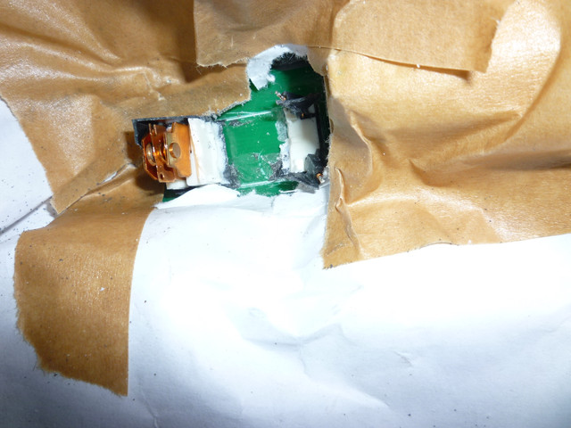
I found two broken capacitors on my (inop) lower board, C112 and C113. They are right by the 3 big cans next to connector L2A at J22. Does anyone know their values? They seem to have spit their guts out...any ideas on what might have caused that?
Electrically they are between the bridge output and + of the 3 big cans and parallel to diodes LLD1 and LLD2.

view
 
Never heard of those caps blowing before.

Those 2 are in parallel; i measured 1.95 nF for the pair, so i suspect that they are each 1 nF.

i couldn't see the picture; google wants a login so they are likely marked as private.
 
Sorry, just made the link public, you should be able to see it now.
Seems strange to me, too that they blew, but there was a distinct small plume of smoke from exactly that location when I connected the charging cabel last time.
 
Back
Top