The Troubleshooting and Repair for On-board Charger (OBC) Thread

Mitsubishi i-MiEV Forum

Help Support Mitsubishi i-MiEV Forum:

This site may earn a commission from merchant affiliate links, including eBay, Amazon, and others.
Arne said:
My failed components also are the 2.2µF cap on the lower charger board C106 (Okaya LE225 310V X2 2.2µF) and the big ceramic 4.7 Ω resistors R105 and R106. Did you find a replacement for the Okaya LE225 310V X2 2.2µF?
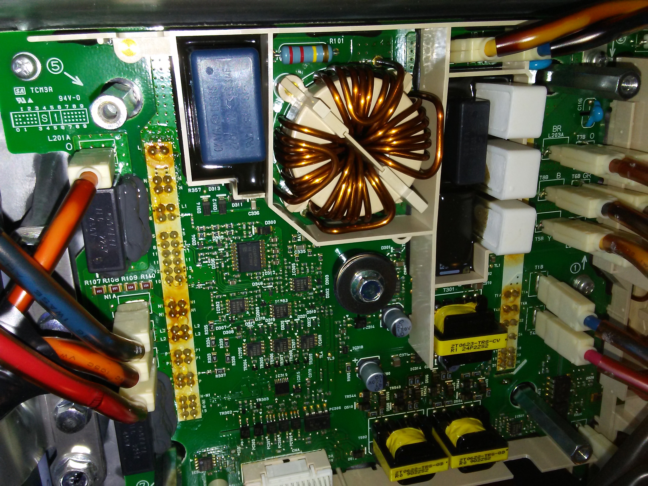
Let me make it abundantly clear from the outset that I am about as far from an expert on these things as anyone should be while still attempting such a repair. I am only half joking when I say I know only enough about electronics to be dangerous. I literally cook-booked my way through this repair, relying almost exclusively on the expertise of others who graciously offered their guidance in this thread. The only reason I attempted this is because I'm an engineer with experience in the mechanical aspects of electronics packaging, and therefore have had occasion to become familiar with some techniques used by electronic techs. Please consider my words here only as a record of what I did in my repair, not as advice. Also, my car doesn't get a lot of use, so I'm only at about 8 post-repair charges so far. But it's still acting perfectly normal.

With that disclaimer out of the way....

I used these capacitors: https://www.digikey.com/en/products...BcDaIMwE4EFoBOBWOdUBYxgAZ0CAHAga2QDsATEAXQF8g

Note that with all the parts I used I tried hard to find replacements with high maximum temperature ratings. I believe some of the original parts were rated at around 85 °C, but there have been too many clues suggesting higher temperatures in practice.

For the resistors I will try your solution of 2 fat 10 Ω resistors in parallel for the resistor part, in series with some 157 °C, 16 A thermal fuses (paired in parallel). Your solder job looks nice, but how did you do it in practice? Did you wrap one lead around the other once, solder the space in between and clip the rest of the lead? What did you use to refill the potting area?
I made sure to use exactly the resistor recommended by @coulomb, since he suggested it based on its impulse power absorption. I found it here: https://www.digikey.com/en/products/detail/ohmite/OX100KE/823902

I assumed the thermal fuse was meant to be in thermal contact with its resistor, so kept everything pretty tight. That meant the whole thing could be done using only the lead wires of the resistors and fuses. For each solder joint the lead connection is half a wrap and squeezed hard. I believe best practice is to avoid any lead bending at the point where the lead enters the ceramic block of the resistor, so all bends are a fine-needle-nose-plier's-tip-width away from the body. I presumed that practice is even more important for the fuses, since there are several discrete bits inside them with a bit of thermal wax being the most critical. And since the close quarters demanded by keeping the parts together also shortened heat paths, all solder joints were made with some needle-nose pliers clamped to the lead between the joint and component body as a heat sink. I used my fat and ancient $10 soldering iron, only long enough to heat the solder, and removed it an instant after the solder flowed. I checked the fuses for continuity afterward, but since they are in parallel it's possible I could have opened one of them. If so, the 16 A rating of the other should still be enough for proper operation.

For re-potting the repaired area, some have suggested using any non-acetic 100% silicone. (The acetic acid is corrosive and gives it a vinegar smell.) I was ready to use some GE 100% silicone that was advertised as acid-free, but noticed in the fine print that they specifically recommend against using it for electronics. So I ordered a tube of ASI 388 electronics-grade silicone. To be honest, it's less firm than I'd like. Especially for those built-up resistor and resistor/fuse assemblies, which are supported only by their lead wires. (It's probably fine and I'm over-thinking this.) If you go this route, apply the silicone in a manner that minimizes air pockets to maximize stiffness.

Like you I also noticed bent pins on the flat ribbon cable. How did you solve this? I think I'll order these (https://www.distrelec.be/nl/platte-flexibele-kabel-5mm-50-kernen-102mm-molex-153660541/p/30222361) as a replacement.
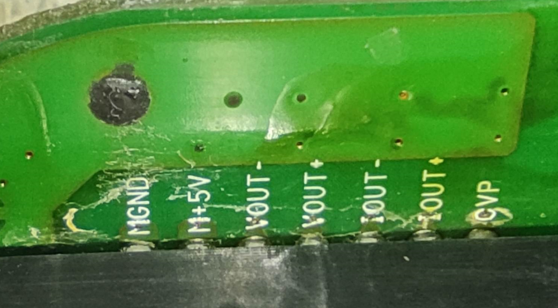
Mine weren't as bad as yours. (Are those solder balls on the contact pads of yours?) What I found with mine is that the contact pads are not adhered to the flex, so they probably snagged on something by handling. Because they weren't adhered, I could carefully nudge them back in place while using a 10X eye loupe to see what I was doing. I had to do that a couple times because I'm an amateur, and used an old towel to work on instead of a proper anti-static mat.

If you're going to use a non-original replacement for the flex cable, pay close attention to contact dimensions, materials and overall thickness to ensure it's compatible with the PCB connectors.

And finally, how did you read the trouble codes? I have a Vgate iCar Pro Bluetooth 4.0 (BLE) OBD2 reader. Can I use this to read and clear any remaining fault codes? Which app is recommended for this?
Not an expert, but there seem to be a variety of Bluetooth readers and compatible apps that read and clear OBDII codes. I got my OBDLink LX reader originally to work with Cani0n, but Cani0n stopped working reliably when I got a new phone. (It can't maintain Bluetooth connectivity with Cani0n, but works fine with other apps.) All work for this repair was done with the same reader, but working now with Car Scanner. It did what I needed, though I think the standard apps are limited for use with the i-MiEV. Only the dealer MUT3(?) tool will work for some functions.
 
hello everyone.
i have nissan leaf gen1 2012
i have problem inside of onboard charger. i change 4,7ohm resistor, it was burned. car charged 3-4 times and it burned again, i change this resistor, after 2-3 charge it blows, there is 3 pieces of 4,7 ohm 5W resistor, i have changed all of them wigh 10W resistors 4,7 ohm. thei also blows after 2-3 charge. can anybody tell me what may be a reason? other charger works in my car perfectly.
 
Did you check the little AC relay? or maybe it's just time to replace it. Check out this thread about the Laef OBC, Harvest the Leaves

If that relay does not engage properly (due to dirty or worn contacts, or any other reason), then the entire AC mains voltage is being carried thru the ceramic resistors. But they are not designed to carry that load for more than a brief 10-20 milliseconds.
It is the black rectangular device next to the white ceramic resistors and below the black capacitor, hard to see in this photo. Diode 301(near the bolt in the center) is in parallel to the relay coil and provides a place to apply 5V test voltage across the coil to actuate the relay. See page 1 of this thread for details on how to do this.
g2N30PI.jpg
 
Mouser has an Ohmite ceramic resistor for 89 cents, TWW5J4R7E, which should be a perfect fit for the non-fused resistor.

https://www.mouser.com/ProductDetail/Ohmite/TWW5J4R7E?qs=z79jz7UT1LesC4HOVACM7Q%3D%3D

Also if you want to roll your own, Caddock makes the MV series of axial lead resistors that can tolerate an energetic event energy of 37 to 150 J for 5 seconds (5x the power rating).
http://www.caddock.com/Online_catalog/Mrktg_Lit/TypeMV.pdf
 
kiev said:
Did you check the little AC relay? or maybe it's just time to replace it. Check out this thread about the Laef OBC, Harvest the Leaves

If that relay does not engage properly (due to dirty or worn contacts, or any other reason), then the entire AC mains voltage is being carried thru the ceramic resistors. But they are not designed to carry that load for more than a brief 10-20 milliseconds.
It is the black rectangular device next to the white ceramic resistors and below the black capacitor, hard to see in this photo. Diode 301(near the bolt in the center) is in parallel to the relay coil and provides a place to apply 5V test voltage across the coil to actuate the relay. See page 1 of this thread for details on how to do this.
g2N30PI.jpg


Thank for answer.
In my case charging starts, after 10-15 minutes or after 1-2 hour charging stops, and i see burned resistor. It ceramic resistor is for precharge, is it right? When charging starts relay works, but after several minute or hour resistor burnes, i think thet something stops voltage in coil of relay and burnes ceramic resistor, is this opinion right? I changed control board, but resistor burnes after 1-2 hour, as previous time.
Tonight i changed resistor, charging stoped after 1.5 hour, i changed resistor immedietly, after 10 minute burnet that one.
 
Yes you have an issue with the relay. There should be no current thru the resistors after charging starts--all the current should flow thru the contacts of the relay.

i suspect that your relay has damaged contact surfaces that are arcing and pitting, and the arcing has frosted over the surface with carbon soot residue which does not provide sufficient path for the full current, OR the relay winding has a high resistance and it heating up over time which causes the relay to open and blow the resistors.

You could try to measure the coil resistance at the D301 solder junctions. The diode will affect the reading in one direction, so for best results one side of the diode needs to be heated with a soldering iron and slightly lift the diode out of the circuit. Be careful with the tiny part, remove the center bolt for easier access, not too much heat and gently pry it up with a thin knife blade, etc. Or just use solder wick and remove the diode completely to make the measurement, then solder it back onto the board.
 
kiev said:
Mouser has an Ohmite ceramic resistor for 89 cents, TWW5J4R7E, which should be a perfect fit for the non-fused resistor.
It might be a perfect fit mechanically, but it's rated at 5 W where the original is rated at 7 W. The initial power through the pre-charge resistors, if connected to 240 V, is E²/R = 120²/4.7 = 3064 W. Much higher if the power happens to come on at the peak of the sine wave. The Mouser resistor seems to be able to handle the total energy (5x 5W for 5 s = 25x5 = 125 J, and half the energy in the capacitors is about ½CV² = 1/2 x 2.04 x 10⁻³ x 340² = 118 J spread over 2 resistors so 59 J each. But can the thin wire handle fast-boil kettle power for even a fraction of a second, or will it degrade over time?

Also if you want to roll your own, Caddock makes the MV series of axial lead resistors that can tolerate an energetic event energy of 37 to 150 J for 5 seconds (5x the power rating).
Those are film resistors, meaning that the peak power has to be dissipated by a film of resistive material. In this application, I think that composition resistors are called for; they use the entire bulk of the material for heat absorption. I've posted about my recommendation before; it's two Ohmite ceramic composition 10 Ω resistors in parallel, each rated at just 1 watt continuous. This pair replaces one 4.7 ohm resistor.
 
shuma89 said:
I will test resistence of relay on problematic charger, how many ohm-s would it be?
According to the datasheet that is archived below, the original relay coil should be 62 ohms plus or minus 10%. I vaguely recall a figure of 56 ohms.

Edit: https://forums.aeva.asn.au/download/file.php?id=5663
 
I've had a small win with the 2010 charrger that I'm repairing. Long ago I attempted to get CAN packets out of the charrger, but didn't get a peep, not knowing the magic CAN bus incantations to wake it up. But I think it was one of Piev's posts a week or so ago gave me that information, and all other avenues have hit brick walls, so I tried again tonight. I set everything up and sent the two magic CAN frames, but nothing came back. Darn.

Then I noticed that sometimes the green activity light on the CAN dongle would light up as if there was traffic. But there was none. Aha, different CAN bus speed? Surely not. I tried other speeds, but any change from 500 kbps and standard frames made the activity go away. So why was I not seeing anything? The CAN dongle was working just a few days ago, surely it hadn't gone faulty. And besides, changing the speed or CAN frame type was making a difference.

To cut a long story short, I had double clicked on the icon I set up to run the USB-Can program, and Windows 11 (bless its heart) only needs a single click these days, So it was running two instances of the CAN application, and both were connecting to the dongle! The other window, which was behind the first one, was receiving all the data! Very strange.

So now I see the following traffic over and over, as soon as the charrger is powered up. It doesn't have to wait for the enabling packets; maybe it somehow remembered them? Also, I get the "decimal point" on the 7-segment LED blinking, and also one of the five LEDs is on (perhaps it was the one associated with PWM of the PFC stage, I don't recall). As far as I can remember, none of that activity was happening last time.

One thing that I noticed is the third byte (byte 2) of the 389 packet, which various sources quote as "Charge DC input current", but I suspect must represent charrger output current to the battery and HV loads (heater, air conditioner). Maybe the sensor is faulty, and maybe that's what's stopping the charrger from working. But I think it's more likely that we just don't know what that byte really means.

The CAN data:
Code:
NO    Direction  Time Scale        Frame Type      Frame Format        Frame ID    Length         Data 
0     Receive     20:10:35:561     Data frame     Standard frame     00000389     8     01 01 ff 39 39 00 00 00
# Above: 2V battery, 1V AC in, Charge DC input current FF!!??, 17°C?, 17C, 0, AC in current 0A
# "Charge input current" may be the DC charrger output current, tenths of amps DC. Bad sensor?!

1     Receive     20:10:35:597     Data frame     Standard frame     0000038a     8     38 00 00 00 00 00 00 00      
# Temperature x1 (16°C?), next is zero (not present or faulty?), B3 = 0 so EVSE not present

2     Receive     20:10:35:661     Data frame     Standard frame     00000389     8     01 01 ff 39 39 00 00 00      
3     Receive     20:10:35:694     Data frame     Standard frame     0000038a     8     38 00 00 00 00 00 00 00 
# These repeat every 100ms
     
4     Receive     20:10:35:725     Data frame     Standard frame     00000568     8     04 00 00 01 00 00 00 40      
# This is the interesting one! Undocumnted, 3 bits are on. Maybe the first bit (bit 2) represents diagnostic code 06, AC input voltage abnormal!
# If so, other bits might represent codes 32 and 58, which would be "Charging current limited (input voltage decrease)" and way past the end.
# 39 would make more sense: "Power factor correction (PFC) circuit output voltage abnormal" but maybe it's not on because 06 is on.
# Every 200ms, so appears last in a group of 5 (389, 38a, 389, 38a, 568).


5     Receive     20:10:35:760     Data frame     Standard frame     00000389     8     01 01 ff 39 39 00 00 00      
6     Receive     20:10:35:795     Data frame     Standard frame     0000038a     8     38 00 00 00 00 00 00 00      
7     Receive     20:10:35:862     Data frame     Standard frame     00000389     8     01 01 ff 39 39 00 00 00      
8     Receive     20:10:35:894     Data frame     Standard frame     0000038a     8     38 00 00 00 00 00 00 00      
9     Receive     20:10:35:927     Data frame     Standard frame     00000568     8     04 00 00 01 00 00 00 40  
# Repeats. One temperature went up by 1°C by the end of the logged data (about five seconds worth).
So: 389 and 38A are the expected CAN bus IDs for charrger activity, but 568 is new and as far as I know totally undocumented. Note how nearly all the data are zeroes, except for three bits that are set, My hope and guess is that this is the packet that the charrger sends to the EV-ECU to tell the latter about abnormal conditions, and is possibly the mechanism whereby the EV-ECU stores charrger related trouble codes, and perhaps also the all-important charrger related diagnostic codes.

My thought is that at least for the first several codes, successive binary bits left to right represent the decimal codes, e.g.
0x80 01 01Output voltage abnormal
0x40 02 Load connection abnormal (main battery not connected)
0x20 03 Output current abnormal
0x10 04 Control power supply voltage abnormal
0x08 05 Not used
0x04 06 AC input voltage abnormal
...
Second data byte:
0x80, 0x40 09, 10 not used
0x20 11 Voltage command abnormal
0x10 12 Current command abnormal
...
That's a wild guess. The last bit that is set is way past the end of the documented code list, which ends at code 45, so maybe the last 2 bytes mean something else.

So I was keen to plug in the charger (not trivial on the bench) to see if the first bit would go away with non-abnormal AC present. Alas, I had to remove some screws to gain access to the AC-in quick connect tabs, and dropped a screw into the hole where one of the cables to the DC-DC comes through. Everything I tried just pushed the screw further down into the DC-DC. So I'll have to take that cover off to retrieve the screw; it's too late and cold (for sun-spoiled Queenslanders) so that will have to wait till tomorrow.

I'm wondering if I can safely provoke some of the errors so that I might be able to learn the mapping from this CAN message to diagnostic codes, if indeed that's what it's for. If so, I might be able to figure out what the diagnostic code is with no particularly fancy hardware. This could be a boon for repairs into the future.

Postscript: I was about to send this message, when I remembered that I have a log of normal charging, so I can compare. Alas, in that log, there were 0x568 packets with exactly the same data, just every second or so instead of every 200 ms as I was seeing on the bench. So that shoots down the diagnostic code theory, I think. At least we know that 0x568 originates from the charrger.

On the other hand, I now see the 0x389 packet probably represents charge current into the HV battery. There were two values for this byte in the good charging session: 0x47 (71 or 7.1 A) and 0x3B (59 or 5.9 A). The AC input current barely changed at all, so my guess is that there is an intermittent HV load that is present some of the time and not others, e.g. air conditioning or DC-DC. Actually, I measured only 102 W difference between AC input power and DC output power (at the higher of the two output currents), so that barely covers expected losses, and leaves no room for DC-DC consumption. So that sensor may be outside the charrger, perhaps in the battery itself. If so, the charrger would be expecting CAN packets telling it what that current is. That might be the reason for the FF in the DC output current byte. Though it seems strange for the charrger to report a measurement that is coming from elsewhere. I suppose it makes a little sense if the charrger is relying heavily on this data. For example if the EVSE is signalling that plenty AC current is available, then the charrger is not limited my AC-in power, so it has to limit power to its own rating (3.6 kW or whatever it is). But then I'd expect it to need to see all DC load current, not just current into the battery. It would make more sense to me to put a sensor inside the charrger.

Which means I haven't found the diagnostic code, and I may need to feed the charrger more CAN packets to keep it happy.
 
ad39a85d892d61e753ff03f899ad5fa9.jpeg


It is picture with thermal camera.
52⁰ is ralay temperature, 98⁰is driver transistors temperature, is this normal?
In my mind difference of relay and driver temperature 50⁰ is very high. Is this normal?
 
Yes it is normal, extremely hot but normal. See the miev thermals here, https://myimiev.com/forum/viewtopic.php?p=36747#p36747

But i am surprised that the drive transistors run so hot.
 
195553a5b4830aee0f8f40cf748c7c5c.jpeg


It is after 2,5 hour of charging.
If drive transistors have problem they can work hotter then usual? I think that relay have not problem, if drive transistors work hotter then usual, it can make effect relay temperature also and may be it reaches 100⁰ or more?
 
coulomb said:
I've had a small win with the 2010 charrger that I'm repairing.
... so it has to limit power to its own rating (3.6 kW or whatever it is). But then I'd expect it to need to see all DC load current, not just current into the battery. It would make more sense to me to put a sensor inside the charrger.

That's great news to hear you've made contact thru the CAN buss, and you are blazing the trail.

Not sure about your version but on the 2012 there is R232, a 0.008 Ohm sense resistor in the HV DC Output section that is measuring the total output current of the charger, which would include any DCDC input current plus Pack charging current. If you could find that equivalent resistor on your boards, then you could introduce a fault by running some current thru it while interrupting the AC mains faston connections to prevent charging.

i don't remember if there were ever posted some xray pictures of all the mini-waffle plates..?
 
@shuma89,
What are those extra wires near the AC input and the capacitor next to the relay? Maybe move those wires to see what is getting so hot on the board, and post a regular photo to show everything.

Can you get a thermal image from a different angle, maybe directly above the driver section?
 
Thous extra wires are for capacitors, one capasitor was blown near the relay, 2.2 mkf
My car is Nissan leaf 2012 and best angle for photo was that angle, what I made photos.

Tonight the white ceramic capasitor was blown. It was second charging after it was changed by me.
May the reason be from control board? Or voltages from relay control parts? What parts are controlling the relay?
 
kiev said:
@shuma89,
Can you get a thermal image from a different angle, maybe directly above the driver section?
I can't help with another thermal image, but I can show ordinary photos. It doesn't seem to be an identical model, unfortunately.

Overall, for context:

file.php


The bottom board:

file.php


You can see that the AC input capacitors are prone to oozing; I have seen other photos of them more or less exploding:

file.php


The area that gets to 98°C seems to be between the transformers, and seems to be just SMD driver transistors, although it's possible that these SMD transistors drive something stronger under the board, though I doubt it; presumably these transistors only drive the isolating transformers for the IGBT gates:

file.php


98°C does seem way too hot for these transistors. It would be good to know if it's the driver transistors or diodes or both that are getting so hot.

Edit: As for what else is getting hot near the AC input wires, that's a really good question. There really should not be anything getting hot there, at least from my and other photos.
 
i think that your relay contact surfaces have been damaged by the interruption while it was carrying the full load current.

You can see that the current is substantial by the glowing inductor windings in the foreground of the IR photos.

Every time that a resistor has been blown by a relay trip, then the relay contacts will also have suffered some arcing damage.

The relay control signal is created on the upper control board and passed down thru the white wire harness. Since it happened even after swapping the upper board, indicates to me that the upper board and relay supply is not the issue. That leaves either a dropout of the 12V supply to the OBC due to an old, weak, or worn out 12V battery, or some other control signal interruption such as a defective EVSE unit, or a defective relay as the likely root cause.
 
I thought I might learn something about how OBC PIDs get converted to "real" CAN bus messages, by using an old EV-ECU:

file.php


Alas, I could not coax any life out of it, other than drawing a bit of current. The current twitched encouragingly as if it was sending a bunch of CAN bus messages or doing something else that drew a few milliamps more current every half second or so, but that was it. I guess there is a reason that this EV-ECU was given to me for free.
 
kiev said:
Not sure about your version but on the 2012 there is R232, a 0.008 Ohm sense resistor in the HV DC Output section that is measuring the total output current of the charger, which would include any DCDC input current plus Pack charging current.
Actually, that's a really good point, thanks! Indeed there must be a shunt there. I think that these are the pins up from the lower PCB at the input of the measurement op-amps:

5KPOOds.png


I don't remember if there were ever posted some xray pictures of all the mini-waffle plates..?

There was an X-ray, but only of the AC input module, and I'm 95% sure that the input module is working OK. It was a few pages after the start of PhilSuth's early 2010 repair. Perhaps you could add Phil to the index; I found it hard to find his posts just now.
 
Back
Top