The Troubleshooting and Repair for On-board Charger (OBC) Thread

Mitsubishi i-MiEV Forum

Help Support Mitsubishi i-MiEV Forum:

This site may earn a commission from merchant affiliate links, including eBay, Amazon, and others.
What DTC does it throw now? i hope it is a different code.

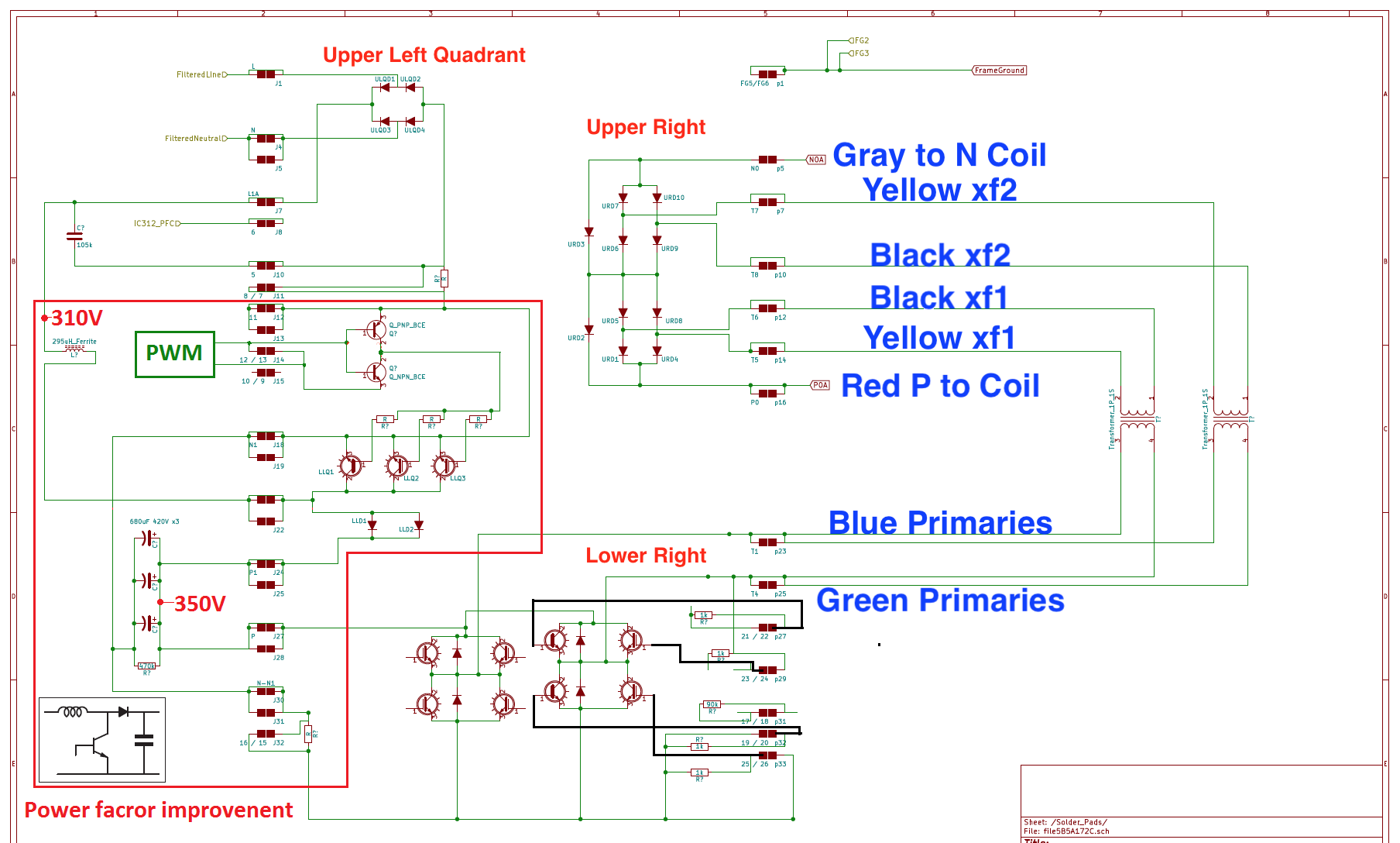
In post #2 on page 1 is a section with a schematic of the waffle plate soldered under the power board. Also is a link to the diode drops that can be measured at those 72 solder joints while still on the board.

Other ideas if the waffle plate measures okay:
Sometimes when the snubber caps explode they splatter molten metal onto the bottom of the control board and short out pins on ics.

Did you check the continuity thru the installed flat ribbon cable from the connector pins on the power board up to the connector pins on the control board.

The 12V battery voltage should come up to 14.4 now when it goes to READY would indicate the DCDC is working okay.
 
Hi m8s,

So, short what i done:
-change all caps, resistors.
-checked fuses, relays

My iMiev starting charging and after few seconds stops and silient :/

I see 14.5V and above 400V on high voltage side.
No DTCs in OCM, BMU, MCU, EV-ECU, and anyCMU units.
I have no more ideas.
Thanks for any response.
 
Since you measured pack voltage reading "above 400V", it sounds like the BMU is reporting a Full Pack, so the EV-ECU decides that no charging is needed and no DTC will be thrown?
 
kiev said:
What DTC does it throw now? i hope it is a different code.
Unfortunately, it is the same single code:
P1A12 - OBC abnormal stop

kiev said:
In post #2 on page 1 is a section with a schematic of the waffle plate soldered under the power board. Also is a link to the diode drops that can be measured at those 72 solder joints while still on the board.

OK, I started doing some measurements but got unexpected readings, maybe I am misunderstanding what to do.
I am looking at this picture:
SBC5zA0.png

Based on the Upper Right section, I should be able to measure
- URD7 diode between solder points N0 and T7
- URD10 diode between solder points N0 and T8
If I understand correctly, both of these should give near-zero Ohm one polarity and infinite (disconnection) in the other.
However, I am getting <1 Ohm on N0-T7 in both polarity directions and disconnect between N0-T8 in both polarity.

So something is not right -- quite likely my understanding is wrong...

Thanks for all the advise!
 
ZsoZso said:
Based on the Upper Right section, I should be able to measure
- URD7 diode between solder points N0 and T7
- URD10 diode between solder points N0 and T8
If I understand correctly, both of these should give near-zero Ohm one polarity and infinite (disconnection) in the other.
Close. But you don't use a resistance range on your multimeter for this, you use the diode function. The resistance ranges try to use low voltages that don't turn on semiconductors, while the diode ranges use at least 2 V so that semiconductors (e.g. silicon diodes, even LEDs) do conduct.

So on a resistance range, it will read more or less open circuit in both directions. On the diode range, in the forward direction (red, positive lead to the anode), you should read around 0.4 V for power diodes, or 0.6 V for signal (lower power) diodes. IGBTs can be tested by their free-wheeling diodes, again around 0.38-0.43 V.

However, I am getting <1 Ohm on N0-T7 in both polarity directions and disconnect between N0-T8 in both polarity.
Less than one ohm of resistance is a common reading for failed semiconductor junctions; they tend to fail shorted because the silicon melts and changes properties drastically.

But you have to be careful with transformer windings and the like that can mask the true reading. Is this with anything still connected to the Waffle Plate™? Even with the transformer windings still connected, However I would probably not expect a low resistance reading between N0 and anything else.
 
There is a diagram showing the expected diode voltage drop measurements at the solder joints with all the fastons tabs disconnected to remove the external circuit paths:

https://myimiev.com/forum/viewtopic.php?p=40562#p40562
 
I just bought a 2011 i miev that doesn't slow charge. only chademo fast charge.
I opened the OBS and found signs of heat on the cover, the two black relays? in the "dog house"? on the lower board looks blown. one snubber cap is lightly cracked. I think I will replace everything in the lower dog housed, except for the coil.
The problem is I cannot find the two large ceramic resistors anywhere on eBay/Aliexpress. Does anyone have a link/product name/code to help find them?

The top boards dog house also has some hairline cracks in the caps, and the relay looks blown also here(hole in the rubber next to it).
I'm thinking I will replace caps and relay also here..

The three large caps have wrinkled plastic on them, but look pretty flat on the top. Any point in changing them?
Or is there an easy way of testing them?

Links to resistors and other tips are greatly appreciated :)
Im not an electronics wizard, just a technician with a soldering iron :lol:

AL9nZEU1uRg5p3A2RVL0sSwIZ1yFKq3bg3Fly0TpOEAFNGQKGmzhZKcgVYKRs1hI8CH-M-249jk49BPlzD3HgfDsp_ScAy-MeTGhxQUXfoskPYltA6S2y89oM01907x51XQ7mnBfF18S7X1isRuBDs9XX4X4wg=w1216-h912-no


AL9nZEWxtI2HM_-z6Q7O1WbhONdh3BK7NwNEzBoWGzqJNXxvN0IpYOeBauQmECBXf0xQPDsoSibScu2G5lTPQku80zZu3dpuECwDzfNdktNKIURKhG2c0J7Si6bqUT3Q_7Akdl1677Fe64oIzarFqCJ87d8Trg=w1292-h969-no
 
The ZNR in the little potted area on the upper control board looks cracked so it has likely suffered a massive over voltage event. The other device in that potting is an AC capacitor not a relay.
What is ZNR surge absorber? "ZNR" stands for Zinc-Oxide Non-linear Resistor, the product name of a voltage-dependent resistor (registered trademark) developed by Panasonic (formerly Matsushita Electric Industrial) in 1968. This product is generally called a zinc oxide (ZnO) varistor or metal oxide varistor (MOV).

Before doing anything on the lower power board i would recommend that you use the diode check function of your meter and check all the diode drop voltages at the solder junctions to the waffle plate. The schematic is shown in a few posts above this one and the expected voltages are found in a link in my previous post to this one. Also nearly everything is identified or linked in posts on page 1. If the waffle plate is defective then it will need to be replaced or the other repairs will not be effective.

From your photo, Check the resistance on the lower board from the white wire to the solder junction on the waffle plate marked "N". It should read about 10 Ohms if the white ceramic pre-charge resistors are okay. There is a link to testing the AC relay (next to the two blue snubber capacitors) on page 1, which will cause the resistance to go to zero when the ceramics are bypassed. Be careful and mind the polarity when applying power to diode D301 to energize the relay.

The AC capacitor above the ceramics has leaked out some gray matter and is obviously defective.

The lower snubber capacitor appears to be darkened or a different shade of blue to my eyes, as if it has suffered some thermal distress. Those two should be replaced while you are in there, as long as the waffle plate is okay.

There are 72 hefty junctions to desolder the waffle plate to access the bottom side if you decide to go that route. If only capacitors are bad then some folks have replaced them from the top side.

To me it appears that your failure is more likely on the AC input side of the OBC rather than the HV DC output side. If the fuse in the MCU is okay then the snubbers haven't blown yet but one appears to be close to letting go.
 
Thanks for the tips.
Great info, there.

I will do some measurements for the waffle plate.

The MCU was as you guessed, not blown. But seeing how they often end up, I wouldn't close this back up without replacing the snubbers 😅
 
kiev said:
There is a diagram showing the expected diode voltage drop measurements at the solder joints with all the fastons tabs disconnected to remove the external circuit paths:

https://myimiev.com/forum/viewtopic.php?p=40562#p40562

Thank you.

I have bought a cheap multi-meter with diode function, fully disconnected and removed the board and gone through the measurements.
The good news is, that the wrong directions all read disconnect, and the correct directions all measure some voltage drop similar to the values on your diagram.
The bad news is that the values don't match exactly, e.g. N0(+) to T7(-) I get 0.41 instead of 0.37 and N0(+) to P0(-) I get 0.95 instead of 0.747.
For the upper left quadrant diodes, I get 0.51 instead of 0.47 or 0.48.

Although, I suppose the differences might be due to the inaccuracy of my cheap multi-meter.
 
ZsoZso said:
I suppose the differences might be due to the inaccuracy of my cheap multi-meter.
It could well be that, and/or temperature, different parts, and so on. I'd say the Waffle Plate™ is probably OK from that.
 
Cisq said:
My iMiev starting charging and after few seconds stops and silient :/
Did you check that 230 VAC arrives inside OBC for at least few seconds after pluging Yazaki charging connector? (Charger and charging power-path is OK)

Cisq said:
I see 14.5V and above 400V on high voltage side.
Strange. Old-type batteries have 88 cells x 4,10V = 360,8V, the newer ones have 80 cells x 4,10V = 328V
 
hello!

i have the same problem as few post ago. i have a 2011 i miev that doesn't slow charge. only chademo fast charge. i changed the 4.7 ohm 5w resistor and the problem was solved for 2 days. now, that resistor is broken again and if i change it is broken immediately. a little help, please?
 
Hello everyone from sunny Finland :))
I'm asking for help because I'm stuck.
Citroen c-zero does not go into ready mode, the 12 V battery charging lamp and the low brake fluid level lamp are on.
no 12v battery charger.
the OBC unit does not communicate with the diagnostic equipment.
checked the OBC power according to the instructions:
http://mmc-manuals.ru/manuals/i-miev/online/Service_Manual/2012/54/html/M154950190002101ENG.HTM - everything is ok
all relays are ok.
fuse MSU ok
opened OBC: all fuses on the top and bottom board - ok
there are no damages.
I wanted to add a photo, but did not understand how to do it:((
any ideas where to go next?
kind regards
 
treisutedoi302 said:
hello!

i have the same problem as few post ago. i have a 2011 i miev that doesn't slow charge. only chademo fast charge. i changed the 4.7 ohm 5w resistor and the problem was solved for 2 days. now, that resistor is broken again and if i change it is broken immediately. a little help, please?

Howdy and welcome t302, it sounds like your AC relay is not engaging and the resistor is being forced to carry the AC input power for too long a period (which it was never designed or intended to do).

The white ceramic resistors are pre-charge resistors to handle the initial inrush current into the large capacitors on the power board. After a brief time period the AC relay is supposed to engage and bypass the resistors and carry the bulk of the AC input to the waffle plate under the power board.

See posts on page 1 for pictures and links to other posts such as how to test the AC relay, etc. The relay may be defective or the 5V supply voltage created on the upper control board may be missing or some other fault is preventing the 5V from reaching/switching the relay coil.

One of the white ceramic resistors has an internal thermal fuse, the other one is purely a resistor, check them both, but do not energize the OBC until you have cleared the AC relay issue or the resistors will continue to fail.
 
Slava said:
Hello everyone from sunny Finland :))
I'm asking for help because I'm stuck.
Citroen c-zero does not go into ready mode, the 12 V battery charging lamp and the low brake fluid level lamp are on.
no 12v battery charger.
the OBC unit does not communicate with the diagnostic equipment.
checked the OBC power according to the instructions:
http://mmc-manuals.ru/manuals/i-miev/online/Service_Manual/2012/54/html/M154950190002101ENG.HTM - everything is ok
all relays are ok.
fuse MSU ok
opened OBC: all fuses on the top and bottom board - ok
there are no damages.
I wanted to add a photo, but did not understand how to do it:((
any ideas where to go next?
kind regards

Howdy Slava from Finland,

Here are a few ideas for you.

What is the age and condition of your 12V starter battery? A weak, old or worn out 12V battery can cause a multitude of faults and issues with an EV. It might read normal with no load but sag too low when the loads are applied.

The other idea is that the fuse in the Motor Control Unit (MCU) has blown. This would cause the faults you have described, i.e. lack of READY, lack of 12V charging, lack of OBC charging operation.

Do you hear the usual relays and contactors in the pack clacking when you try to start the car or when plugging in the EVSE handle to charge the car?

If possible get an OBDII scan tool or dongle to read out the DTCs to help identify the troubleshooting path.
 
thanks for the response.
the car came to me with a completely empty 12v battery.
I connected another one along with charging to do diagnostics
at the first error reading, the ECM_EV block issued the following codes:
P1B31 - brake fluid pressure sensor fault
U1113 - DTC to be ignored
P1A15 - Capasitor charging fault Charging time too long
after removing the errors, only U1113 remained.
UOCSrkS

utJdzkW

utJdzkW

t8CGMWF

eU3CfHq

at the same time, in the live data I see 4.44 V Traction battery OBC signal voltage and the OBC unit does not get any response - not connected.
Today I will remove and completely disassemble the converter.
 
kiev said:
Slava said:
Hello everyone from sunny Finland :))
I'm asking for help because I'm stuck.
Citroen c-zero does not go into ready mode, the 12 V battery charging lamp and the low brake fluid level lamp are on.
no 12v battery charger.
the OBC unit does not communicate with the diagnostic equipment.
checked the OBC power according to the instructions:
http://mmc-manuals.ru/manuals/i-miev/online/Service_Manual/2012/54/html/M154950190002101ENG.HTM - everything is ok
all relays are ok.
fuse MSU ok
opened OBC: all fuses on the top and bottom board - ok
there are no damages.
I wanted to add a photo, but did not understand how to do it:((
any ideas where to go next?
kind regards

Howdy Slava from Finland,

Here are a few ideas for you.

What is the age and condition of your 12V starter battery? A weak, old or worn out 12V battery can cause a multitude of faults and issues with an EV. It might read normal with no load but sag too low when the loads are applied.

The other idea is that the fuse in the Motor Control Unit (MCU) has blown. This would cause the faults you have described, i.e. lack of READY, lack of 12V charging, lack of OBC charging operation.

Do you hear the usual relays and contactors in the pack clacking when you try to start the car or when plugging in the EVSE handle to charge the car?

If possible get an OBDII scan tool or dongle to read out the DTCs to help identify the troubleshooting path.

when the key is turned, there is no click of the relay, only the sound system fades out
 
removed the converter, opened the bottom cover.
no visible damage. fuses are all ok.
direct wire to 12v battery is ok.
MCU fuse that located under smal lid on invertor - ok
removed the converter, opened the bottom cover.
no visible damage. fuses are all intact.
direct wire to 12v battery is ok.

any idea?
 
I continued my research:
checked the transistors under the bottom lid - it's ok.
I checked Can - the signal is good.
Hnco8cL

then I noticed a pattern:
when I connect everything - there are three errors and a yellow service lamp.
P1B31 - brake fluid pressure sensor fault
U1113 - DTC to be ignored
P1A15 - Capasitor charging fault Charging time too long
after deleting errors, the yellow lamp goes out, I try to transfer the car to Ready, I HEAR THE RELAY, but the yellow lamp lights up again and the ready mode is unreachable.
I read the codes and see again
P1A15 - Capasitor charging fault Charging time too long
Is it a problem with the inverter? but the diagnostics of errors on it does not give out, and I don’t understand why the OBC unit does not get in connection with diagnostic ???
 
Back
Top