The Troubleshooting and Repair for On-board Charger (OBC) Thread

Mitsubishi i-MiEV Forum

Help Support Mitsubishi i-MiEV Forum:

This site may earn a commission from merchant affiliate links, including eBay, Amazon, and others.
The P1A12 DTC indicates an abnormal stop occurred during charging, but there could be numerous causes and it doesn't point to any specific circuit.

The MUT tool is required to read the specific OBC fault code (listed on page 1) that identifies the problem area and triggered the DTC.

Unfortunately the OBC is too smart to allow bench testing by simply connecting AC to the leads. Some sort of simulator would be needed to provide all the control signals necessary to set the current level and start the charging, plus a HV battery would be needed on the output side as a load. Let me know if you figure out a way to do this, i need it too.
 
Hi All,

I have a 2011 i-Miev that stopped charging a couple of days ago. Tried to make an appointment at the local dealer, the first available time is in 2 weeks, so I got an iCarsoft reader to try to figure out what is the problem.
When I plugin the AC charger, the car shows the icon for the plugin but does not charge.
It also shows the red battery icon as well as the yellow drivetrain error (car icon with exclamation mark).
I only have 3 bars of charge left so I am not sure I could reach a DC fast charger to test if that works.

Anyway, the iCarsoft code reader got me the following error codes:
U1109
U1160
P1B18
P1AA7

It also has messages about EV-ECU signal time out and
EV-MSG lost (MCU)/EV CAN timeout

Could anyone help me understand what these codes / messages mean ?
Thank you very much!
 
Sorry to hear you have trouble.

From the FSM there are troubleshooting steps for all the trouble codes, for example in your case
=====
CODE NO. P1AA7: EV-ECU SIGNAL TIME-OUT
BMU
The signal sent by the EV-ECU through the CAN cannot be received.
=====
CODE No. P1B18 EV-ECU LOST
EMCU
If the CAN data from the EV-ECU cannot be received for 0.3 seconds or longer, the EMCU will set the diagnosis code No. P1B18.

PROBABLE CAUSES
The CAN bus line is defective.
Malfunction of the EV-ECU
=====
Which all sounds scary but none of these is related to the OBC.

The Uxxxx codes are related to CAN buss errors, and from multiple instances over the years we have found that an old, weak or worn out 12V starter battery can cause a multitude of faults such as you have found. Fully charge it or replace it with a new one that you also fully charge. The chances are very good that all these codes will clear and you will be fine. (Assuming nobody has been rooting around under the back seat with the EVECU and BMU connectors; if that has occurred then all bets are off).
 
Thanks for the explanation of those codes.
I have replaced the 12V battery and put in a fully charged new one.
Now, I got 2 new codes:

P0A09 DCDC converter fail
P1A12 On board charger abnormal stop
 
Did the other codes go away?

Based upon those 2 codes, i suspect that the fuse under the access cover in the Motor Control Unit may be blown. If so then the puzzle becomes why did it blow. Also if so then the snubber capacitors on the power board in the OBC are likely blown too.
What happens when you plug in the EVSE to charge--any relays clacking or lights on the dash, does it attempt to charge but then stops, does the contactor in your EVSE unit engage, etc?

Has there been any mains power outages while the car was charging, lightning storms, someone snatching the EVSE handle out of the socket while charging, etc.

What was the voltage on the old 12V, was it fairly worn out or old?

Will your scan tool read the OBC error codes, e.g. 26 charging current limited due to excessive temperature.
 
If the DCDC doesn't start for 4 seconds or more after being commanded ON.

P0A09
When the DC-DC converter drive stop state continues for 4 seconds or longer while the DC-DC converter driving approval is underway, the diagnosis code No. P0A09 will be set.

Probable cause
Damaged wiring harness or connector(s)
Malfunction of system cooling
Malfunction of the DC-DC converter
Malfunction of the EV-ECU

=====
The P1A12 code
When the diagnosis code (except for No. 26, No. 32) is set to the on board charger, the diagnosis code No. P1A12 will be set.

Any OBC fault except 26 and 32 will cause this DTC.
 
Taken apart the OBC,.
Looks like I got a fried capacitor:
https://photos.app.goo.gl/pzE6NvqwundQ5w489
hmmm, need to figure out how to post image, google photo link does not seem to work...


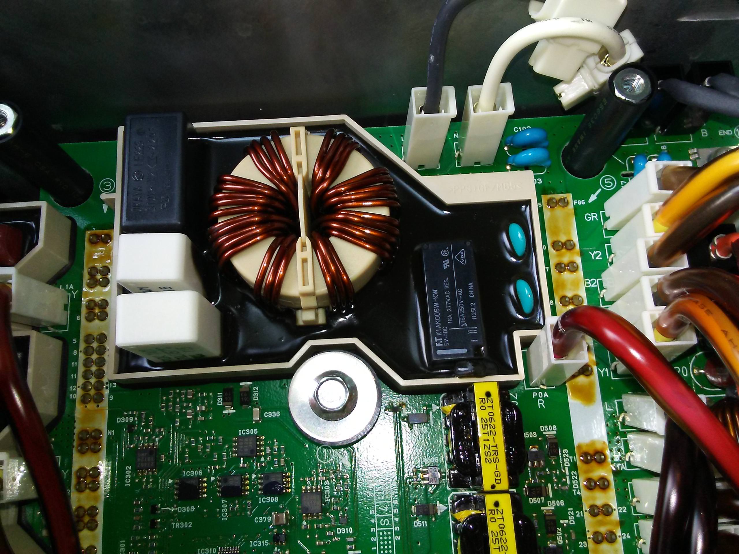
It is the top blue one in the doghouse surrounded by the black conformal coating on this picture (this is not mine, copied from upthread):
H8HMxD3.jpg


The old errors are still there too.
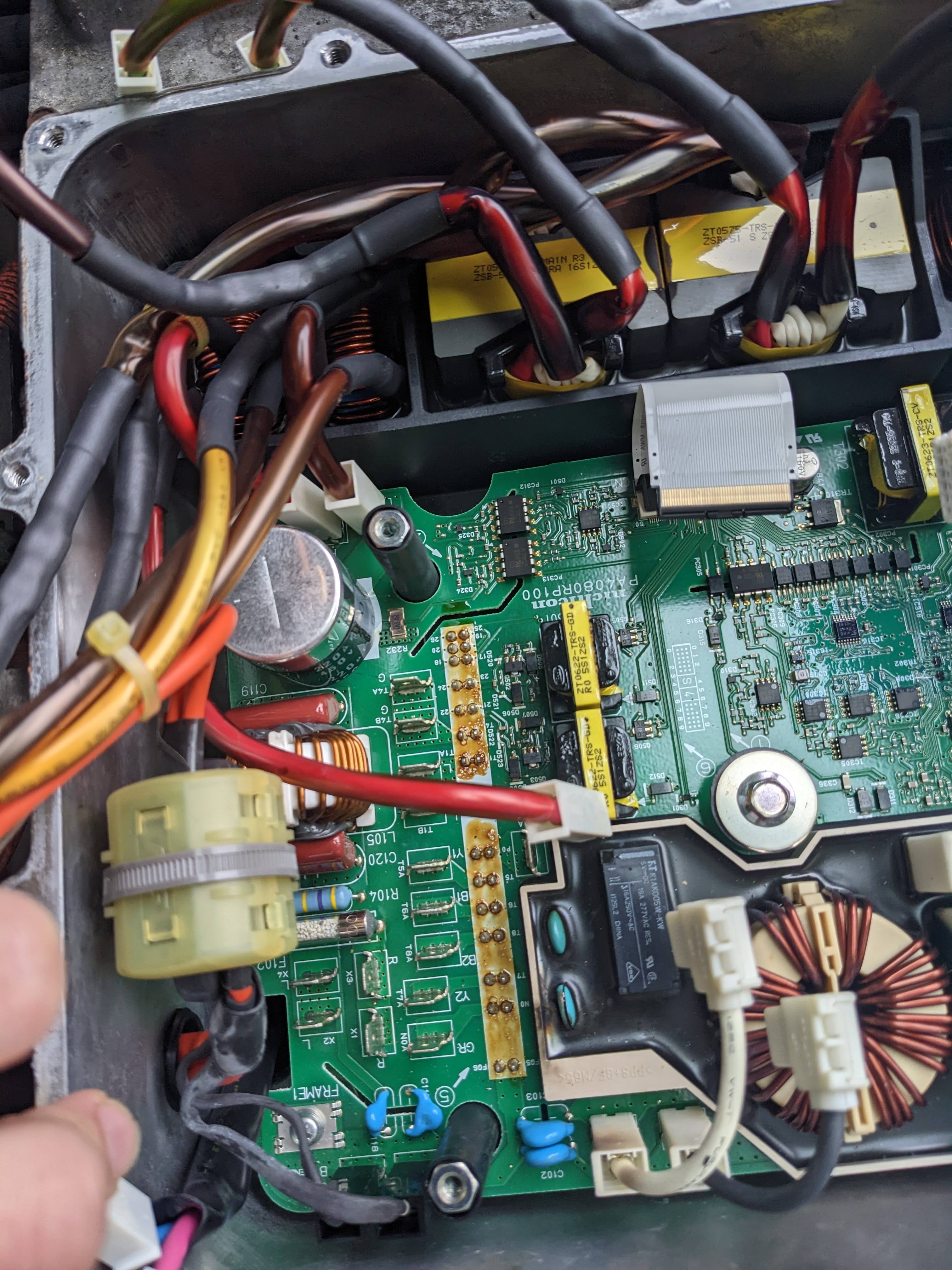
The communication problems are probably due to the broken data connector (1 pin is missing):
https://photos.app.goo.gl/fVEcwGe3Ywp7txx29
That pin just fell off when I was lifting the board up.
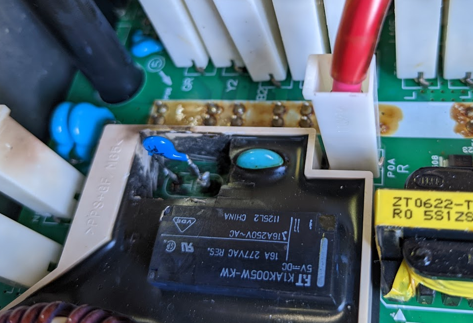
The old battery was a bit low (60% SOC, was reading 12.8V), but it seems to be still OK, I just charged it up without problem.
So I think it was just low because it did not get charge due to the DC-DC not working.
 
Yes if one of the blue snubber caps has blown, then the fuse in the MCU will be also, and the DCDC will have no power to work and charge up the 12V battery. Check the diode drops in the waffle plate first. If the plate has damage then that is more serious.

[edit Did you find any spattered metal from the blown capacitor on the control board?

AL9nZEUirpOMX4NahRDA1pg8Ap2h2fs8GIDx14rFkN8G4ehY67LuRswLPXfTccEiv-D8e7T0v8G74yn_9I__TVqqwUWl_TEjn9XguzWYfdMpWOoyFQ_6ZCyNKoAPLBUsPoGdf6E0qT-YFiDlucMXjpXomcw9TQ=w1540-h1154-no
 
ZsoZso said:
need to figure out how to post image, google photo link does not seem to work...
With Google photo, it is really hard to find the URL of a photo, and if you do, it's really long (like 1000 characters), and if you use it, you find that the URL changes in a few days and the link is bad anyway. Google is a small family run business, and can't afford to host everyone's photos :evil: Use imgur.com instead.

The old battery was a bit low (60% SOC, was reading 12.8V), but it seems to be still OK, I just charged it up without problem.
So I think it was just low because it did not get charge due to the DC-DC not working.
Yes, that sounds quite OK, given that the DC-DC would not be working. You'll have to source a replacement fuse; read the index of this topic for details.
 
kiev said:
... but never seen it blow the connector right off the board.
I think he's desoldered it (a really neat job, bravo), because one pin is missing. It might be difficult to source a replacement, but perhaps an unused pin could be moved into place?
 
duh i wasn't thinking right about losing a pin vs connector, or the great desoldering job. i could try to remove one from a damaged board but don't know if i could do it that well.

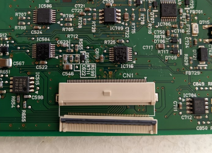
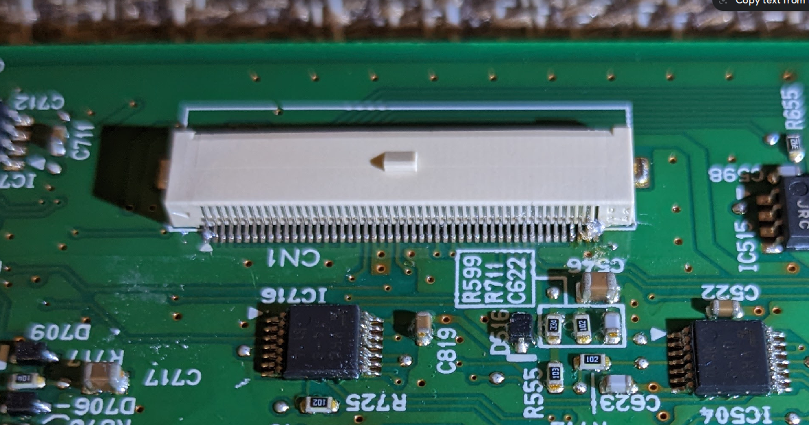
The missing pin looks to be pin 41, which is used in the current feedback circuit. See the bottom half of this post for previous notes and discussion with schematic:
CN1 Pin 41 Current Sense
 
Thanks for the great info guys!

The mystery of the desoldering is interesting indeed. My guess is that it was never soldered in the first place -- sloppy manufacturing job ?
I can push the connector back onto the 2 metal clips at the end, then it is held firmly in place with the pins making contact, so I guess that's how it was working for all these years without soldering.

I started ordering parts: snubber capacitors, a replacement connector, 0HEV020.ZXISO fuse in MCU.
However it looks like the fuse F102 inside the OBC might be dead too:
R1Bpf4s.jpg


Do you guys know what are the specs or part number for that one ?

Thanks a lot again!
 
thanks for the update.

This is a first time (i think) that we have ever seen F102 blown, which has always puzzled me.

There may be a post in this thread with the fuse info, can look for it later tonight.
 
Correction, the F102 is not blown, checked with an ohm meter and it shows near-zero resistance.
The fuse inside the MCU is blown, but I got the replacement for that already.

The connector I got to replace the NC1 is not an exact match (different plastic cover shape, not compatible with the black connector insert).
To make this work I would need to cut off the black connector and fit the cables into the new one.

The missing pin is actually 42 not 41. There is 41 existing pins on one side and 8 on the other, so the missing one is #42.
Do you know if there is any unused pin that I could take out and replace the missing pin-42 so I could salvage and re-use the old connector?
I would be more comfortable with that option, rather than trying to adapt the one I bought.

xd3qAeA.png
 
ZsoZso said:
Do you know if there is any unused pin that I could take out and replace the missing pin-42 so I could salvage and re-use the old connector?
I would be more comfortable with that option, rather than trying to adapt the one I bought.
I don't know, but an alternative would be to just run one wire separate to the ribbon for pin 42, preferably with a connector so you can separate the boards if needed.
 
i don't know of any unused pins in CN1 connector, but there are numerous pins to the ground plane that you could borrow from, i doubt it would affect any signals since these are not returns or current-carriers.

For example, pins 47-50 are all tied to the ground plane on both boards. Pin 50 seems like a good candidate to donate to the repair.
 
Operation pin-swap completed. I also made (an ugly) solder-blob to connect 49-50 on the board if they are both ground to share.

cKTRuY8.png


Now it is getting dark, so I wait for tomorrow morning to put the board back into the car and test.
 
I put it back together, also replaced the dead fuse in MCU and burned out capacitor:
PvtSOLp.png


Now, there is some improvement:
- no red 12V battery charge indicator error light
- no yellow drive unit error light when I turn it on

However, it is still not charging. The code reader shows only 1 error this time:
P1A12 - OBC abnormal stop

So the communication errors are gone.
I can also hear a click and the humming noise for a second when the charging cord is plugged in, but it stops quickly (normally the humming noise, probably coolant pump goes on longer). On the dash, the yellow drive unit error flashes up for a second at the same time (when charging cord is plugged in), but then it goes away.

Definitely a different behavior. Any suggestion what I should check next ?
 
Did you ever check the diode drops in the waffle plate? That was recommended as the first thing to check on the previous page.

Any discoloration or cracks in the white ceramic resistors or capacitor in the AC input section of the black potted area? Does the relay function okay and do you read ~10 Ohms thru the resistors?

Any metal splatter that might be shorting pins on the bottom of the control board?

Generally speaking i would want to replace both snubbers even if only one blew. They are a weak point of this OBC and at the top of the culprit list, most common to fail in addition to the ceramic resistors and AC capacitor mentioned above.
 
kiev said:
Did you ever check the diode drops in the waffle plate? That was recommended as the first thing to check on the previous page.
How can I check that ?
Do I have to de-solder all those (many) connection points -- two rows on each side to remove the plate from the bottom board ?
The diodes are in between the heat sink and the bottom board, so can't really see them to determine if there is any burn signs.

kiev said:
Any discoloration or cracks in the white ceramic resistors or capacitor in the AC input section of the black potted area? Does the relay function okay and do you read ~10 Ohms thru the resistors?
Any metal splatter that might be shorting pins on the bottom of the control board?
The ceramic resistors look good, no cracks or discoloration. The relay seems to function fine (see more below).
I do not see any metal splatter either.

kiev said:
Generally speaking i would want to replace both snubbers even if only one blew. They are a weak point of this OBC and at the top of the culprit list, most common to fail in addition to the ceramic resistors and AC capacitor mentioned above.
After I replaced the second one too, I have seen improvement:
Now after I hear the click (relay?) it starts charging (can hear coolant pump going, EVSE indicates charging started) for about 8 seconds, then shuts off. Perhaps my new capacitors are not good enough ? They overheat?

I bought 2kV 1000pF ones, they are smaller physically than the originals.
I have now ordered bigger ones rated for 10kV which also have wider operating temperature range, they should arrive in a day or two, then I swap them out and try again.

Was the purpose of the black rubbery goo around them to help with cooling ? If yes, then perhaps I should get some to restore that function. What should I look for, what is the name of that material and any idea where I can buy from ?

Thanks a lot again!
 
Back
Top