The Troubleshooting and Repair for On-board Charger (OBC) Thread

Mitsubishi i-MiEV Forum

Help Support Mitsubishi i-MiEV Forum:

This site may earn a commission from merchant affiliate links, including eBay, Amazon, and others.
Howdy Adam,

Might as well swap both, there is a chance and a risk that the other one is also damaged internally,

Check the waffle plate diode drops to make sure that it is not damaged first; if it is then that's a bigger issue.

Check the bottom of the upper control board for metal splatter and possible shorts.

Clean as much of the smoky residue from other components, looks like your cap really sprayed everything.

Hopefully only the caps are affected.
 
is it necessary to re-pot the component after the repair?
Or is this just to avoid component movement because of the vibration?
I guess it's not essential to re-pot the components after repair, but it's a good idea, both to avoid component movement (cars have brutal vibration), and to prevent dust and moisture settling on high voltage components, causing problems over time. I just use neutral cure silicone from a hardware store; there is no need for exotic potting material.
 
Thanks for the help!

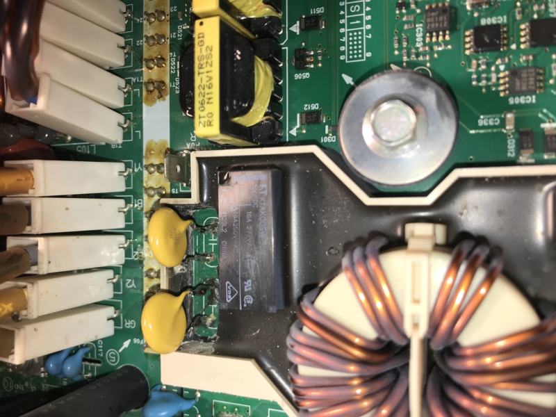
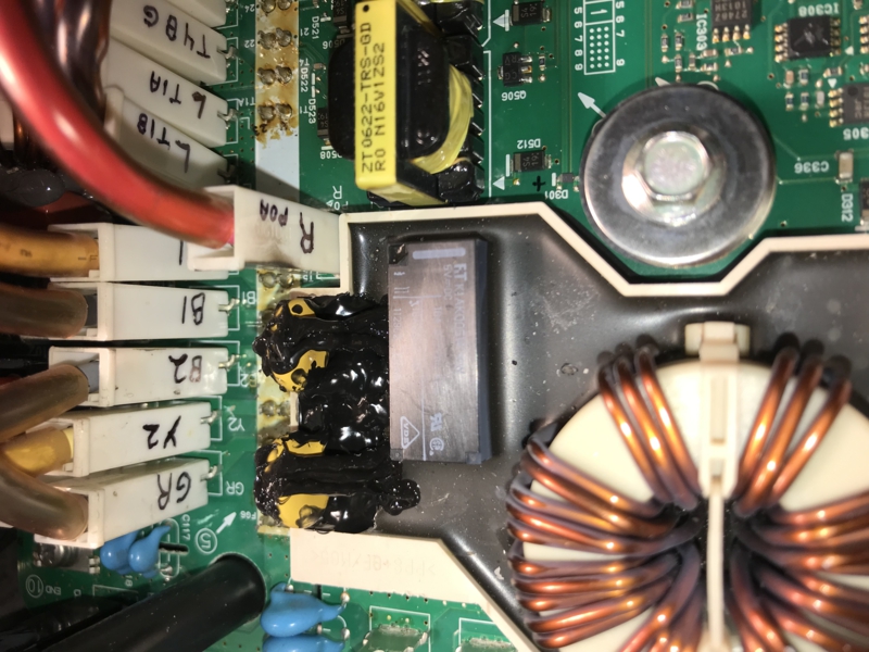
So far, I have changed the two snubber capacitor in the dog house.
IMG_2477_800x600.jpg


I measured 11 Ohms between the "N" and the "white wire connector"

I tested the relay and it bring the resistance to 0 Ohms when activated.

Cleaned the residue from the old blown capacitor.

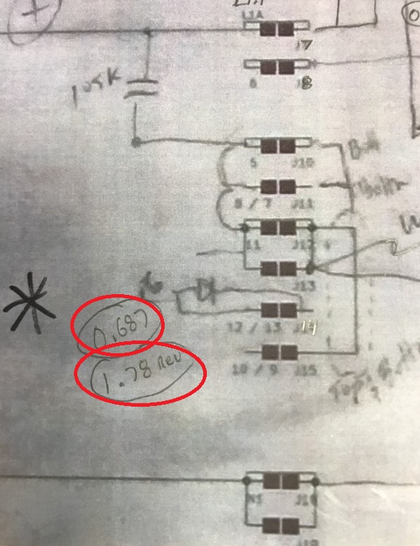
I measured the Wafle plate diodes value and all look good except this one here that had no value on the picture
I read 0.68 in one direction and 1.78 in the other direction.
IMG_2488_800x600.jpg


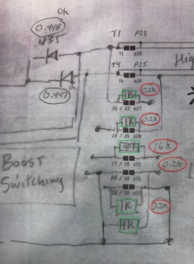
Resistances value were also different from the one noted:
( 0.2KOhms instead of 1KOhms )
IMG_2489_450x600.jpg


I tested related relays and fuses, everything is ok.

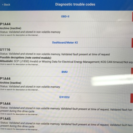
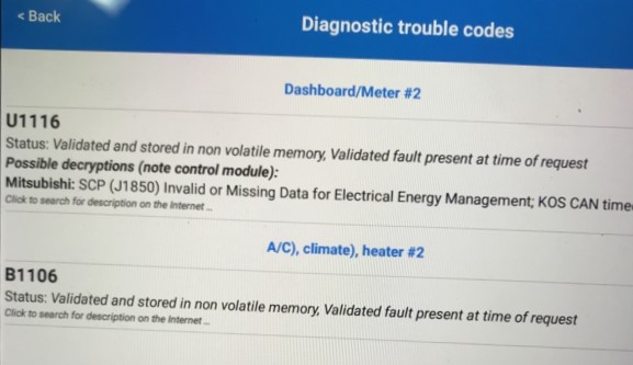
I have the following error codes from the OBD2:
P1A44
U1116
P1A45 ( Not always present after a reset though )
IMG_2487_OBC%20reconnected_800x600.jpg


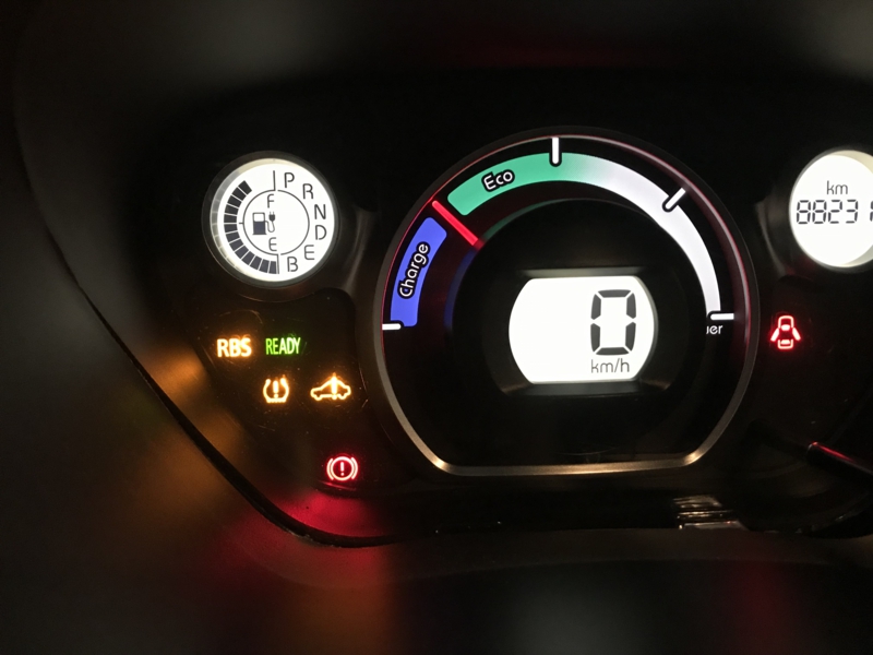
The car got the initial issue while driving ( B mode, aka max regen )

Now, I cannot charge the battery. It does the click, we hear the fan and a few second later everything stop.

When I start the car, if I quickly put it in drive or reverse, before the error show up on the dash, the car can move:
IMG_2490_800x600.jpg

I have access to the cabin heater, it also charge the 12 V battery to 14,5V.
When I put it on Park, cabin heater and 12 V battery charging both stop.
Trying to drive the car, it goes in turtle mode and limit the power and speed to 15km/h. ( 10 mp/h )

Strangely, I had access to the air conditioning yesterday ( before changing the capacitors ), but now, the compressor no longer start, making this noise :
https://youtu.be/T8RL_1gW4qk

I tested the cells with the CaniOn app and they are all perfectly balanced.

I am not sure what to do next.
 
The snubber repair looks good; i used some liquid electrical tape product from home depot to fill in the space and cover the exposed terminals, but most any RTV made for electrical applications would work (non-acid cure type).

re: waffle plate
Sorry for the poor quality of the drawing, the diode was marked as ".6" and your measurement was good.
On the 0.2k resistance, did you have the Faston tabs to the transformers connected or not?
There is a nicer drawing of what is inside the waffle and the faston wiring on page 1,
https://myimiev.com/forum/viewtopic.php?p=36349#p36349


P1A44/45/46 DTCs
These codes are indicating an issue with the HV Ground Fault Leakage Detection Circuit located inside the pack and communicates thru the BMU under the rear seat; there may be some other threads which investigate these codes, seems like the PTC Heater or the A/C Compressor are a likely source of this. A test might be to disconnect those 2 HV connections, 1 at a time, to see if the code clears. Also check all the connections to the BMU and pack for corrosion, bad wiring (rodent damage), etc. These codes will prevent charging or driving, so no need to try those until you can get these DTCs cleared.
P1A44 FSM troubleshooting

TSB correction for P1A46
P1A46(45) Mits TSB
 
Thanks a lot for your time and advice :)

I used liquid tape to fill the dog house gap. This material is way harder once cured compare to the original potting though. If they break again, it might be difficult to rework, so a softer silicone might be preferable.
Not pretty but it's done :
IMG_2515_800x600.jpg


re: waffle plate
All Faston tabs were disconnected when I took the resistances measurements.

re: P1A44/45/46 DTCs
Correct, once the AC connector was removed, those DTC error disappeared.
Brendon had the same issue and posted this helpful procedure to correct this issue:
https://forums.aeva.asn.au/viewtopic.php?f=49&t=7051&p=85898

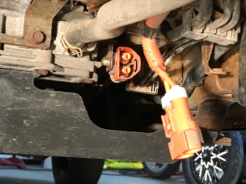
There is so much rust on my 10 years old I-Miev, I don't see how I will be able to remove the air conditioning.
Right now, I think I will try to find a pair of HV connectors, cap both and give up the AC.
(Under the car, front part of the main battery)
IMG_2516_800x600.jpg


Now, with the AC connector disconnected, I only have those two DTC error, but the car charge again from a level 2 charger.
IMG_2507%20AC%20disconnected%20with%20AC%20fuse_800x600.jpg
 
There are a bunch of threads on HV leakage in the AC compressor causing shutdowns

TL;DR: the lid to the electronics section of the compressor allows some water in.
You can solve the issue by opening, dewatering and then resealing

This can be done without disconnecting the compressor lines from the car, but you need to wrangle it a bit to get access
 
I was not successful at drying the AC compressor.

Once the AC is disconnected ( 350V connector under the car ), I can now charge and drive the car again!

Thanks you guys for your help on this matter, this is greatly appreciated.
 
Here's my story.
Car stopped charging, but DCDC was fine charging to 14.4v
Opened up the OBC and found blown 4.7ohm resistors (both) and melted 2.2mF 310v capacitor next to the resistors.
Snubber capacitors are ok, 20amp fuse in inverter is fine too.
Replaced the 4.7ohm resistors with the same value 9W resistors and 2.2mF 310v capacitor with a 2.2mF 400v one (closest I could find).
Everything back together and now it does charge... But not for very long ... or for very long. Everytime I plug it it charges for a different amount of time. And it doesn't officially stop the charging. EVSE says its charging, and car thinks it's charging(lamps on dash ok), keeps cycling the coolant pump etc. But reading it with a diagnostic tool (live data) I can see it stop charging.
Tried with another EVSE, with different current setting and a current display which also clearly shows it stopping the charge. Charging can stop anywhere between a minute or 15 minutes after plugging. Sometimes it doesn't stop at all and keeps charging to full.
Certainly looks like a cold solder joint ot bad contacts in the OBC, but where?
Could it be the snubbers starting to fail, or one or more of the 3 large capacitors?
 
It sounds like you had a failure on the AC Input side of the OBC. The bypass resistors blew because the AC relay did not engage; maybe the relay is damaged or the 12V battery was weak or there was a fault on the upper control board or etc... You would need to read the DTC codes to determine the fault.

Sometimes the charging halts temporarily for 20-30 minutes early in a session, not sure why but something in the controller does this, then starts back up again automatically. That may be what you are seeing.
 
Thank you for these amazing replies.
I believe my next step is to see if the dealer will replace the OBC.
I tested to see if charge was coming through a clip just ahead of the OBC and there was. Then I checked to see if there was any voltage coming to the orange wires coming out of the OBC into the inverter and there wasn't. Seems to be OBC to me.
As for the dongle question, I guess I don't know what a dongle is. I assumed it was the j1772 charger itself (?) which is the Mitsubishi supplied 110V one.

Thanks everyone and I'll keep you posted.
 
i find that using an internet web search can answer numerous questions about things i don't know,

https://duckduckgo.com/?q=OBDII+dongle&t=osx&iax=images&ia=images

Here's one i like and use to read the DTC trouble codes stored in the car's memory, using an android phone,

http://www.scantool.net/scan-tools/smart-phone/obdlink-lx.html

There are also scan tools that have cables and plug in to the OBDII port to scan and read the codes and data.
 
Hi!
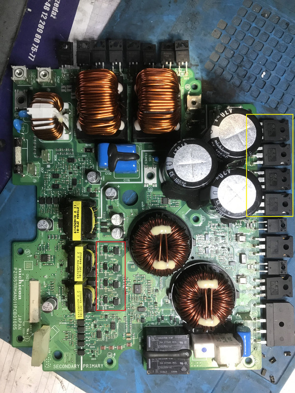
I'm trying to fix OBC 2013+ but I dont have diagram. I have problem with some connections:

OBC1.jpg


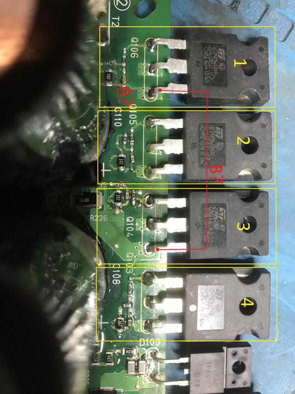
OBC2.jpg


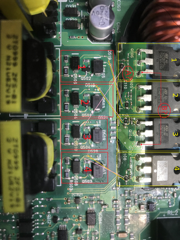
OBC3.jpg


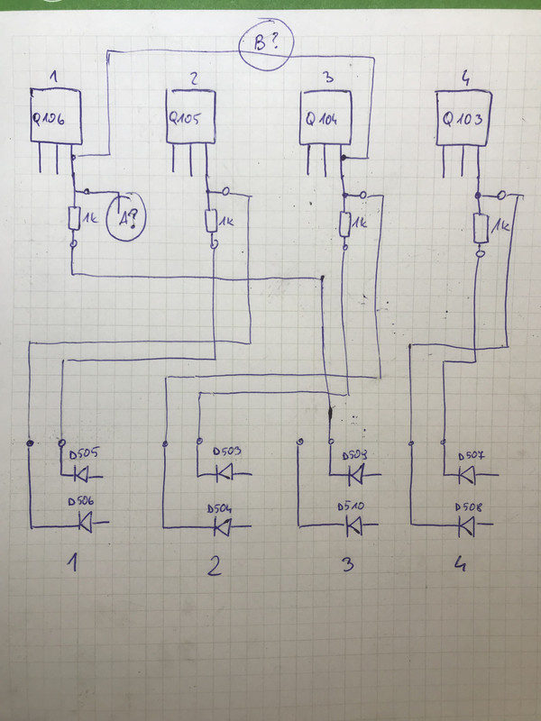
OBC4.jpg


I don't know where connect red"A" from the picture. I thinhk that it should be connected with D510 from red block 3 but it isn't, Maby connection is burned?

Next question is about red "B" connection. Yellow Mosfet no.1 from the picture is connected with Yellow mosfet no.3. Is it correct? Mosfet no.2 isnt connected with mosfet no.4....
 
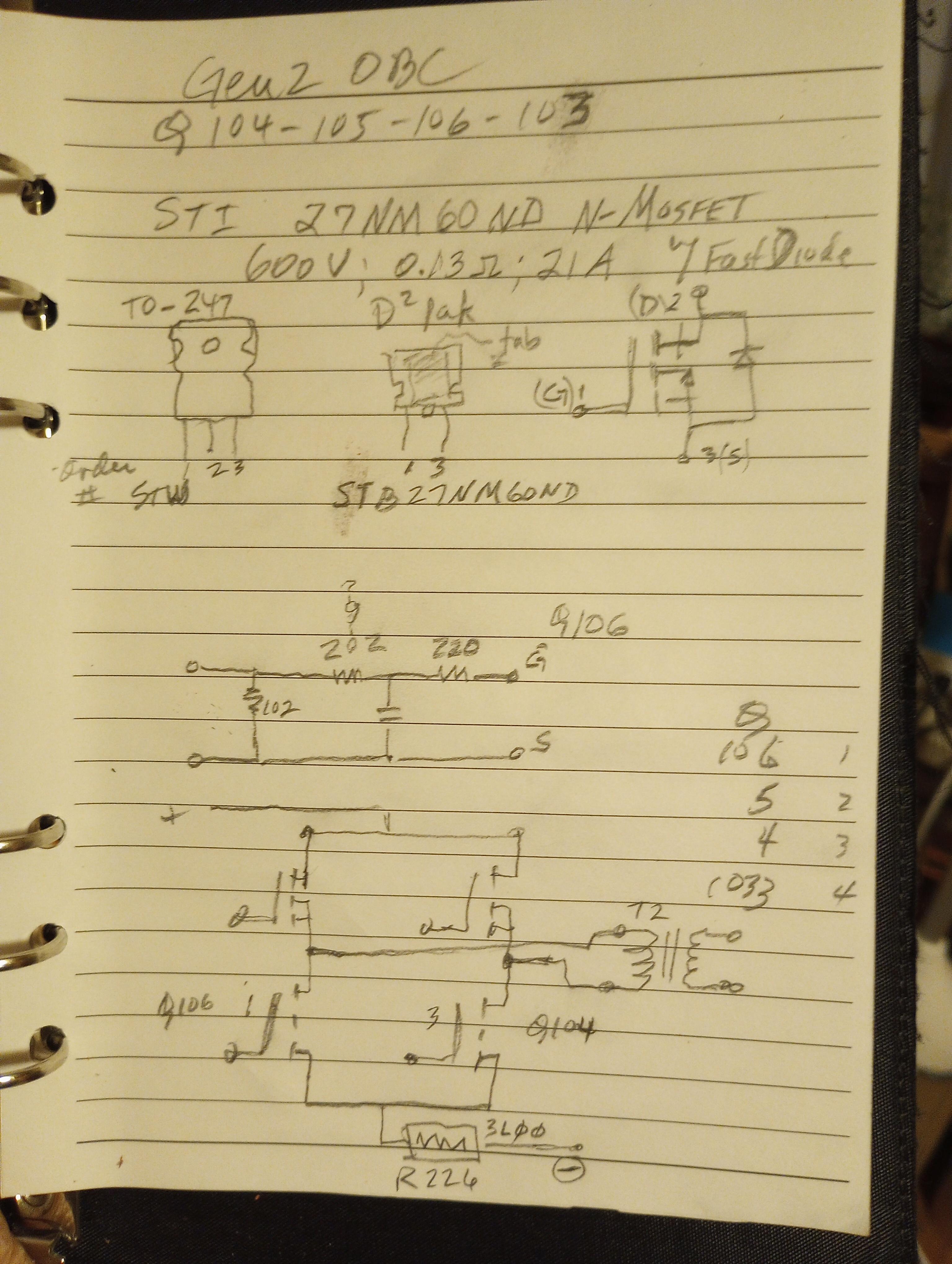
Did you desolder some of the mosfets, e.g. Q103-104-105-106 ? It looks like solder is missing

Those 4 fets make up an H-bridge that is switching the DC thru that big transformer in the FR corner of the OBC.

aGcsuZA.jpg
 
I desolder it for measuring time. All 4 fets was damaged, so there are new.

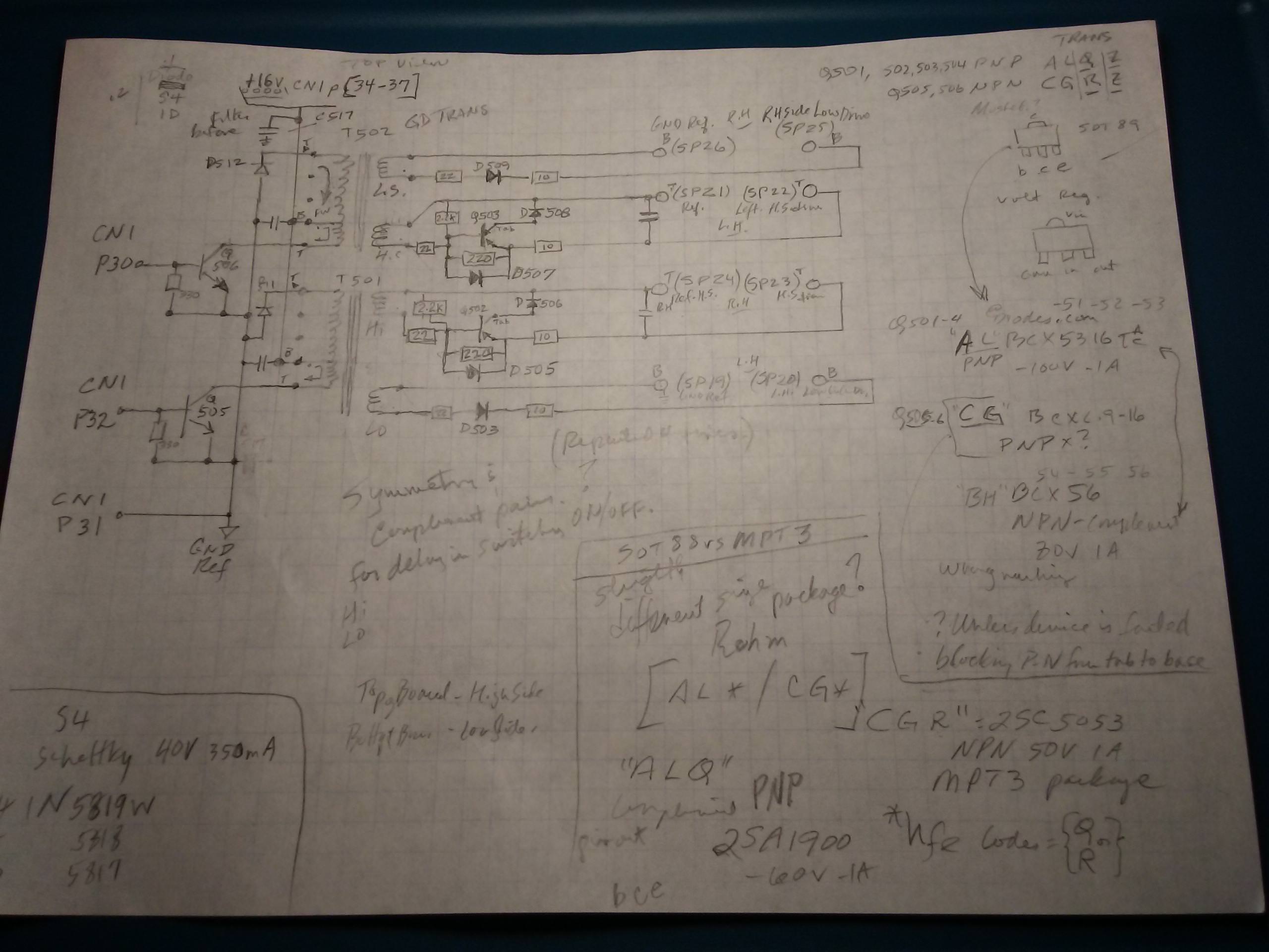
Thanks for diagram! Do you how these fets are control by?

I think that:
Q501 controls Q104
Q502 controls Q105
Q503 controls Q103
Q504 controls Q106

Am I right?
 
Yes the FETs are controlled in pairs (cross pairs of the H-bridge) so only the upper on one side and the lower on the other side are ON at the same time. This is done by control of the Gate Drive transformers.

Measure for continuity between the Source and the Drain of the neighbor FETs to fill in the layout of my diagram, (i'm guessing that Q105 and 106 will be the top and bottom on the same side of the H)

The trace from under D510 does appear to be a different color--was the green solder mask removed or burnt off?

With all 4 FETs blown then there is something else damaged or at fault that needs to be found.

Go take a look at the thread about these OBC2, you may want to post there to keep it all together,
https://myimiev.com/forum/viewtopic.php?p=44637#p44637
 
kiev said:
i started a sketch to figure out how the signals are sent to the waffle plate.

EH2A3z6.jpg

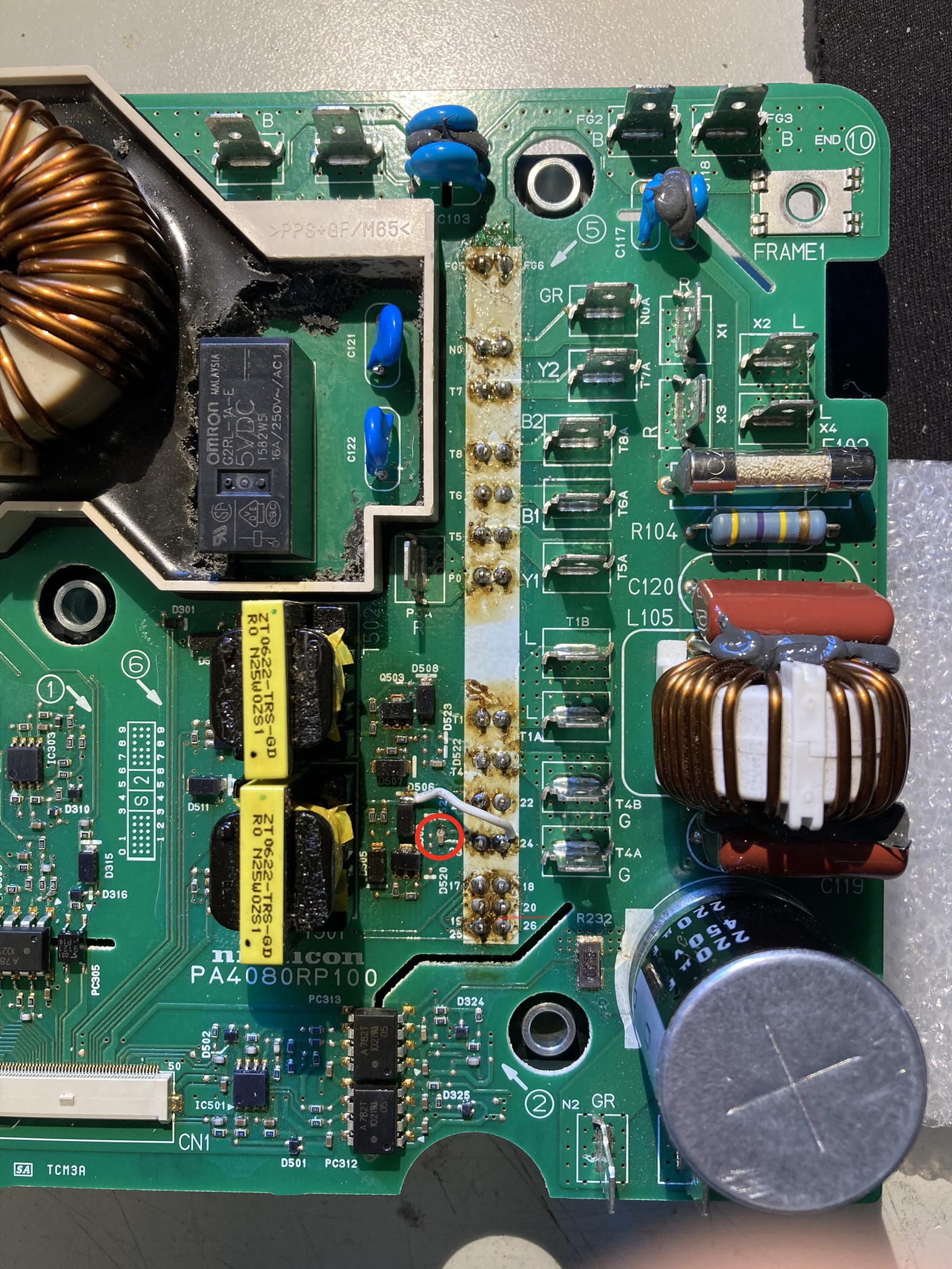
I am trying to repair my 2011 OBC with blown 4.7 ohms resisters (replaced relay, AC filter and snubber caps also).
During repair I damaged a the small capacitor, that's connected between pins 23/24 of the right waffle plate connector. I think, it's the very same, kiev has drawn in his sketch, with no further annotations to it.

Ua36UIU.jpeg


I would say, it's a filter for high frequency noise, not sure if it's really necessary.

Has anyone an idea, what size that capacitor has? The are no markings on it.
I would maybe replace it with a through hole type soldered over pin 23 and 24.

The white wire I added is repair due to some unsoldering damage.

Your help is much appreciated!
Hayo
 
@ Hayo,
You should give thanks to Jay for the failed OBC used for all of these circuit tracings.

i removed the 10 Ohm resistor to open up the path thru the transformer and measured 10 nF across that capacitor using Smart Tweezers at 10kHz.

On another OBC from Joe with the waffle plate and everything intact, then i was getting intermittent readings on those capacitors for both the 21-22 and 23-24 pairs of solder junctions. (e.g. zero to 4.5 to 6.5 pF readings)

If you try to measure those two capacitors in-circuit, then the resistance of the loop thru the transformer will overwhelm the reading, R ~250 Ohms shorts out the capacitance reading.

Good luck to you, hope the repair goes well.
 
Привет всем ... мой OBC GEN 2 перестал заряжаться, выдал следующую ошибку P1D10 Output Current (Control Fail). Можете что-нибудь посоветовать?
 
OBC NEWS
My last successful OBC repair (4.7 ohm resistors + snubber) is documented in this thread.
Last posts on page 84. https://myimiev.com/forum/viewtopic.php?t=4079&start=830
From Sa 18.12.2021, my I-MIEV 2011 was charged without any problems until last week.
Now 4.7 ohm resistor broken again (but looks like new)
Before I mounted the OBC cover after the last OBC repair, I checked the heating of the 4.7 ohm resistors
during the normal charging start. Temperature rise only approx. 3 K.
Newly identified problem, for the failure of the 4.7 ohm resistors, is the relay coil connection on relay RL1.
My currently defective OBC:
Measurement at the freewheeling diode D301, (with resistance range !) infinite resistance (normal approx. 59 ohms).
Lightly pressing the relay on the coil side, then suddenly 59 ohms. Bad solder joint.
The problem was discovered by the German "I-MIEV repair Pope" elektrozitrone from the forum:
https://www.goingelectric.de/forum
He's already fixed a few triplets with the same problem.
My current status:
Removed only upper circuit board. Defective relay surgically stripped. Save the PINs on the surface !
New parts coming this week. I will report with photos.
siggs
Slava Ukraini
 
Back
Top