The Troubleshooting and Repair for On-board Charger (OBC) Thread

Mitsubishi i-MiEV Forum

Help Support Mitsubishi i-MiEV Forum:

This site may earn a commission from merchant affiliate links, including eBay, Amazon, and others.
OK, I went on with testing the ICs out of the category “others”:
Others:
74VHC123A, Multivibrator, IC#: 505,706 Vcc pin16
ST95320W, eeprom, IC#: 508 Vcc pin8
TJA1050, CAN Transceiver, IC#: 704 Vcc pin3
JRC2746, Dual OpAmp, IC#: 515 Vcc pin8

After having disconnected all these ICs I’m now reading a resistance of 774 Ω from 5V to Ground and of 674 Ω when switching the leads.
The resistance ranking of the ICs so far is (in ascending order):
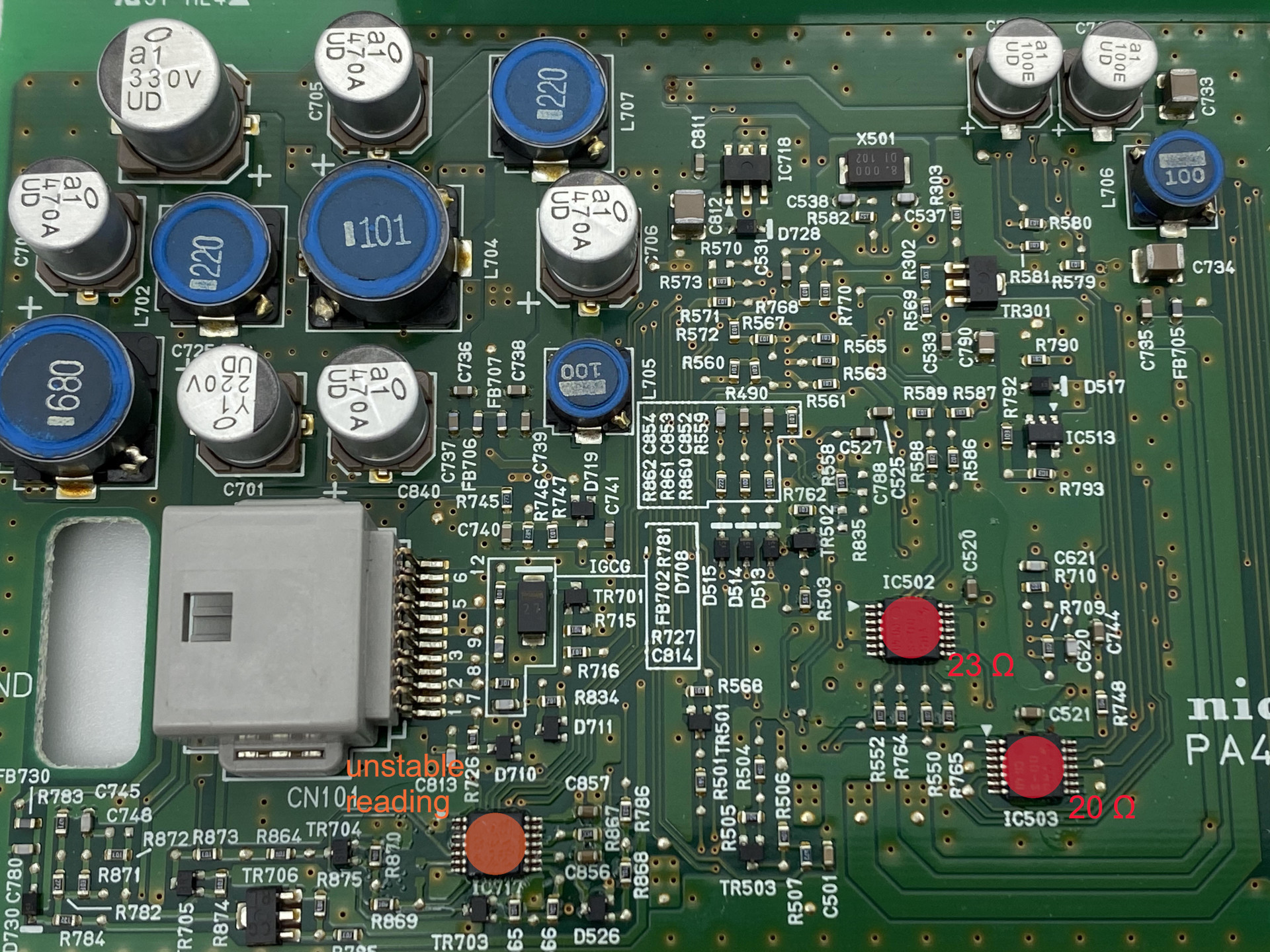
IC503: 20 Ω
IC502: 23 Ω
IC506: 33 Ω
IC518: 52 Ω
IC504: 56 Ω
IC704: 62 Ω
IC505: 91 Ω
IC716: 356 Ω
IC508: 735 Ω
IC706: 66.5 kΩ (or 60 kΩ when switching the leads)
IC515: OL (or 20 MΩ when switching the leads)
IC705 and IC717 are particular: they show a strange behaviour as reading won’t get stable: during minutes, measured resistance will grow by 1-3 unit steps of the smallest digit displayed (1-3 Ω when meter display is showing kΩs, 1-3 kΩ when meter diplay is showing MΩs). I stopped the measurement on IC705 after several minutes of watching the figure go up from around 1 MΩ to 2.3 MΩ (and from around 240 kΩ to 760 kΩ after having switched the leads) although the figures hadn’t settled. The growing reading is to observe independently of the sense of the measurement (leads switched or not) and on all reproduced measurements. The same is for IC717: no stable reading came out, resistance was at least 240 kΩ before starting growing. So, these chips won’t have participated to the short, but they are doing strange things. You may be surprised that these findings are not in line with what I had written in my last post: I realized when measuring today that on the measures taken last time, I had contact to the 5V circuit (my lead was touching the disconnected VCC contact of the IC but also the solder pad of the 5V supply from which it had been disconnected). The around 60 kΩ of resistance I had measured were between the 5V solder pad and Ground. I’m finding these same resistance values also when I’m touching with the leads the capacitors next to the VCC pins of IC717 (C857) or of IC705 (C818) and measure against Ground.

And the same information as readings included into the pictures:
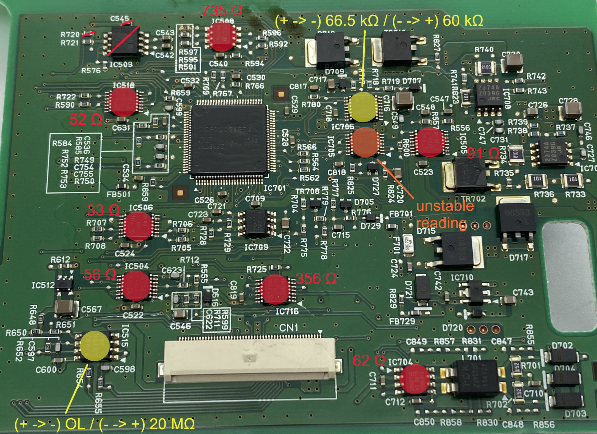
vTtRIeJ.jpg


qUIrcVU.jpg


I don’t want to be too optimistic, and some expert opinion will be very welcome to interpret these findings. The resistance values from 5V to Ground (and vice versa) are now higher than those that Kenny had measured on his boards. To me, this looks as if the devices creating the short have now been disconnected and the board could have not too bad chances to work correctly again if the devices having a resistance of less than 1kΩ (IC503-IC508 according to the order of the list above) would be replaced. I don’t know at all what I should think about IC705 and IC717. I don’t know if the observations made on them are part of a normal behaviour, if it’s a sign of damage of the ICs or if it could be a sign of even more trouble somewhere in the circuit around these two ICs.

This is too much of an open end for me so @kiev I’ll contact you via PM concerning the board you have. Would be great if this could be the solution!
 
i don't have any loose parts to check for comparison, but i might just order up a batch to have on hand for this sort of thing and to do repairs.

The goofiness of the 2 out of 3 Hex inverters, 74VHC14, may be due to internal circuits of the chip when it is not damaged. The meter response seems like it is charging up a capacitor somewhere.

The parts cost would not be high, and you could take it to an electronics repair shop that can do surface mount soldering to replace the chips.

Probably the 12V to 5V power supply should be checked before going too far down the repair path, but it is definitely looking hopeful.
 
kiev said:
The meter response seems like it is charging up a capacitor somewhere.
Agreed. Those are possibly op-amps or similar with dual power supplies (e.g. ±5 V); a low resistance from +5 V to -5 V supply pins would cause the meter to be reading the capacitor on the -5 V rail. For those, it's best to lift the two leads for power supplies, and test from one lifted lead to the other instead of the one lifted lead and ground.
 
Thanks for your interpretations of my findings. I had another look into the datasheet of 74VHC14FT (the goofy IC705 and IC717) to determine another pin to desolder. The device is described as being a Hex Schmitt Inverter.
Besides the VCC and Ground pins there are only 6 logic IN and 6 logic OUT pins on the device. There isn't anything really looking like a second power supply... Another idea how to troubleshoot these ICs?

How would you proceed to test the ICs out of the "power supply ICs" group? That would be the last ones out of Kenny's list that still remain to be tested...
Power Supply ICs would use a different technique to troubleshoot
JRC2374, PWM DC/DC Regulator, IC#: 707, 708
MO33, 3.3 supply chip, IC 718
TACQ, Voltage regulator chip, IC513
 
The goofiness is all mine. I didn't realise that you'd already determined these to be hex Schmidt inverters. So definitely not dual supply op-amps. Sigh.

Sorry for the bad steer.

Edit: as for testing, they are inverters, so a low voltage at an input should translate to a high (very nearly equal to the pin 14 power supply) at the output. Similarly a high input should produce a low output. Medium voltages (between roughly one third and two thirds of Vcc) will end up high or low, but should be stable, because of the Schmidt trigger hysteresis.

To test one, solder bridge its Vcc to the board again and power with 3.5V or so (maybe 5V now that most of the short circuit is gone). That might give you the confidence to assume for now that they don't need replacing.
 
For the Hex inverters, now lift the ground pin and then check the resistance from the Vcc to ground pin.

It is possible that now you are seeing the variations due to contribution from capacitors. Before you removed the shorted parts, the low resistance of the short dominated the readings. That's just my guess to explain the meter readings.

Now that all the shorts are disconnected, retry your 2 to 5 volt testing and if possible measure your current--it should be much lower than before and nothing should be heating up. Also check the microcontroller ic701 for heating when you do this.

To check the power supply ics you will need to apply 12 V power and ground to the appropriate pins of the CN101 connector. Pin 12 is the switched 12V supply, and i measured about 30k Ohms from + to -, and when reversed. There is definitely some charging up of capacitors by the meter so it may not settle down. But if your board is not somewhat similar then don't apply power.

When you do apply power you will want to limit the current of the 12V to about 50 to 100mA. After the 12V has been connected then you can check the 5V supply to ground to see if it is being created, and if it is then check the 16V supply to ground.
 
During the weekend I did the tests you had suggested, to find out more about the health of the 3 hex inverters ICs and the power supply ICs creating the 5V and 16V power supply.

The test based on verifying the (inverting) reaction of the inverter ICs didn’t bring satisfying results. I supplied the 5V directly to the ICs Vcc leg, maybe I should have solder bridged it again, but I saw no good reason, why it should have changed the test result. These IC legs are so small and they are so close to each other and input and output of one circuit are always direct neighbours... Not to forget the varnish or glue that covers great parts of the board, including the IC legs, so you never know if you have good contact to your measuring object or not. I didn’t manage it well to contact the leads to supply the input to one and get the outgoing signal from the other, reading the meter at the same time. I haven’t been able to observe the behaviour I should have observed for these ICs, but as mentioned, this may also be due to my testing “technique”. My impression was that they didn’t work as they should.

I went on and desoldered the Ground leg of each of the 3 ICs. There the results are easier to interpret: I measured the following resistances from Vcc to Ground through the ICs:
IC705: 102 Ω
IC716: 249 Ω
IC717: OL
This time the values settled quickly, there was no effect of loading capacitors to observe.

The resistance values between 5V and Ground (and vice versa) haven’t been changed much by the desoldering of these 3 contacts:
5V -> Ground: 760 Ω (was 774 Ω before)
Ground -> 5V: 630 Ω (was 674 Ω before)

When supplying 5V to the 5V circuit, there is no element heating up particularly. The board as a whole gets a bit warmer, but there is no device standing out of the rest. With higher air temperature on the day of this test, compared to the days of the other temperature measurements I had done before, the measured temperatures this time stayed under 36°C, where they had been at over 40°C on the earlier tests. And this time I applied 5V, on the temperature test before it had been only 2.8 and 3.5 V.

Finally, I went on to the test of the power supply ICs and tried to create the 16V and 5V power supply out of the 12V power supply. I had verified before that the resistance from the 12V pin of IC101 to Ground was at around 30 kΩ. And yes, it was. The 16V is created. Voltage is even a bit higher, more around 16.5V. The 5V however is not created that nicely. There is definitively a stable voltage created, but it is of only 0.66V. I don’t know if the large number of disconnected ICs could be part of an explanation for this gap. The current pulled at the 12V didn’t get over 40mA.

So… that’s the news from my board. I just noticed that your last reply to me in this thread was your 1500th post, Kenny. Congratulations! Impressive figure!
 
Haha, thanks i hadn't even noticed the number of posts.

Indeed the "16V" supply is actually higher and closer to 17, but nominally i just refer to it as the 16. But that is a good test result to prove certain portions are okay and working.

The 16 gets created from a boost PWM regulator chip from the 5V supply, so even though you found the 5V was pulled low somewhere, it is held up elsewhere sufficiently for that task.

i would guess that there is still some component(s) pulling down the 5V, maybe not a direct short that can be measured by Resistance readings, but gets turned on and then completes the path, such as transistor, diode, or a secondary supply such as 3.3V created from the 5V. e.g. IC718; ic512, 513; TR301, 706;

i really wonder about IC512 due to its proximity to the 5V line damaged up at the primary site. It is marked "TACQ" and i think it is a TI TL431 part number, precision reference voltage chip.
 
kiev said:
i would guess that there is still some component(s) pulling down the 5V, maybe not a direct short that can be measured by Resistance readings, but gets turned on and then completes the path, such as transistor, ...
I would be more inclined at this point to think that something that was trying to supply 5 V into a near short circuit was damaged. The fact that you can run the 5 V circuit on actual 5 V now without excessive heating suggests that to me. So I'd look now at what generates that 5 V rail.

Edit: my guess is it's under the area of the board with all the inductors on it, beside the connector. I wonder if it's possible that one of the chips you disconnected from 5 V is needed to generate the 5 V rail? That sounds a bit silly as I type it. But maybe there is a check on the level of the 5 V rail, that you have disconnected, so now it thinks there is something really bad happening and is stopping the 5 V as a precaution.
 
coulomb said:
But maybe there is a check on the level of the 5 V rail, that you have disconnected, so now it thinks there is something really bad happening and is stopping the 5 V as a precaution.

i think you are on the right track here. When i was tracing the DCDC board there were several circuits with the function to check and compare that the low level supply voltages were present and neither too low nor too high; And on the lower power board of the OBC there are circuits which sense and feedback low level voltages to the upper control board. So it makes sense and i would expect that there are some supervisory circuits such as related to the presence of the Hot All The Time (HATT) and the Switched 12V and 5V supplies.
 
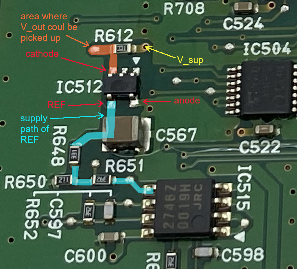
I had a close look at the datasheet of TI’s TL431/TL432 that could be the IC512 on the control board. Taking into account how the board’s leads are connected to the pins of the device, only the pin configuration of the TL431 DBV (SOT-23-5) package seems to fit (page 4 of the datasheet). I then skimmed through the test circuits (page 19 of the datasheet) and application and implementation examples (pages 22-30 of the datasheet) given in the datasheet. All examples have in common that they somehow value the information of the voltage at the device’s anode (referred to as V_KA or V_out) as output information from the device. In the case of the IC512 there is no connection going away from the anode other then the supply via the resistor R612 (300Ω, by the way). So, for me it looks like as if this valuable output information wouldn’t be picked up. And that makes no sense to me... Also, in the supply line of the REF pin, there is a voltage divider built by a 3.9kΩ and a 250Ω resistor (R651 & R 650). That would mean that a voltage far above 16V would need to be supplied by IC515 to get a 2.5V voltage at the reference pin of IC512. And 2.5V is the only voltage that is of any use at the reference pin of a TL431 as it is its internal reference voltage. The highest voltage I read about being available on the control board is 16V, so that would mean that in no situation a 2.5V could be supplied to the REF pin of the TL431. That doesn’t make sense neither... One of you has something that could give a sense to this configuration? Here's a marked picture to make things more clear:
ayBqePo.jpg


I also share your opinion that disconnecting so many devices must have an effect somewhere and that the inability to create the 5V rail could be one of those effects. What is hard to understand is why the 16V rail, that is created from the 5V, is created.
If we assume that the 5V rail would work if the other ICs would all be healthy and in place, next step would be to order replacement devices and do the repair, or do you see other anterior troubleshooting steps? Perhaps something concerning the ICs you had mentioned in an earlier post (IC718; IC512, IC513; TR301, TR706), Kenny?
 
iOnico said:
That would mean that a voltage far above 16V would need to be supplied by IC515 to get a 2.5V voltage at the reference pin of IC512. And 2.5V is the only voltage that is of any use at the reference pin of a TL431 as it is its internal reference voltage.
It might be a TLV431, which has a 1.24 V reference; see the datasheet . They have the same pinout.
 
iOnico said:
do you see other anterior troubleshooting steps?
Perhaps consider tracing more of the power supply circuit, so you can be confident of what is stopping the 5 V rail from coming up. And maybe start with replacing just that(those) IC(s).
 
i think that is a supervisory circuit for the 5V switched supply. V_sup in your diagram is the 5V Vcc supply and R612 limits the current into the ic512 marked "TACQ" and likely a TL431.

If the 5V is present then the 2.5V Vref is output thru the voltage divider 270/600 = 1.125V into pin 5 (non-inverting input) of the ic515 op amp, which is acting as a unity gain buffer. The output of the op amp on pin 7 is sent to the microcontroller pin 80. Without the firmware we don't know what it does with that signal, but it is my guess that it is used to sense the presence of the switched 5V supply.

i would be interested to see what voltage you read on the capacitors when you apply the 12V lines to the board, e.g. C703, 705, 706 and 840, if you can very carefully measure them. Normally would expect to see 5V on these.
 
Now I'm thinking that the cathode and Vref of the TL431 connect together, so the TLV is more or less a 2.45 V zener diode. It just clamps the max voltage at the op-amp to 1.1025 V. As long as the 5V supply is higher than 3.8 V, this will give about 1.1 V at the op-amp. So this may be a "power reasonable" signal (as opposed to "power good"). A lot of work to check something simple; I would just use 2 resistors. But there can be weird problems if a high voltage ends up at the analog input of a microcontroller, so that's maybe the reason. The op-amp might be to minimise noise as the signal is sent a long way?
 
Ok, having the IC512 acting as a zener diode, just like both of you are describing it, makes sense, even if I have to admit that I haven't completely understood how the IC does this. But that's certainly due to not being familiar enough with op-amps and their feedback loops. I'll probably have to read more into this.

I took the voltage measures on the capacitors with 12V being supplied via pin 12 of C101:
IC701: 17.4 V
IC702: 17.4 V
IC703: 5.16 V
IC705: 5.16 V
IC706: 5.16 V
IC840: 0.77 V

So all seem normal except of IC840. Its voltage corresponds more or less to the voltage observed on the 5V circuit that we're looking at since a couple of weeks. The values of the ICs 703, 705 and 706 seem to indicate that indeed a 5V is created from the 12V.
 
that is very promising to see that the 5V buss is being held up by the "700" series caps.

The circuits on the board seem to be sorted into "500", "700" and "800" series of reference designators, and i'm sure that is a clue to their function and purpose but don't yet have the key to break the code.

It may be that you need to apply 12V to the HATT time pin 7 of CN101 and pin 12 at the same time also and recheck the capacitor voltages. If no change then move on to the next to check the ferrite bead.

C840 seems to be connected to the 5V buss thru a small ferrite bead on the top side, FB706, which should read about 0.5 Ohms across it; if it is open circuit (blown like a fuse) then that is a possible reason for no 5V on C840. It also seems that the only consumer of 5V from C840 is IC505, a VHC123 Dual multivibrator chip on the bottom side. Vcc is pin 16 and there may be another connection to 5V at pin7, i don't recall if you removed pin 16 before.

It's also possible that C840 was damaged and internally shorted; if the FB is okay, then maybe you could carefully reach in with the soldering iron to the negative side, put some heat on that pad and rotate the cap up and over slightly to get one side of C840 removed from the board. With it removed check its resistance and also that of the 5V Vcc buss to ground for any changes.
 
kiev said:
that is very promising to see that the 5V buss is being held up by the "700" series caps.
Agreed.

It may be that you need to apply 12V to the HATT time pin 7 of CN101 and pin 12 at the same time also and recheck the capacitor voltages.
Yes! That seems likely to me.

If no change then move on to the next to check the ferrite bead.
I thought that the FBs must really be FusiBle resistors, rather than actual beads. But it seems that they can make them SMD somehow. It must be a sort of "coating" of ferrite around either a metal strap or a very low resistance resistor. Amazing what they can cram into an SMD these days.
 
It may be that you need to apply 12V to the HATT time pin 7 of CN101 and pin 12 at the same time also and recheck the capacitor voltages.
No change. voltage on IC840 remains at 0.77V.

I then measured resistance at FB706 and FB707 with the 12V being applied to pin 7 and 12 of CN101 (what I shouldn't have done: resistance measures are always to be taken without a voltage applied - end of edit). The meter showed 0.0Ω for FB706 and 0.5Ω for FB707. Before, I had tried to measure these resistances without a voltage applied, but the reading was just jumping around, probably due (once again) to loading capacitors.

It also seems that the only consumer of 5V from C840 is IC505, a VHC123 Dual multivibrator chip on the bottom side. Vcc is pin 16 and there may be another connection to 5V at pin7, i don't recall if you removed pin 16 before.
Pin 16 of IC505 is disconnected. Pin 7 is still connected.

I'll (try to) disconnect a lead of C840 next, or would you start with disconnecting pin 7 of IC505?
 
Back
Top