The Troubleshooting and Repair for On-board Charger (OBC) Thread

Mitsubishi i-MiEV Forum

Help Support Mitsubishi i-MiEV Forum:

This site may earn a commission from merchant affiliate links, including eBay, Amazon, and others.
Sorry i wasn't explicit about the test conditions, but you never attempt to measure resistance with a voltage applied to a circuit. This is common knowledge to those with experience in electrical repairs, but not to everyone on an internet forum. It should be understood that there is no voltage applied when trying to measure resistance, capacitance, continuity or diode voltage drops or transistor polarity. Only measure voltage when power is applied and be very careful what and where you touch the probes.

The cap voltage was one test with voltage applied; then turn all the 12V power off and make the resistance measurement.

A resistance reading of OL is an open circuit (infinite resistance = no continuity); 0.0 Ohms is a short circuit, and 0.5 is a very low resistance almost a short circuit. The FB parts are intended to act a short circuit jumpers across a gap in the traces and possibly blow open like a fuse in the event of an overcurrent condition in order to protect down stream components.

So with no power applied, is there continuity across FB706 or is there no continuity?
 
iOnico said:
I had tried to measure these resistances without a voltage applied, but the reading was just jumping around, probably due (once again) to loading capacitors.
Ah. But fuses (when good) are low resistance devices; they should not be affected by other circuit elements such as capacitors. If you were getting fluctuating readings, you're either not connecting to the fuses properly (e.g. due to a conformal coating, or oxide), or the fuse is open circuit (blown).
 
Ok, forget everything I have written about FB706 before. I don’t know what I did when I measured last time but obviously it was crap. I measured the resistance through FB706 again and the value takes only 2 seconds to settle to a stable value of 741Ω. So, FB706 is another damaged part and very likely the reason why the 5V supply is of only 0.77V on the 5V circuit we’re looking at since a couple of weeks.


Besides of this finding on the damaged control board (let’s call it “control board 1” in future posts), there has been the following development in parallel:

I had played the option of the possible repair “shortcut” and got a replacement control board from Kenny (for disambiguation, let’s call this board “control board 2” in future posts). Having put control board 2 into the OBC and put everything together again, the test if the charging process was working again ended in a disappointment. The charging still interrupts during its initialisation steps, just like I had described it at the end of this earlier post. I also did the test with two different flat ribbon cables, getting the same result. So, if we exclude the control board and the flat ribbon cable as potential error sources, remains the power board.
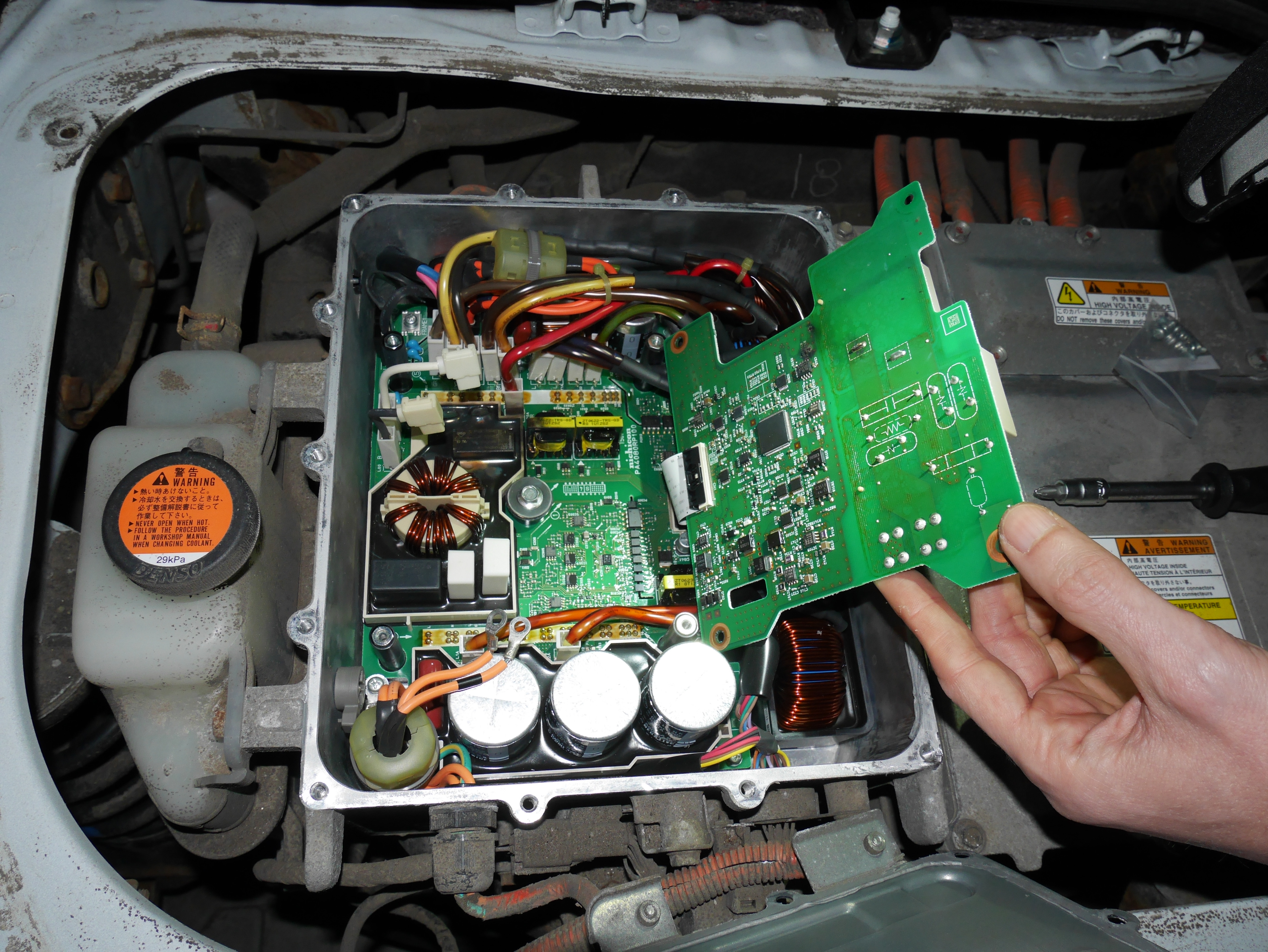
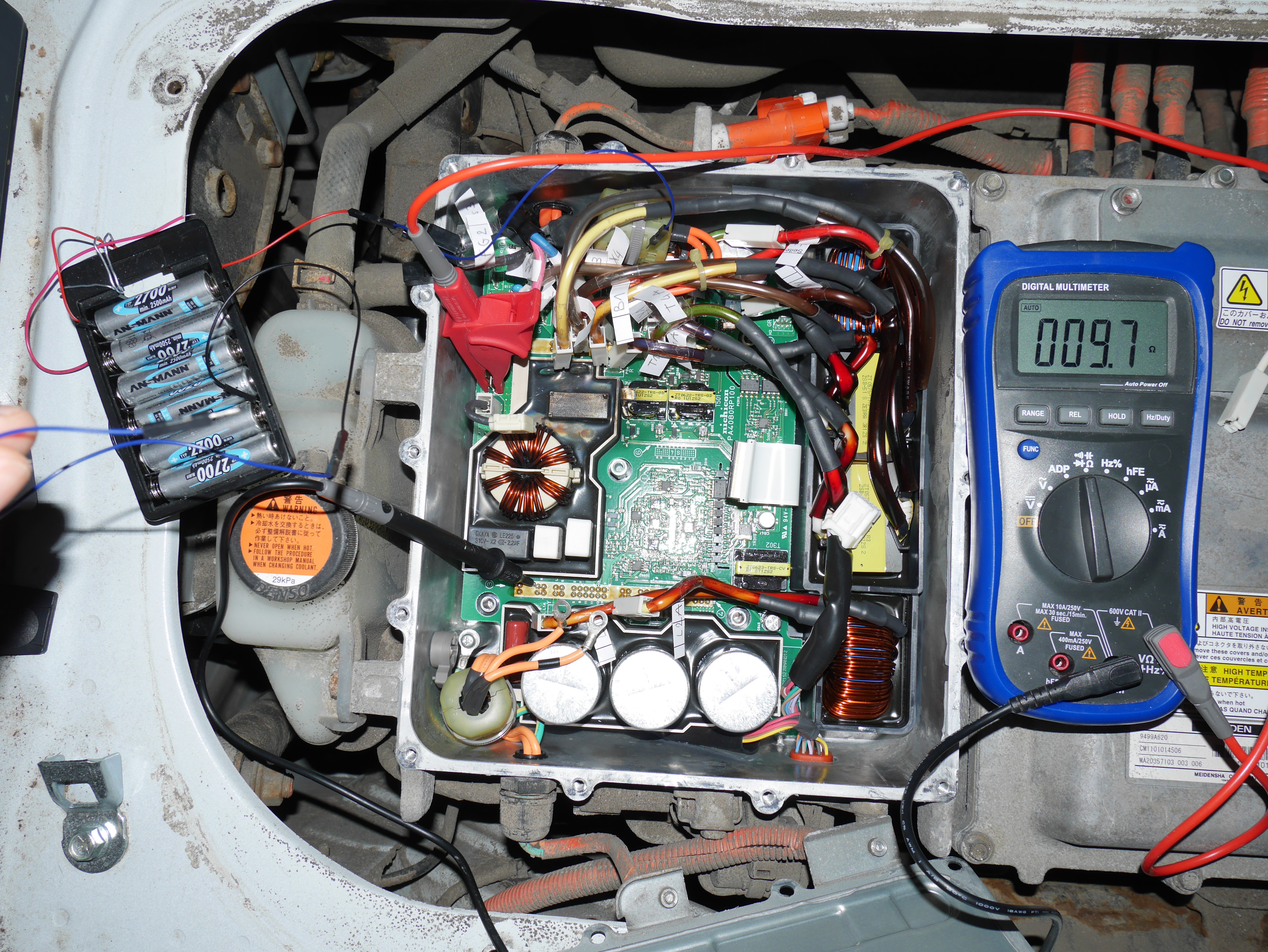
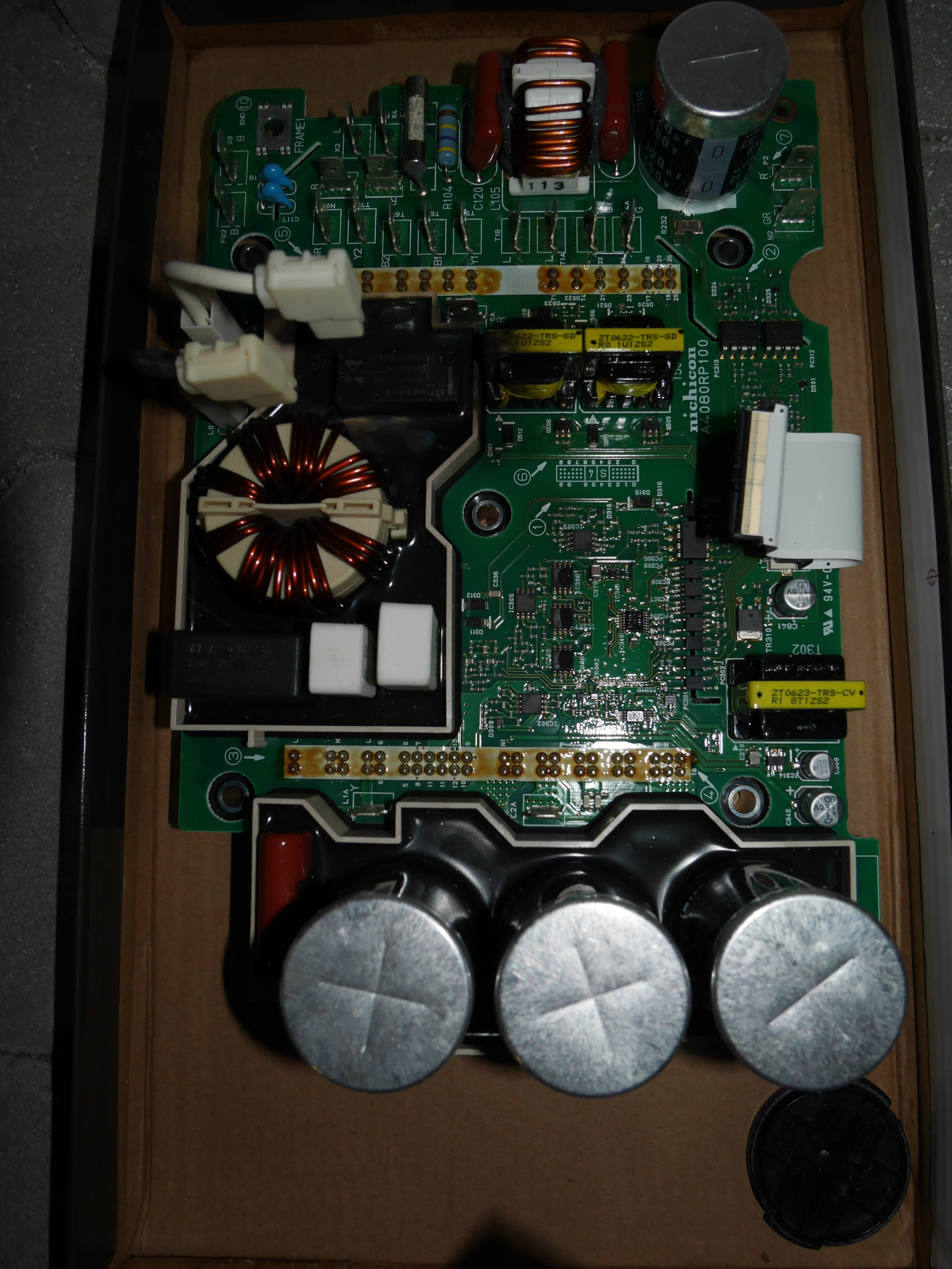
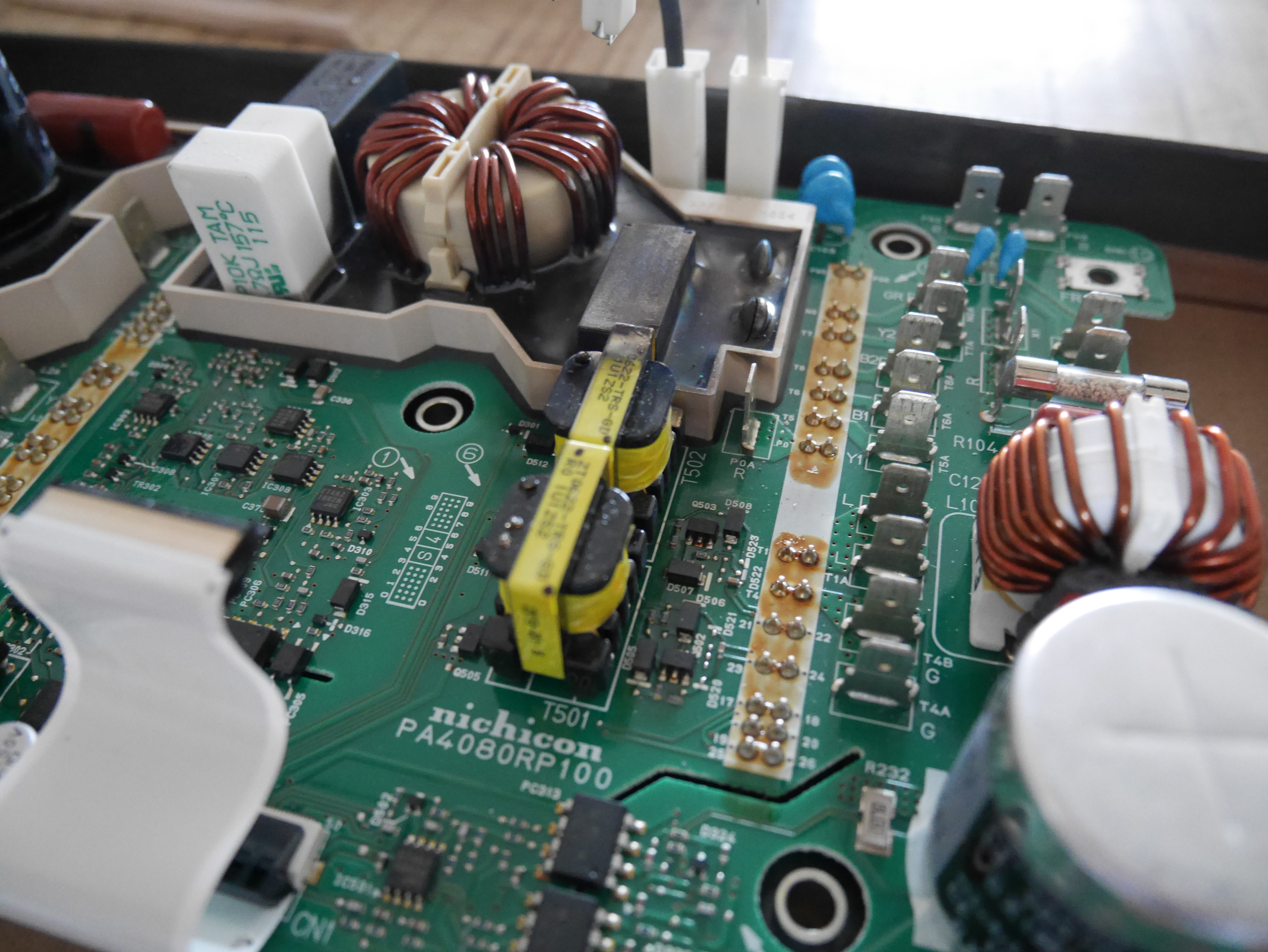
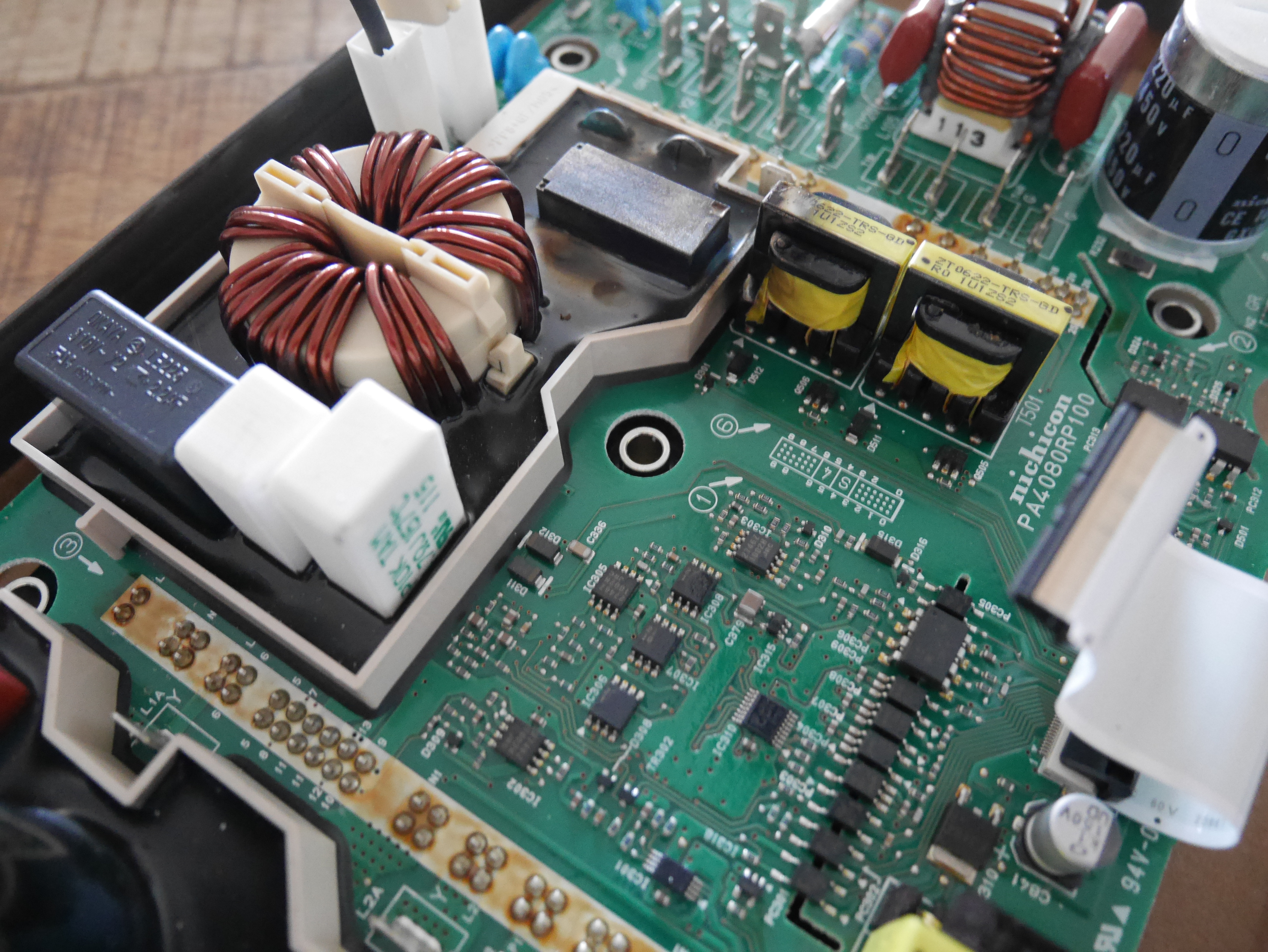
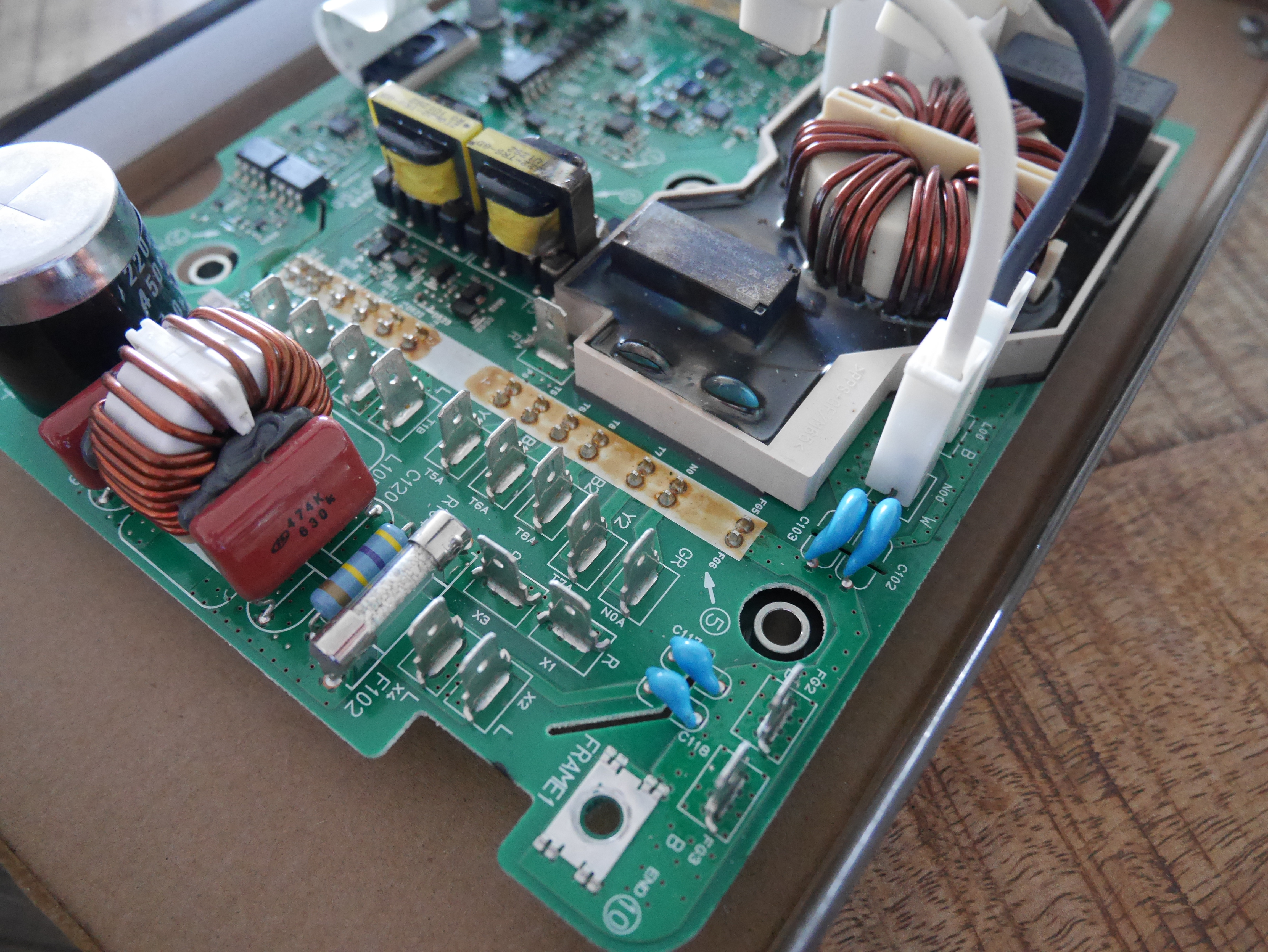
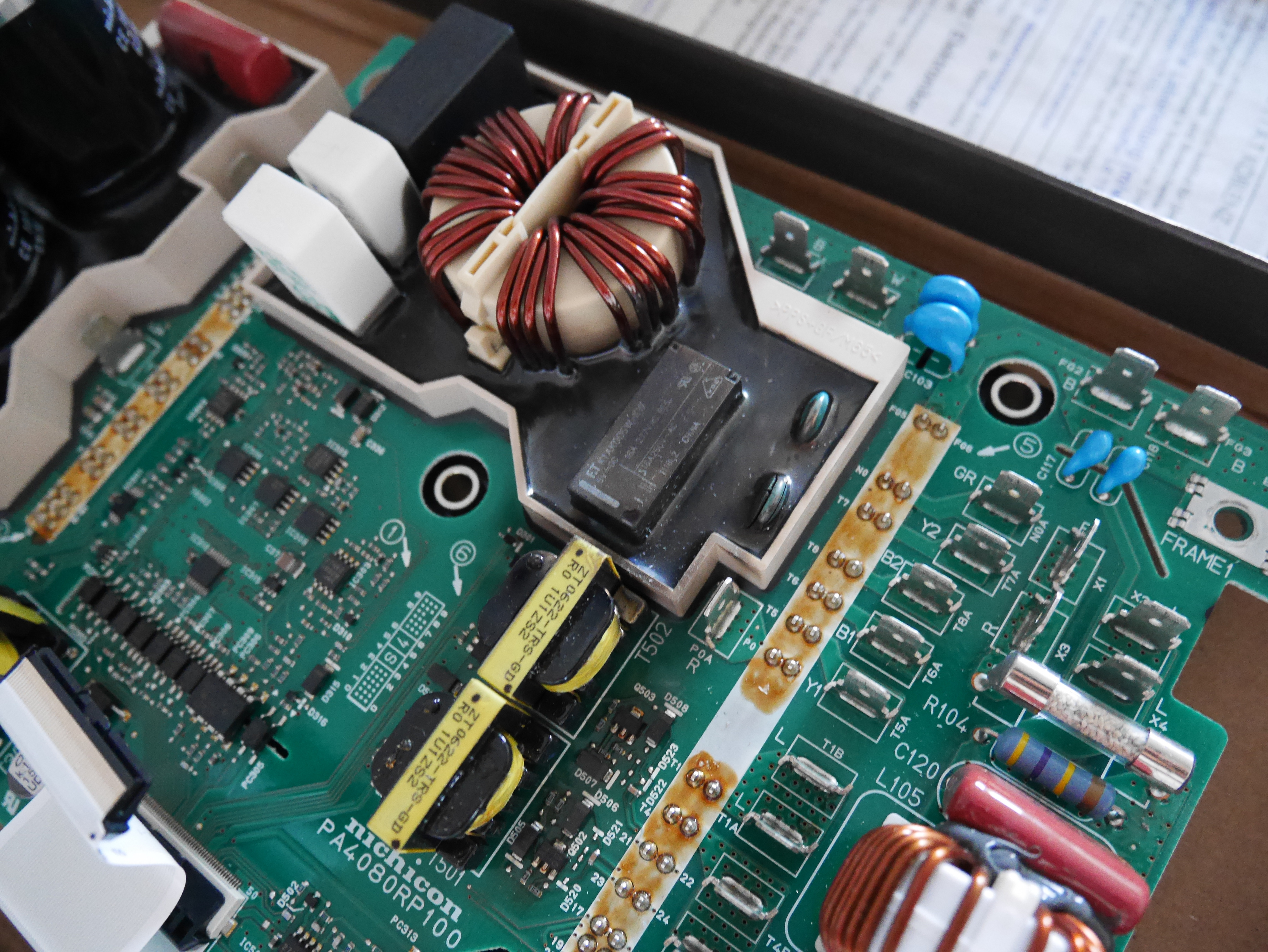
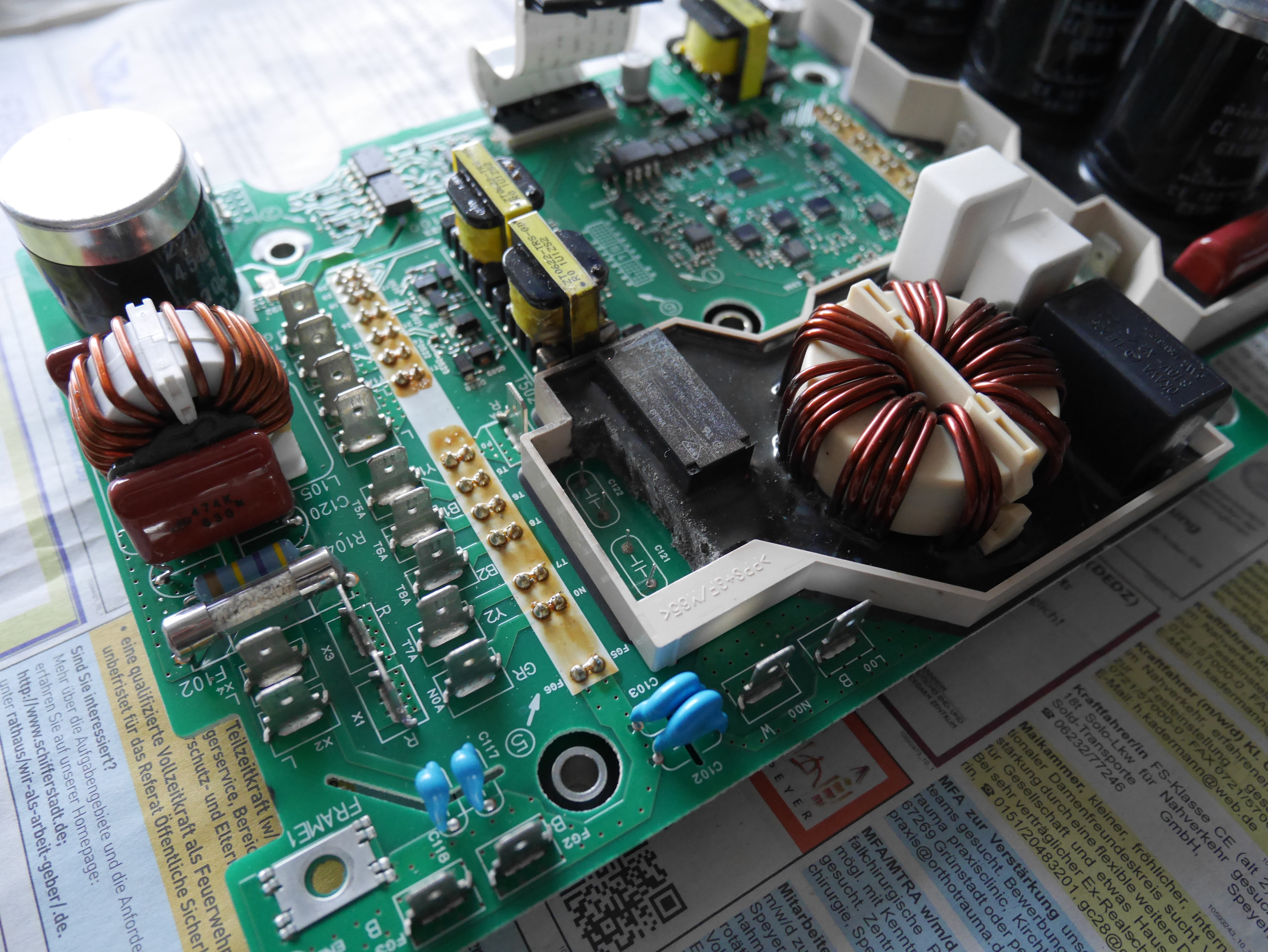
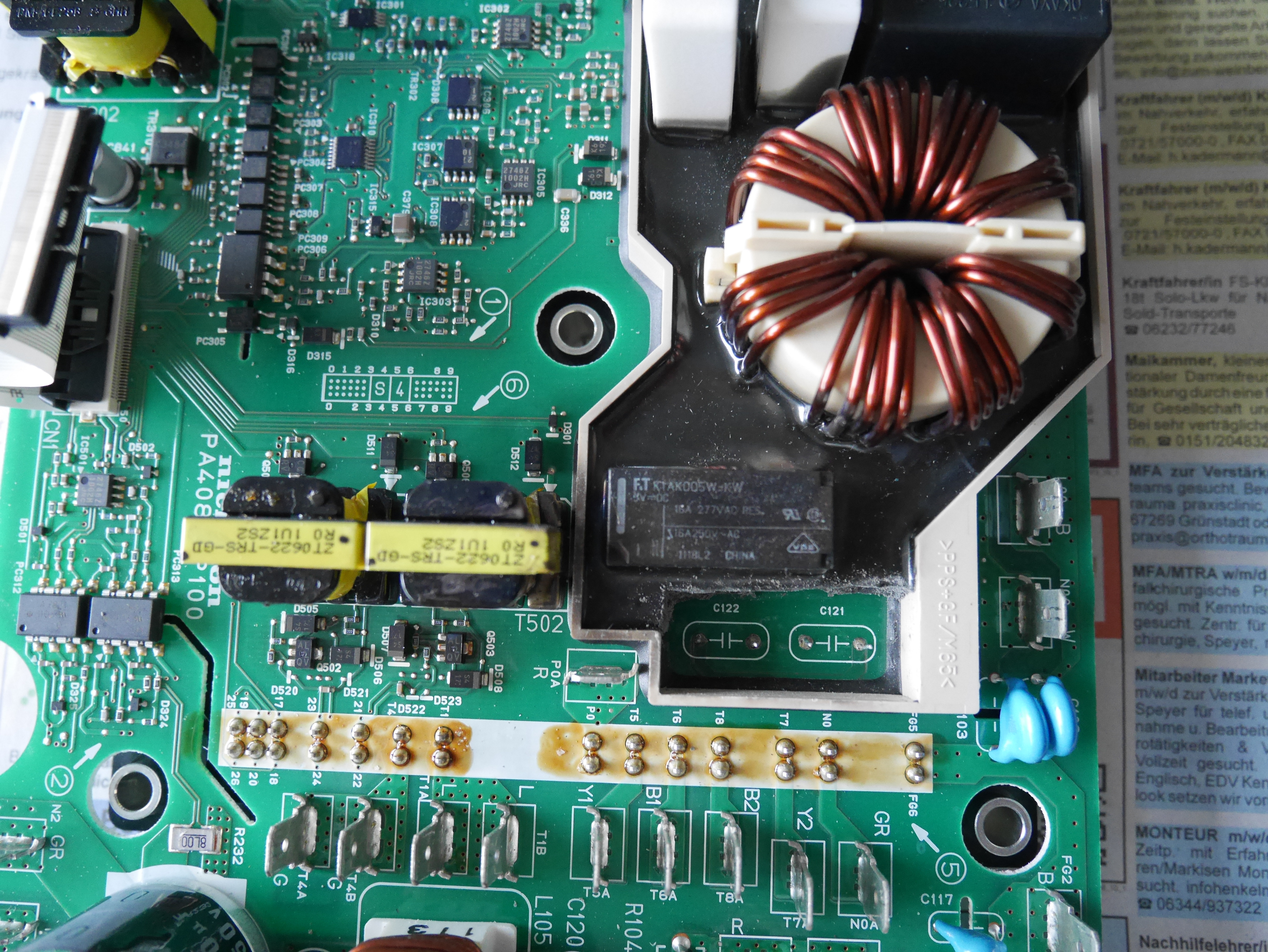
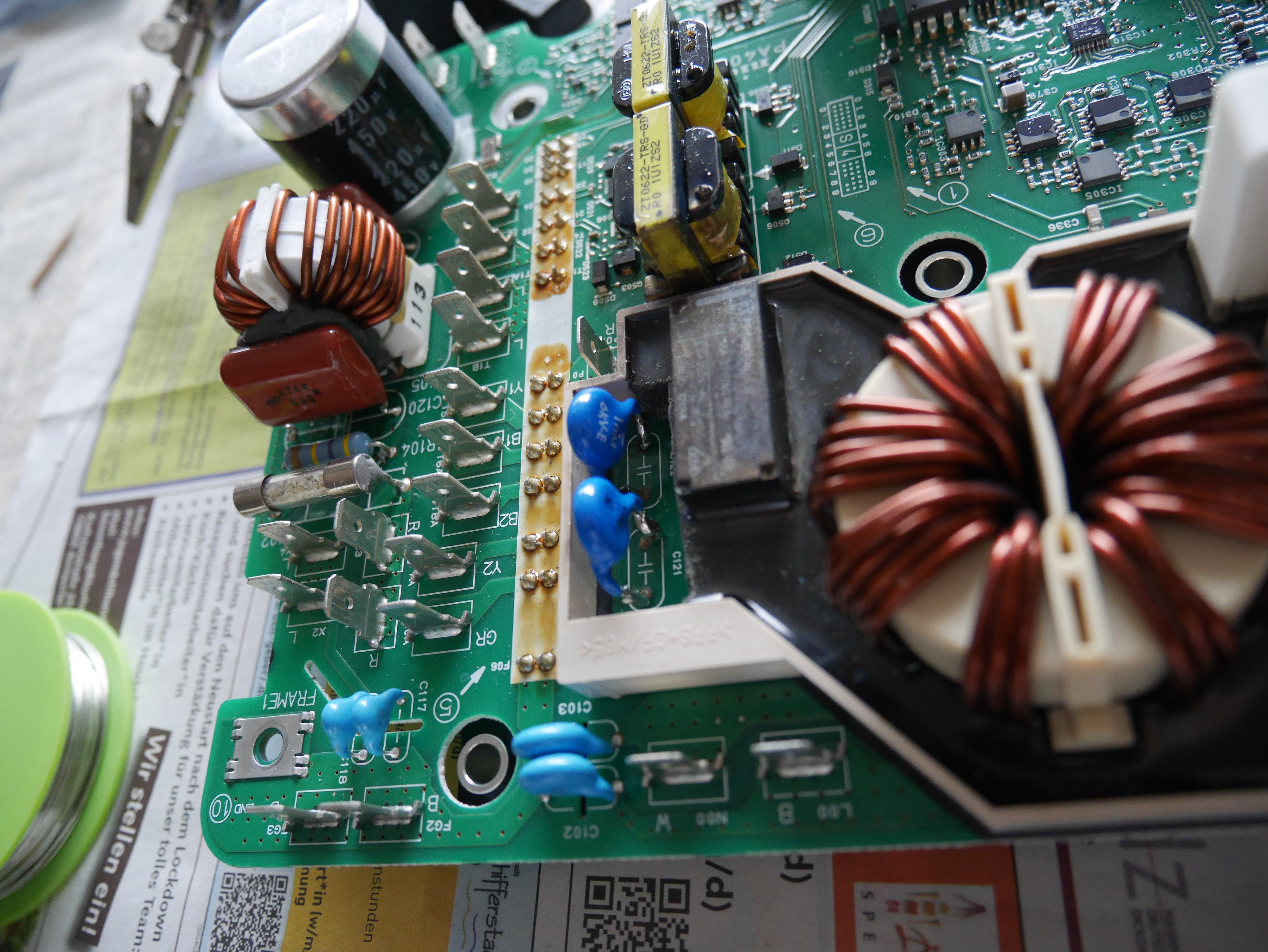
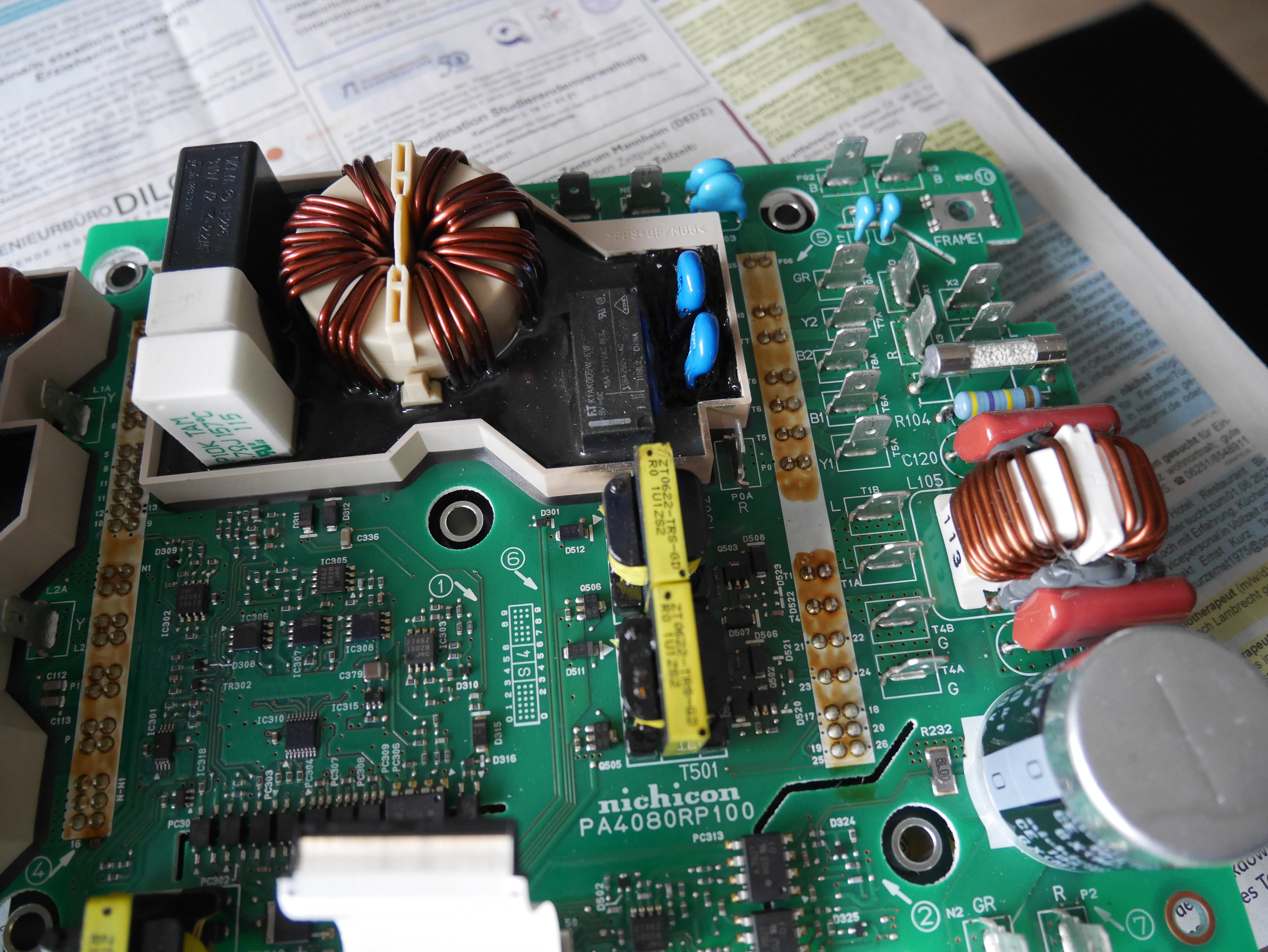
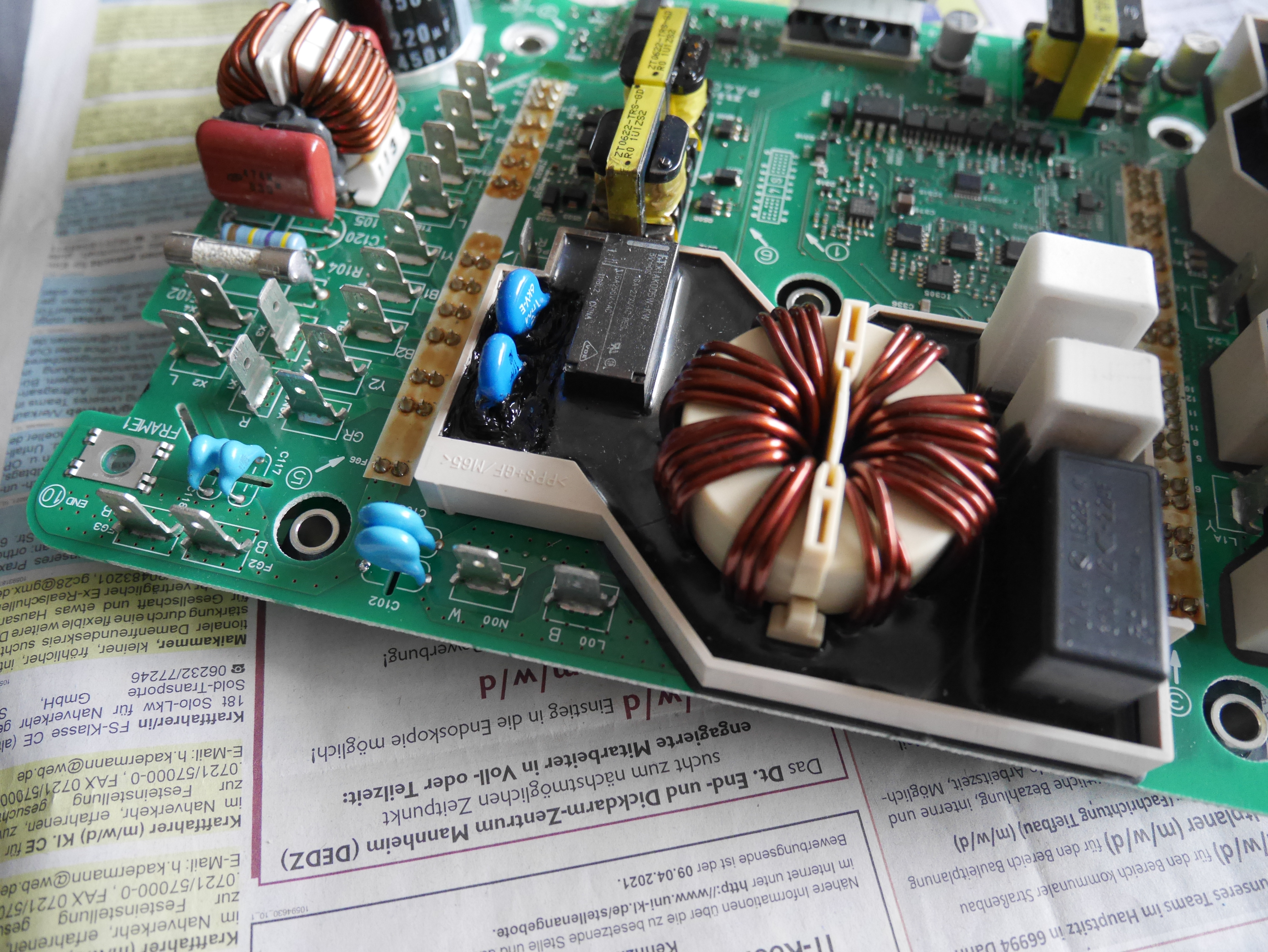
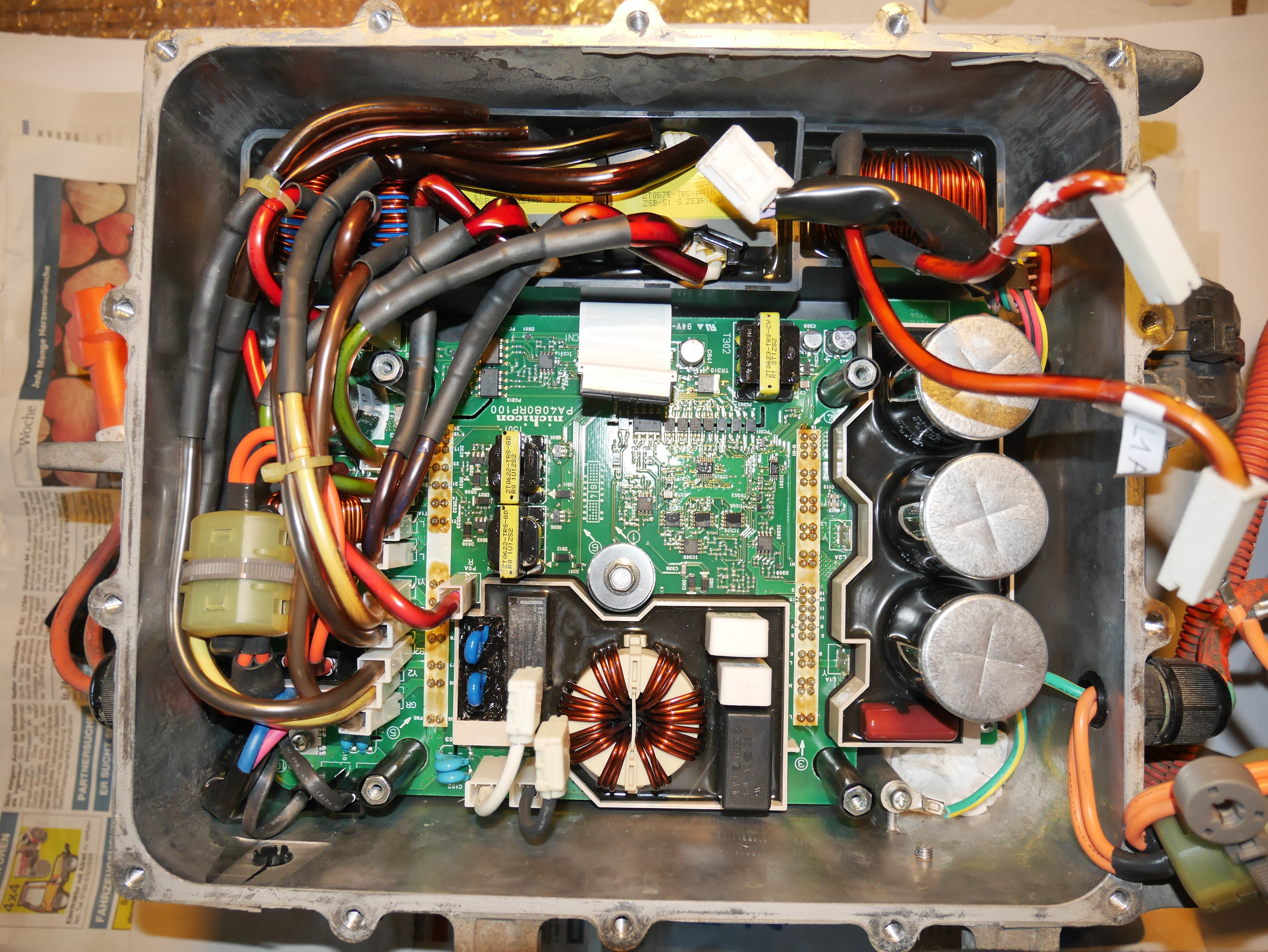
As I had measured good values on all “power board tests” being suggested in this thread, I hadn’t taken into consideration that there could be problems on this, so I hadn’t taken many pictures except of the ones I took when I replaced the snubber caps. Still, I want to share with you what I have, maybe you find an abnormality just by a visual inspection of the, I admit, not really good photo material:

Power board at very first opening of the OBC. You easily see the blown subber cap.
YWz1KRZ.jpg


Resistance test. Lying next to the OBC on the left side, you can see the battery pack (@ 4.4V) used for the successful relay test on D301.
fpYzqVy.jpg


Power board out of the box.
8g7GdBS.jpg


Next pictures all illustrate subber caps damage and replacement, but you always see a part of the surroundings, too.
JPJXMSK.jpg

gVAo2P7.jpg

kzhTyu9.jpg

m7unpbO.jpg

FuJqpV8.jpg

WnPc7L7.jpg

0HtqjJb.jpg

yOiybSP.jpg

XkxFjqj.jpg


Reassembling the OBC.
xkmf2RG.jpg


Beside of that, some additional information I might have given before.
The car goes to “READY”. When READY, there is no warning light showing up on the dashboard, warning lights only go on at the beginning of the AC charging process until it is interrupted after a couple of seconds. When READY, auxiliary battery in the front of the car gets charged (voltage rising to > 14V).
When I plug the EVSE cable into the car to start an AC charge, There is an audible “clicking” noise from the box on the EVSE cable. The charge light on this EVSE box switches on (besides of the ready light that is on all the time). When the charge is interrupted after some seconds the charge light switches off and there is again a very similar noise to be heard, emitted by the EVSE box. The fault light, that is also present on the EVSE as a potential third indicator, stays off all the time.

We can go on troubleshooting in the objective of getting a better understanding and a better knowledge of how these two charger boards work and interact, but for the repair of the car, my plan A is now to replace the whole OBC by an OBC from a scrapyard. After the findings on control board 1, I fear what we could find on the power board and this is too much of an open end for me...
 
That the car goes to READY rules out a cell/pack fault that could prevent charging. The DCDC is working so the 20A fuse in the MCU is intact.

That is good test data on FB706, it is open and confirms that no voltage is passed from the main 5V buss thru FB706 to the 5V leg serviced from C840. The return or ground side of all the supplies is at the same reference point so there can be coupling and strange meter readings as you have seen.

Good set of pictures, will zoom in and inspect for damage.

Your EVSE seems to be starting (the relay engaged) which means that the car is communicating from the control board and EVECU to give it the go signal. Then when the fault is detected, it is commanded to shut off. This would not occur with a bad control board, so i think board#2 is trying to do its job.

Your symptoms make me think that there is no AC getting to the power board. i noticed that you labelled all the wires so you likely put them all back correctly. The DTC would tell if this was the fault, then it could be traced to either an internal or external reason.

When you did the repairs,
did you check the HV output fuse on the power board, F102?
Did you do the diode check of the waffle plate?

Things to check/verify:
That the AC wires from the J1772 port to the OBC are intact and have continuity.
Take a look inside the EMI filter doghouse on top of the OBC cover, there is a fuse in there.


Your OBC failure was quite an energetic explosion. i noticed possible wire varnish damage on the AC filter inductor in the potted doghouse, and possible damage to the gate drive transformer T502.
 
I had problem with charger again. Same symptoms as before. I found that my installed resistor are dead. I    changed it again and charger started to work. I hope I will not have this problem again.
 
Looking back i see that your OBC had quite an energetic failure. Did you inspect the bottom side of the control board for damage or metal splatter that might short out the tiny pins on ics, such as iOnico had in his failure shown earlier on this page.

Did you replace the AC relay near the snubber caps? If that relay opens or chatters during charging then the entire mains voltage gets carried by the ceramic resistors. i wonder if the relay should be changed whenever there is a failure of the ceramics.

attachment.php
 
I inspect board and I didn't find anything suspicions. No I didn't change relay, but I did check it and I did not found anything bad about it.
 
After some weeks of silence, I’m back for an update. I must admit that I have given up further troubleshooting. The next steps would have needed to find a tool to read the DTCs and very likely to get the power board separated from the waffle plate. Two obstacles that finally seemed too big after I had found an OBC box from a scrapyard in Norway (should arrive within the next days) that had the identical codes as my one on the part number sticker. So, this should be a 1:1 replacement and I don’t see what could go wrong here. Still there are some variants and options on how I could do the repair and I’m not completely certain which variant to choose and which option to realise:
  1. I can take out the whole box and exchange it again the “new” box. This implies to disconnect all these not easy to open connectors and the hoses for the coolant fluid. This is the disadvantage of this variant.
  2. I can just exchange the two damaged boards (the OBC power board (including its waffle plate) and the OBC control board 1) against these same two boards from the “new” box. I would only have to work inside the box and could let all teh connections and hoses in place.
  3. The new OBC power board should come with two intact snubber caps. But they are those that had been put on the board at the factory and everyone on this thread knows that bad things can happen to them. Would you consider replacing intact snubber caps as a precaution (replacing them by caps being able to stand a higher voltage)?
  4. When you saw my pictures about the damage on the downside of the control board, kiev, you shared the idea to add a splatter shield between snubber caps and control board or somehow around the snubber caps. How would you “design” such a protection? What material would you use? And would it also be a protection against arcing?
I also had some thoughts beyond these technical details and my own repair:
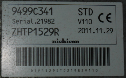
Finding an OBC box about which I was sure it is completely compatible wasn’t that easy. Actually, as I don’t know how OBC boxes having different part numbers differ, I really only was looking for one having the exactly identical numbers. In my case this was:
57gnycW.jpg

This approach pretty much limits the choice. Actually, I was happy about just finding one! I’m pretty sure that if I had had the repair done at the Peugeot dealership, they would have replaced it by a newer box, having different codes but also being compatible. As they have access to the substitution history of these part, they would just have picked the most recent compatible version of the OBC box. Now my question is, does anyone know the “substitution history” for the OBC box? If information about this would be accessible, it would make easier the repair in situations where a complete replacement is the last solution.
Besides of the numbers on the picture above (I’m still confused about the fact that there are two numbers, if one is the part number, what stands the other one for? Or is one the part number of the OBC and the other one the part number of the DCDC converter, both being in the same box?), that are probably the numbers given by Nichicon, I also came across some OEM part numbers. I don’t know if these numbers have lasted in time, or if they also have been changed when the Nichicon numbers changed. I came across the numbers 5600VK and 1614389880 for the OBC box in the Peugeot iOn and the 1669678780 in the Citroen C-Zero. Thinking about it, it also could be that one of the two codes on the sticker on the box is the Mitsubishi part number... Wild guessing...
What would be great to have, is a cross reference table between the original Nichicon part number of the different versions and the OEM numbers assigned at their relabelling. That table should then also include information about backward compatibility, listing all (older) Nichicon part numbers that a (newer) version of the part could replace.
 
So I have problem again. This time other resistor died. I checked relay - I don't see problem with it. I applied 5v and I see resistant is dropping from 9.7Om to 0 Om. I changed both resistors and this time I used 10w resistors. But some how charging doesn't start. How to check what is wrong? I see 120v input, I hear relay clicking, after 2 seconds relay clicking again and that is it.
 
If you could read the DTCs then it would provide the OBC fault information. This is the best approach.

Other approaches:
Check all the fuses in OBC and MCU.

Make a visual inspection to check for blown capacitors on the AC input path and the DC output path.

Perform the diode check of the waffle plate junctions looking for shorts or opens in the main functions, AC input rectifier, PFC switching and DC boost, PWM switching inverter, and HV output rectifier.

It could be a fault on the control board. This was an issue on iOnico's board after the snubber caps exploded and splattered molten metal.
 
Greetings all - it seems like it is my turn for the OBC problem. I have a 2010 iMiev which I've owned for almost 18 months - one of the early models imported to Australia which charges direct from the wall socket without a EVSE module in the charge cable. It has performed flawlessly since I bought it and is a joy to drive. A couple of nights back it was charging overnight as usual, but it dropped out about 90 minutes into the charge, tripping the RCD on my charge point. I didn't notice until I was most of the way to work the following day and realized the battery was considerably lower than usual. I checked things out when I got home, and determined that the problem was in the car, not the cabling. Connecting mains to the car did nothing at all - no charge light and none of the usual charge starting sounds - just silence. I looked back on my OVMS log and determined that the 12V battery was still charging during driving the day after the drop out - suggesting that the DC/DC converter is still alive.

Tonight I finally had an opportunity to pop a few lids and take a good look. The plate reads:
9499A758 13A
Serial.01202 V1.01
ZHTP1500E 2010.08.17
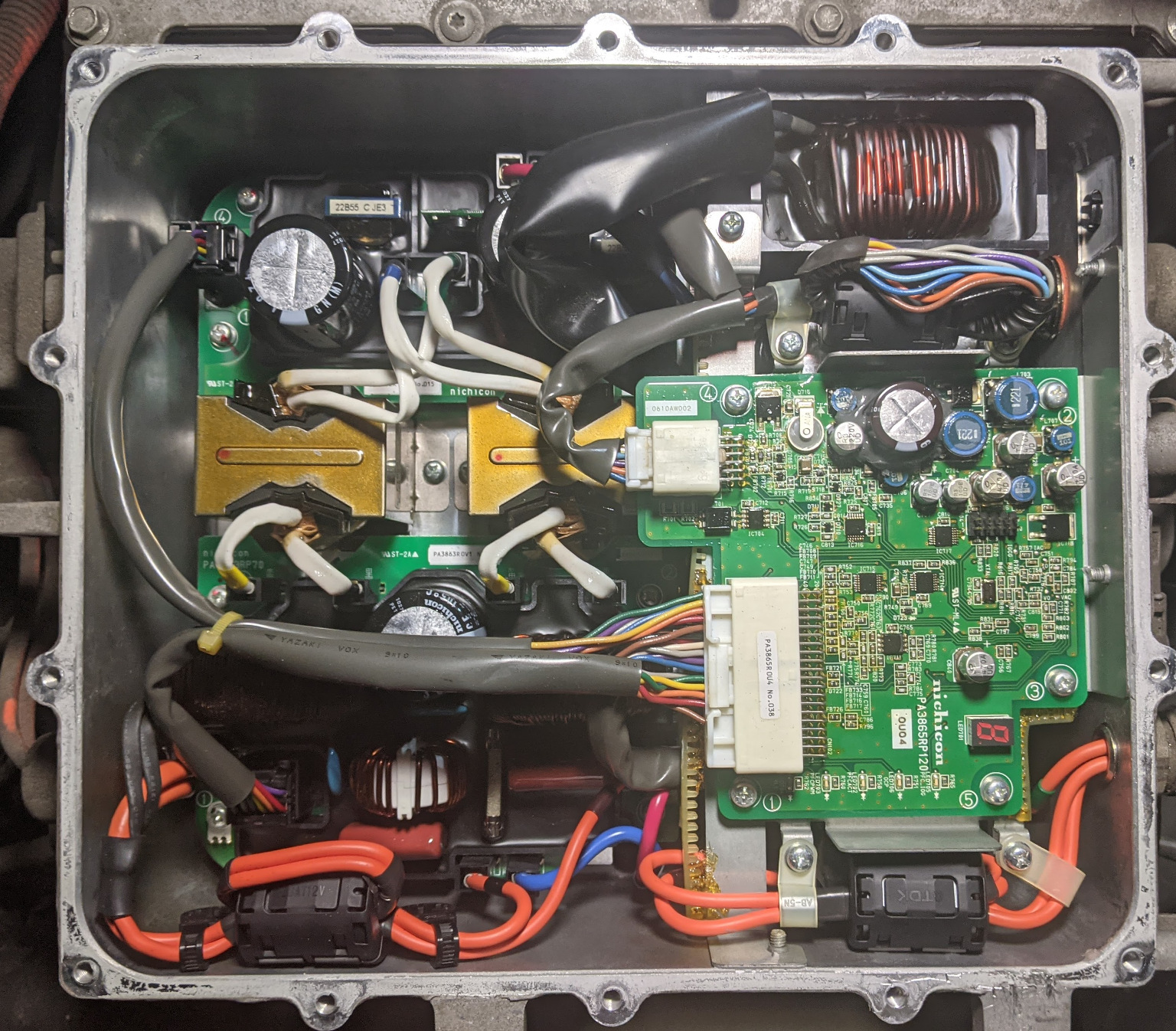
When I opened the lid the all too familiar smell of electronic death greeted me, but there are no obvious failed components on the visible parts of the boards. Here's an interior view of the unit - not like any of the photos I've seen in this thread so far (though there are so many it is possible I've missed one somewhere). Note the 7 segment LED display at the lower right!

c13ccfl.jpg


So, has anyone seen one of these before, or am I starting a new round of reverse engineering?
 
Wow that is interesting, never knew anything about the earlier versions. i think you will be starting a new round.

i like that the control board is using solid connectors with actual wires (similar to used in the Leaf) rather than the flimsy tiny plastic foil to connect to the power board.

There is a 10-pin black header on the control board, maybe a JTAG programming port. Someone clever could probably use that to get a reading of the firmware.

Much of it looks familiar, PFC boost inductor in the upper right corner, the two PWM inverter transformers on the left center, the HVDC exits at the bottom left from the Red (+) and Blue(-) jumper wire to the orange wires.

There doesn't appear to be a lot of heat or thermal discoloration.

Check the fuses.

What shows up on the LED digit when you plug it in to charge? Maybe it is an error indicator?
 
Ah well, interesting is more fun than easy, most of the time. :D

My next opportunity to work on the problem will be on the weekend, so at that point I'll take a look at the 7 segment display when powered to see what I can see, check every fuse I can see (have already checked the 20A fuse and it's good - not unexpected), and then go through the whole isolate/drain coolant/remove box process and get it on the bench for a pull down and a detailed examination.

That's an interesting point on the possible JTAG connector - I hadn't noticed it in my eagerness to find burnt componentry in the cool of a Perth evening. I'll have a closer look once the board is out of the vehicle, and if possible connect it up and see what is there.
 
Before you go to all the trouble to remove the unit, It may be that you could leave it mounted in the car and just remove the control board to see if there is a blown capacitor or whatever is below it. i noticed that they used the numbering sequence on the screws--just start at 1 and follow the sequence.

The AC rectifier section is underneath the control board, possibly more such as EMI filter and fuse..?

Also you could remove the connectors and move the wiring harnesses such that you can see what is below them--maybe some hidden damage.

It looks like all the boards and components could be removed with the OBC in place. There is likely some large transistors and diodes mounted below the boards against the coolant plate heatsink.
 
Today's progress on my OBC problem.

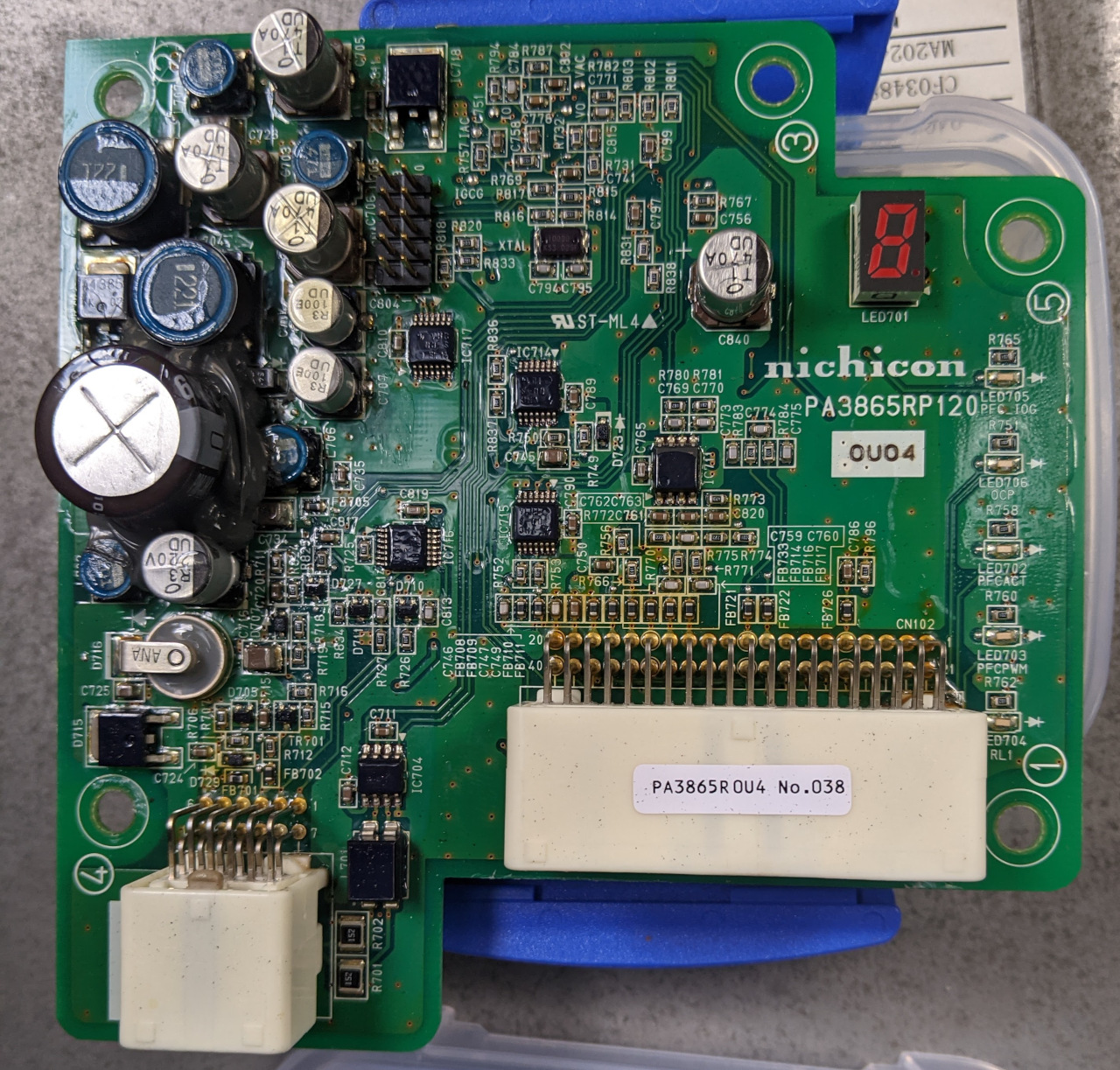
I started by trying to make the 7 segment display on the control board show something - and in the process noticed that there are also five single LEDs down that edge of that card - conveniently labelled on the silkscreen as PFC_IOG, OCP, PFCACT, PFCPWM, and RL1. None of them or the 7 seg display showed any signs of life - I tried applying charging power, and also turned on the ignition.

After this, and in the absence of my OBDII dongle (loaned out to help another sick iMiev) I decided to see if I could remove the OBC boards without draining coolant and pulling the whole installation out. Of course I isolated both the main and aux batteries before doing anything, and also did some careful probing with my DMM to make sure nothing still held any surprises.

The control logic board came out very easily, revealing an aluminium mount/heat shield beneath it.
40kLbGb.jpg

This was a little harder to remove, as three of the mounting screws are fitted through the side of the housing (and are sealed with silicone). I had to use an offset screwdriver for the last one which was inconveniently located behind the coolant reservoir. After the mount plate was removed all of the boards were visible, and could be easily removed after wiring was disconnected.


Photos of the various boards follow. An initial look hasn't shown any evidence of failed/burned components. I thought a capacitor had gone but it turned out to be just a splash of potting compound over the top of it.

Front of control board:
bJKlNNk.jpg


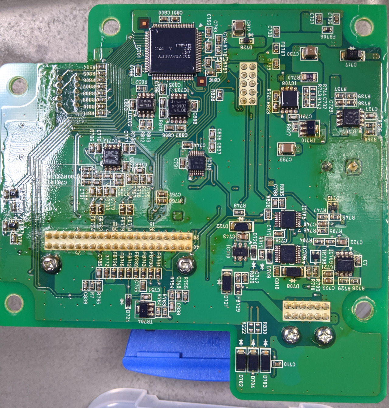
Rear of control board
MgTpSQu.jpg


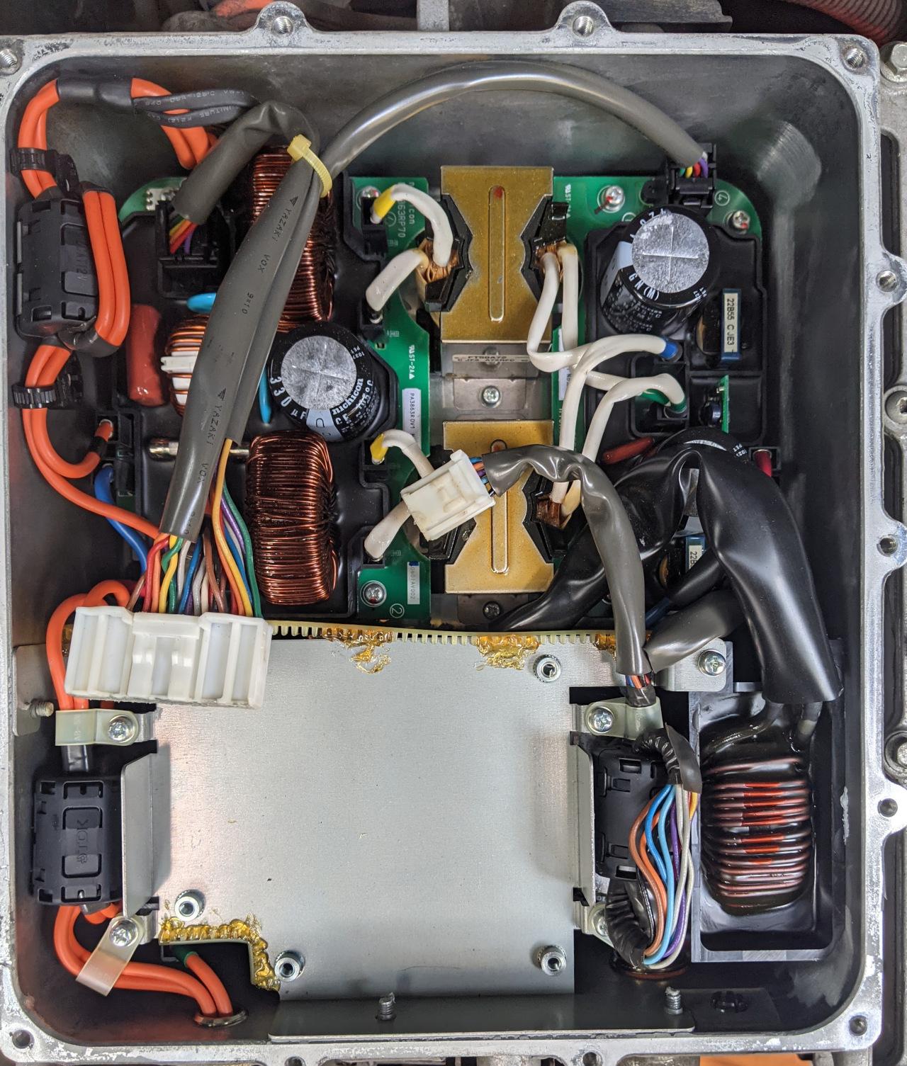
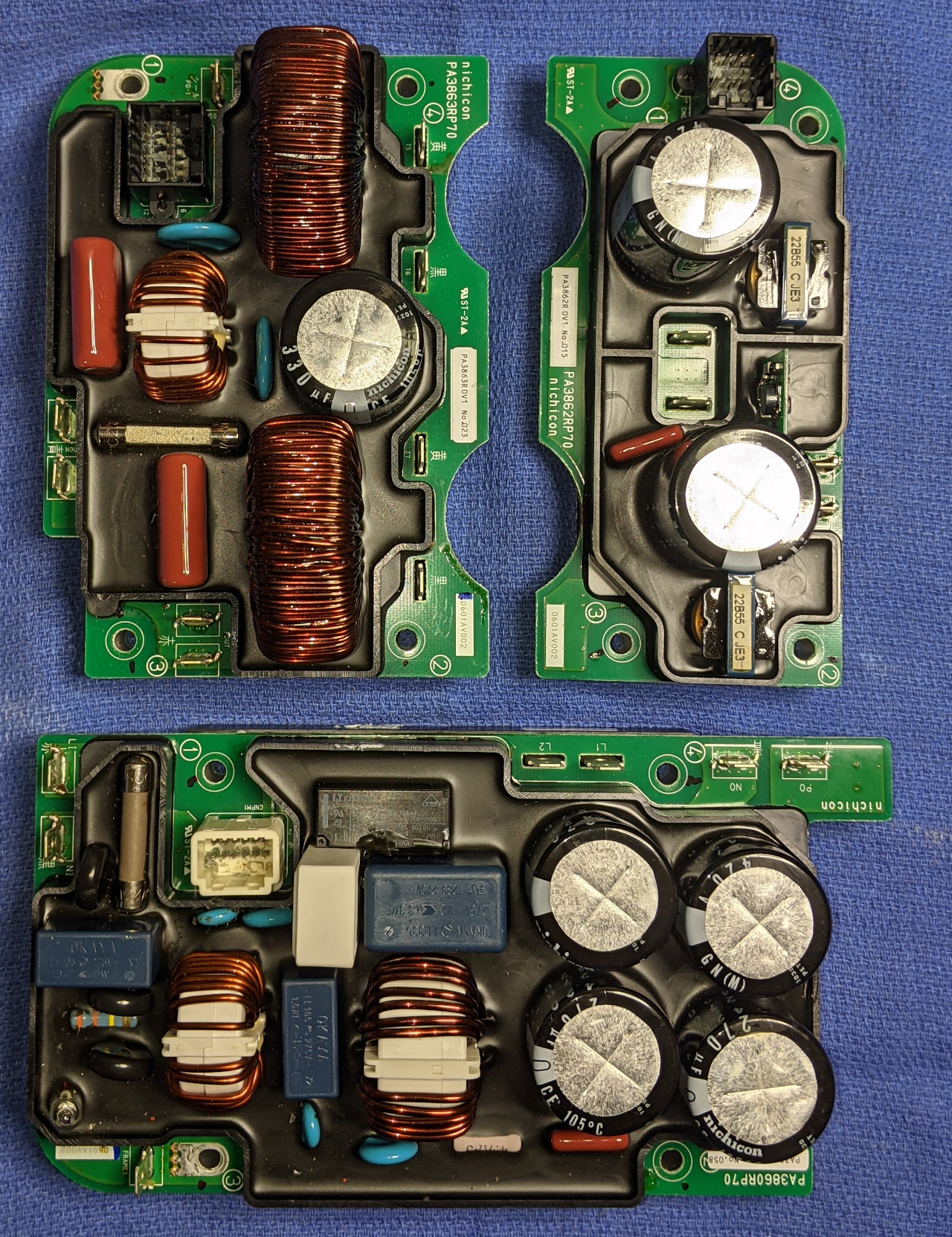
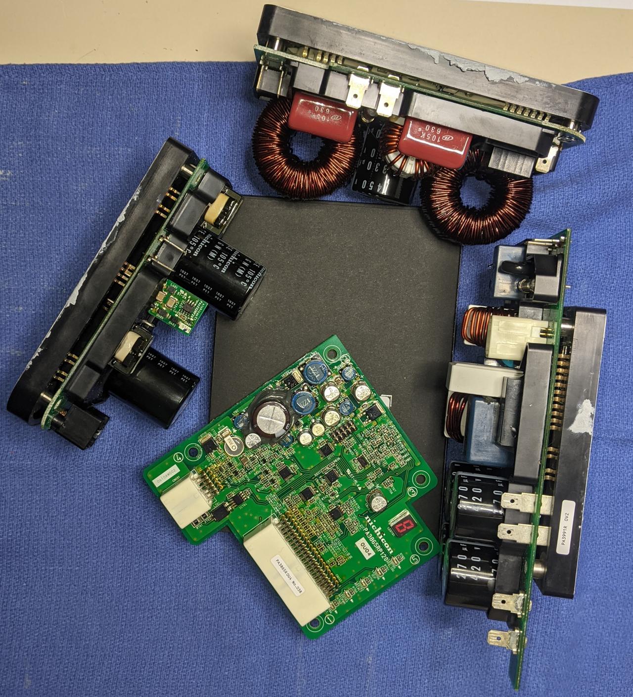
Power boards in same orientation as in bottom of box, with front of car is at top - control board would be above the lower left. All of the power boards appear to have their own junior waffle plates.
0JbS3rG.jpg


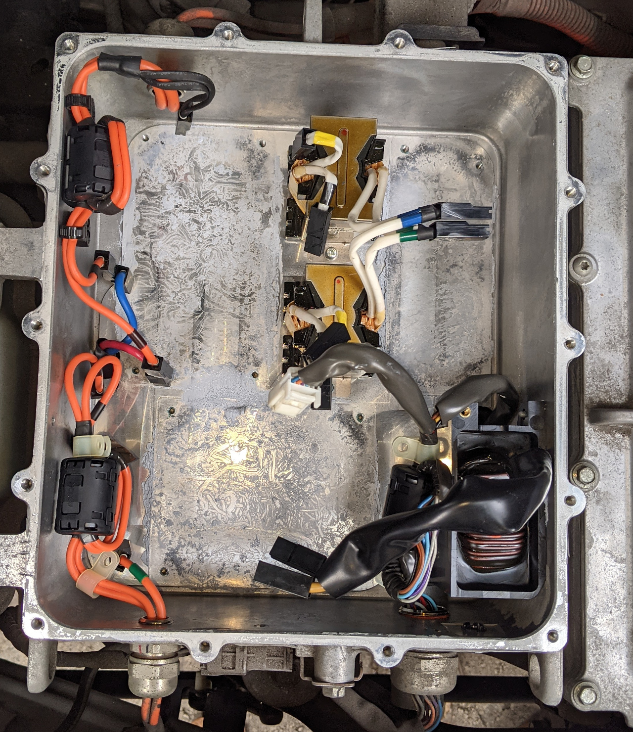
Box after boards removed. Note monster inductor and two fairly chunky transformers remain.
L9gqYKC.jpg


I'm a little surprised that nothing was showing on the control board LEDs - you'd think at least one would come up. I've since checked the 10A fuse under the bonnet whichfrom the manual appears to feed DC to the module - it appears ok. None of the obvious fuses in the modules are blown, and I cannot find a surface mount fuse on the control board at this point. It might be under the blobs of silastic on the power supply section.
 
Nicely dissected. There is a dark looking fuse on the AC input board, but otherwise it is too bad that there is nothing obviously broken.

Do you know the wire colors and pinout of the input control harness? i would say that you are not getting one or more of the 12V supplies or the command signals to the control board, and that you should check and verify that the harness leading to the OBC is all good and no broken or chewed wires.

i see quite a bit of functional commonality with the 2012 version even though different pcb.

2010 version has 3 separate power boards plus 1 control board
PA38nn Board Numbering, where nn is:
65 = Control board
60 = AC Input, Fuse, EMI filter, Relay, Rectifier, PFC, LC Boost to create P0,N0
62 = PWM Switching Inverter
63 = DC Output Board, Rectifier, EMI filter, Output fuse, Feed to DC/DC

There may be a 12V feed that is Hot All the Time, like a small keep-alive or standby power source, then another that is switched thru a relay by a control line from the EV-ECU, which would be the Turn On and Operate supply. Then possibly some discrete lines and some CAN buss lines for commands and data.
 
philsuth said:
Photos of the various boards follow. An initial look hasn't shown any evidence of failed/burned components.
Could we see photos of the back of the AC input and PWM boards, please? Presumably, the power transistors and diodes are on there, pushed against the back case for heat transfer. We might be able to spot damage to some of them, or some minor component that is preventing power from getting to the diagnostic LEDs and whatever drives them.
 
coulomb said:
Could we see photos of the back of the AC input and PWM boards, please?
Unfortunately there's not a lot to see without doing a fair amount of picking and desoldering - all three power boards are stacked like this. I've peered in between the boards as best I can and cannot see any craters or broken devices, but this is far from conclusive.
IHx7oy0.jpg

My next move is going to be to reassemble the unit and (carefully) have a look at what is going on when the unit is connected to the car.
 
Back
Top