Thanks for the reference values of the resistors, Kenny.
It seems we're on a promising spot there... I measured the resistance through the 3 resistors and all are way off of what they should be:
R721: 167 Ω (should measure 1 kΩ)
R720: 17 Ω (should measure 5 kΩ)
R576: 15 Ω (should measure 5 kΩ)
I don’t know if something could happen that reduces the resistance of a resistor. I’d rather suppose that if a resistor is damaged it goes open circuit. But this would mean that somehow there must be something acting as additional resistors in parallel to the checked resistors. That raised my interest in the IC509.
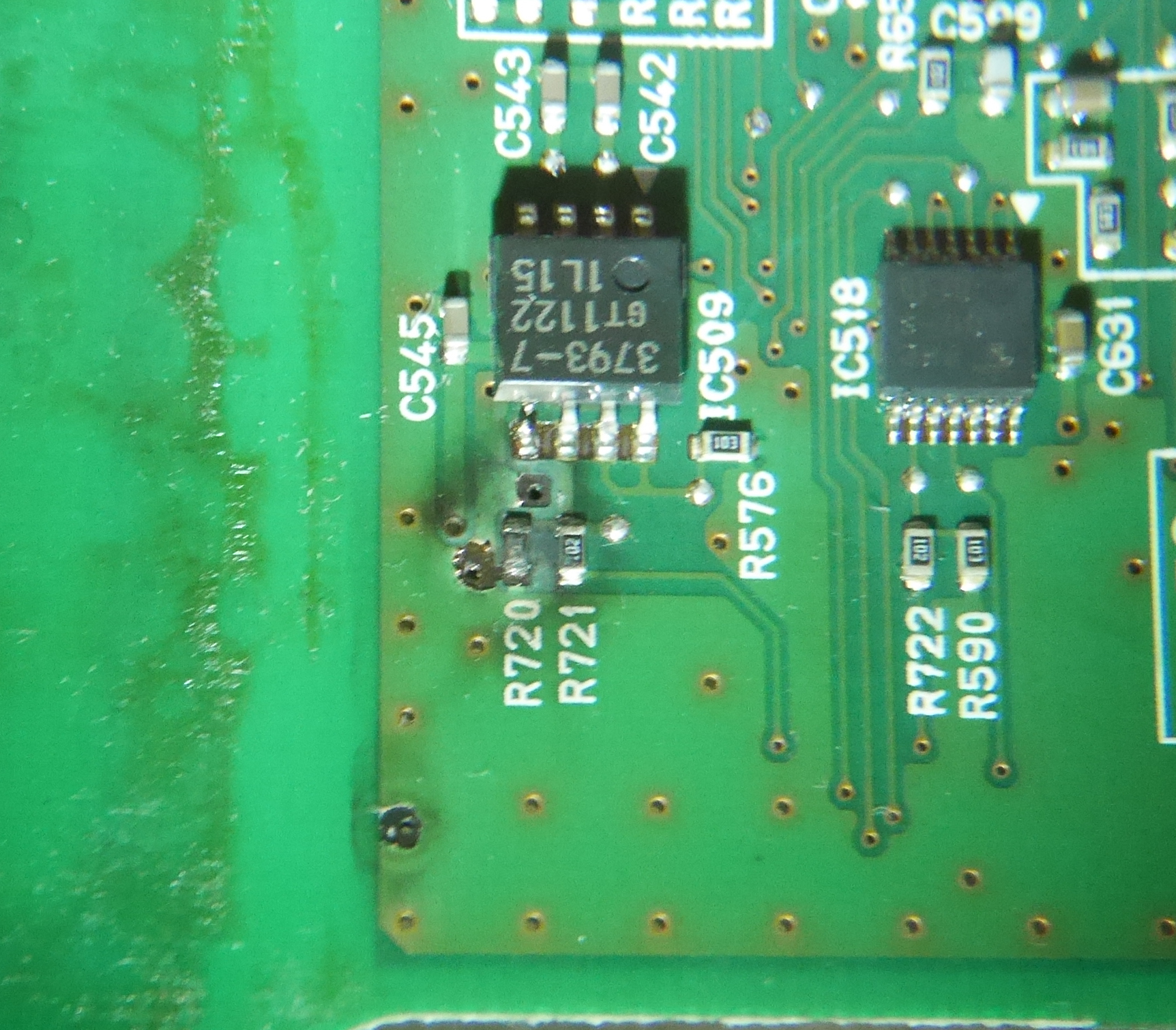
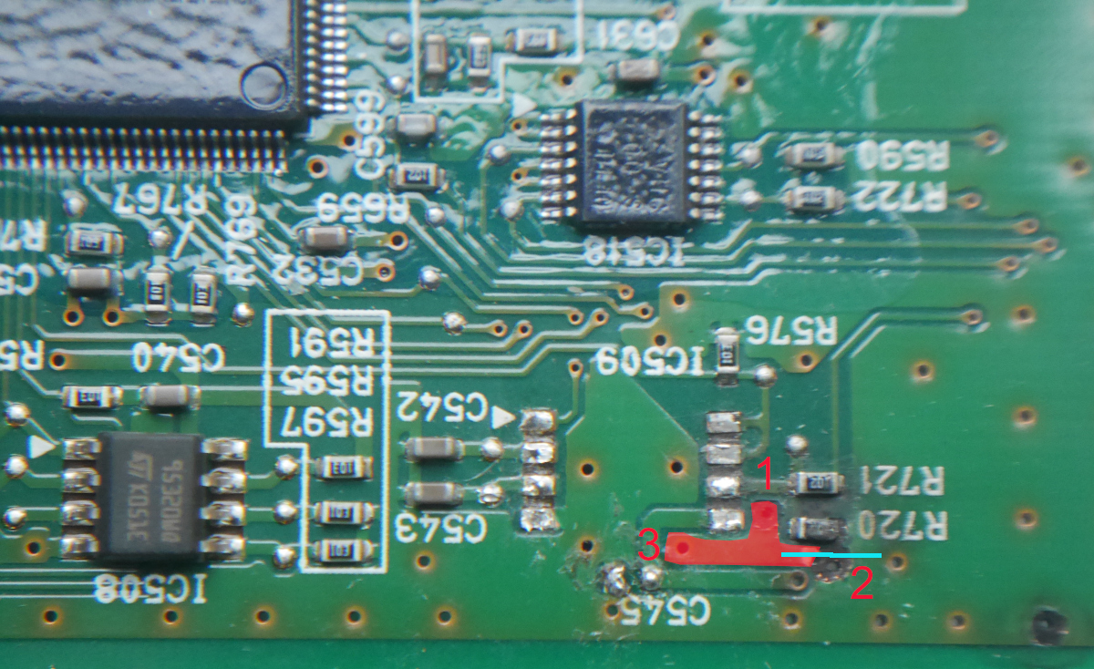
Turning the board in all directions and looking at it from different perspectives I noticed that a pin of the IC509 seems to be broken: the pin next to the resistor R720. Not easy to see, even with magnifying glass. I thought until now, that it was just due to some reflection of light on the solder that it didn’t exactly look like the pins next to it (see 2nd picture in my last post or picture later in this post). But actually there’s a real interruption between the solder pad and the entry of the pin into the IC plastic body. The measured resistance between the solder pad and the part of the pin that sticks out of the IC’s body is 8.9 kΩ. Finding some helpful information in
this post, I identified the IC as being a
MB3793-45PNF. The broken lead is the one of the VCC pin (bin number 5). I first thought to try to just bridge the break to see if this would influence the resistance values in a positive way. But thinking about it, I found no physical reason why this should be the case. What seems more likely is that the IC is more severely damaged and is the troublemaker in this circuit.
I’ve measured some resistances from pin to pin for comparison. On the broken pin I measured from the solder pad (“VCC solder pad”) as well as from the little piece of lead coming out of the IC’s body (“VCC rest”). I added the pin numbers in brackets accordingly to the datasheet.
VCC solder pad (5) – VCC rest (5): 8.91 kΩ
VCC solder pad (5) – Ground (4): 3.7 Ω
VCC rest (5) – Ground (4): 8.91 kΩ
Ground (4) – Clock1 (8) and Ground (4) – Clock2 (7): 16 Ω
Ground (4) – INH (6): 18 Ω
VCC solder pad (5) – Reset (1) and VCC rest (5) – Reset (1) and Ground (4) – Reset (1): 39 MΩ
VCC rest (5) – Clock1 (8) and VCC rest (5) – Clock2 (7) and VCC rest (5) – INH (6): 8.91 kΩ
I also measured a resistance of 3.4 Ω between R720 (at the side with the “R720” inscription) and the C545 (at the side being under the “4” of the inscription “C545”).
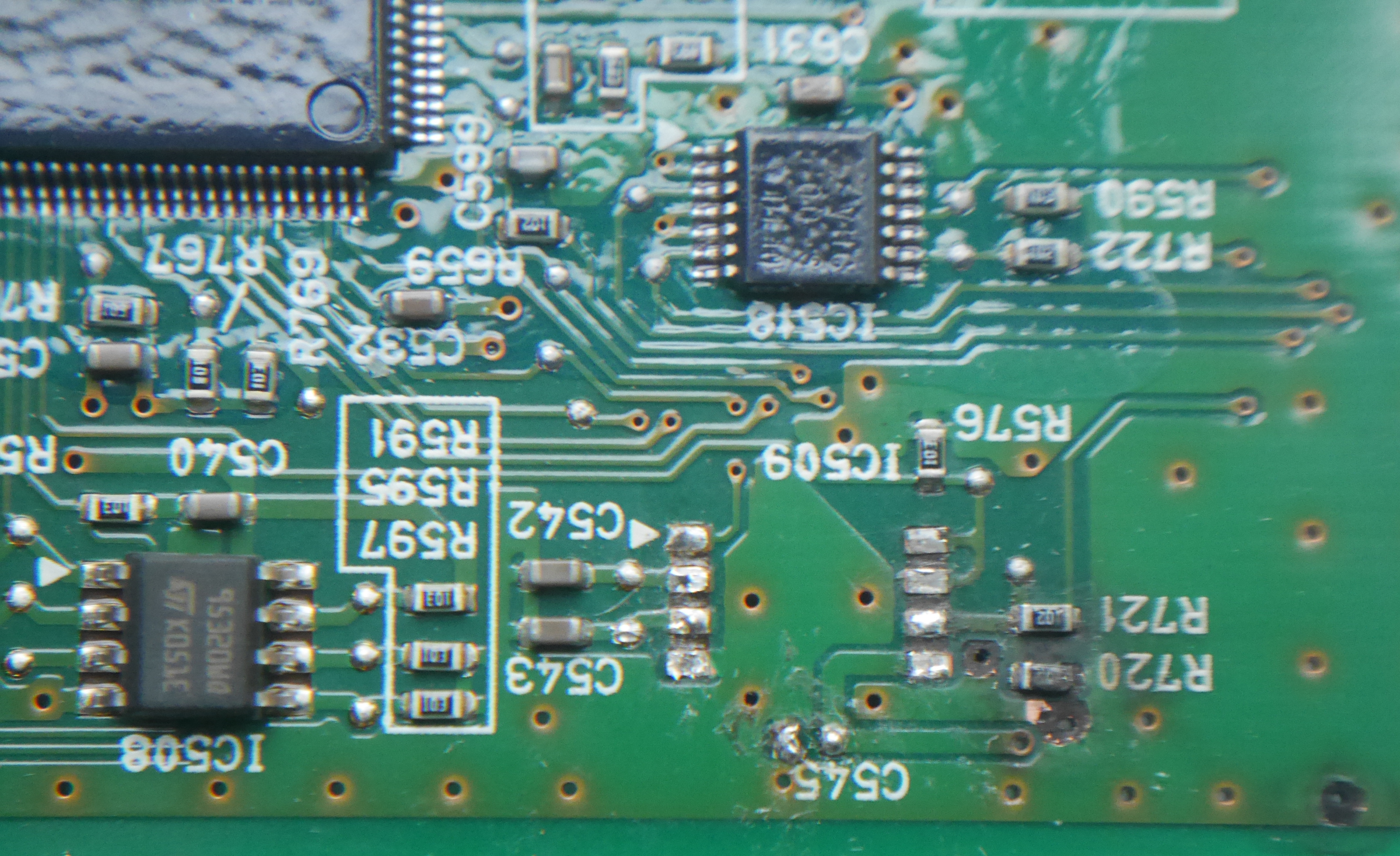
For some other measurements I added the values measured in the following picture, as it was hard to describe for some, from where to where I had taken the measure. The colours of the lines and measures I added don’t have a meaning. It was just for better differentiation. Opening the picture in an new tab will allow to significantly enlarge it.
The first picture shows the concerned area of the control board as it should look like without being damaged (taken from another picture on this forum). The second picture is a picture of the same area on my board and the third is the same as the second but with the measured values added.

Without knowing the values I should have measured for these connections, every possible explanation is quite speculative. Very suspicious is this little resistance between the VCC solder pad and Ground... What may have happened to damage the control board in this manner, is that when the capacitor of the power board popped a high voltage has been searching its way to Ground, creating high discharges to the 3 points of the control board where the green coating (and the copper below) has been removed (two of these impacts are next to R720) and to the N00-connector (see pictures below, connector NOO being in the bottom part of the 1st and on the left side of the 2nd picture, that shows it in comparison to L00 connector). That area around the N00-connector was also pretty black before I cleaned it.
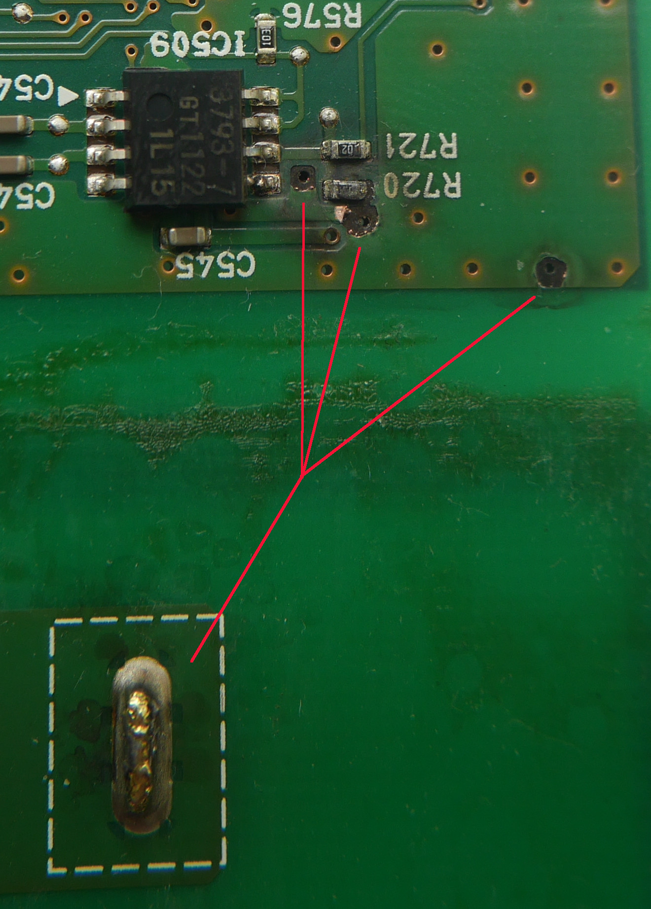
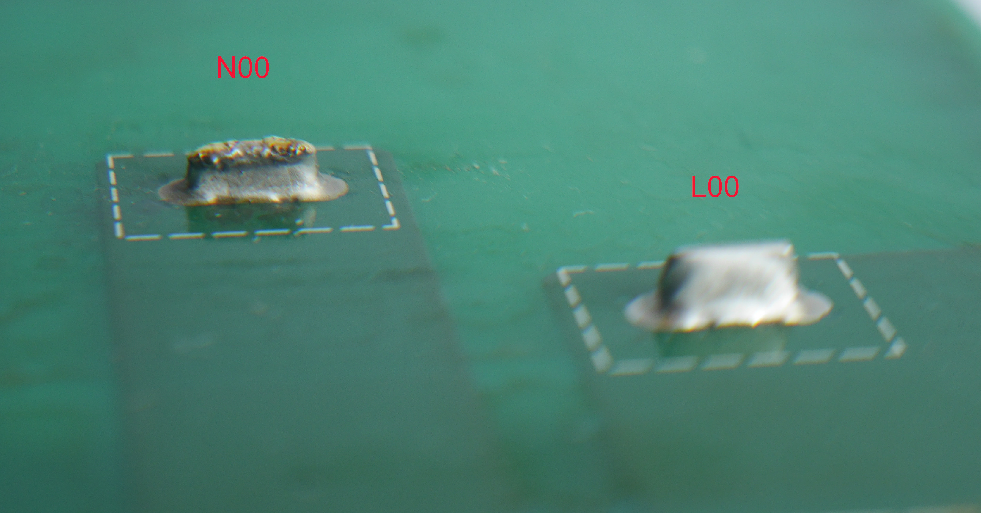
I guess that it’s very likely that IC509 is severely damaged and needs to be replaced. Concerning the resistors I’m not sure yet – if the discharge looked for a way towards ground, there’s no reason why it should have taken the way through one of the resistors, but the impact may have damaged at least two of the three mechanically. Also, I don’t know what to think about the low resistance between the solder pad of the VCC entry of the IC509 and Ground. With only 3. 7 Ω the resistance is very low and can’t be explained by what happens inside the IC as the lead is broken and the VCC solder pad has no contact to the IC (at least not through the VCC lead). Could it be a damage in the PCB itself? And if it is, how to find and repair it?
I’ve spent a couple of hours looking for where to buy a replacement for IC MB3793-45PNF. The MB3793-45PNF is obsolete since 2018 and none of the usual vendors does still sell it. So, I had been thinking about taking a very similar brother of it (the
MB3793-45DPNF – the “D” in the part number stands for “open Drain”) and adding a pull up resistor (between VCC and Reset pin) to give him the same functional behaviour as the MB3793-45PNF has, with a CMOS logic implemented. A 100k resistor could be used as pull-up resistor in such a circuit. Should be working, no?
Ok thanks for clarifying the question about the codes. I probably should go to the dealership again for the next reading of DTCs. Or better would be to find a tool that would enable me to do the reading by myself, but I still don’t know what tool would work for certain on the iOn.
Concerning the charge process I had done a rough description of what happens in
this post:
when I put the AC-charger-plug into the car, the ventilation starts instantly for 2 or 3 seconds and on dash the “red plug”-symbol starts blinking. After 5 seconds the “yellow car with the exclamation mark”- symbol lights up. After another second the “yellow car with the exclamation mark”- symbol and the “red plug”-symbol turn durably off.
I also have the following two short videos for further illustration. In the first you can see what happens on dash. On the second what happens on the EVSE. Unfortunately, I haven’t filmed the EVSE again after the interruption of charging. From memory I can’t say if the “fault”-light lights up or if just the “charge”-light goes off when the process stops. As far as I remember the “red plug”-dash-symbol’s normal behaviour is to be continuously on during charge and not to be blinking.
Video 1: https://i.imgur.com/eONlndi.mp4
Video 2: https://i.imgur.com/AXHYQEz.mp4


