The Troubleshooting and Repair for On-board Charger (OBC) Thread

Mitsubishi i-MiEV Forum

Help Support Mitsubishi i-MiEV Forum:

This site may earn a commission from merchant affiliate links, including eBay, Amazon, and others.
philsuth said:
Unfortunately there's not a lot to see without doing a fair amount of picking and desoldering - all three power boards are stacked like this.
Ah! Mini Waffle Plates™!! If they are anything like the single Waffle Plate™ in the later charrgers, the semiconductors will be under a very hard resin-like potting material that will be next to impossible to remove. Someone actually got it X-rayed to find out what's actually in there.

CXEyQ5t.jpg


My next move is going to be to reassemble the unit and (carefully) have a look at what is going on when the unit is connected to the car.
Is this where you say "Gee, I wish I tagged all those wires so I know where they're supposed to go!" ? :shock:
 
By the way, do you happen to know either of these users, both from Western Australia? From the first page of this topic.

17. skylogger#2, 9/2018, 2010 in Western Australia, blown snubber caps and MCU fuse, AC relay and precharge Rs
[EDIT: REPAIRED--SUCCESS!, 9/2018 ]

13. skylogger, not charging in Western Australia, found blown surface mount capacitors.
[EDIT: SOLVED AND REPAIRED,8/12/2018, see picture of a twisted resistor causing open circuit on voltage monitoring]

11. mikedufty, 3/18, 2010 Australian model not charging fully in WA, charrger was replaced under recall. Dealer now pointing at EV-ECU as bad.
 
coulomb said:
By the way, do you happen to know either of these users, both from Western Australia? From the first page of this topic.
Alas no, though I do know someone who knows Mike. I joined the local chapter of AEVA at the same time as Covid landed, so opportunities to meet have been a little limited.

This last weekend I reassembled the chaarger, checked all of the connections very carefully, and powered it all up again. The problem is still there, but at least I don't appear to have made anything worse. The car is still drivable with no visible problems, and I took the opportunity to head across to UWA and prove that DC charging is still functional, if fairly slow.

I also checked the wiring between the J-1772 socket and the on board chaarger, and confirmed there were no problems or missing earth connections - mains should be making it into the chaarger box. Also put a Bluetooth OBD-II device and it shows no codes current. Interestingly there is a U111C code archived - BMU CAN timeout - so that makes it more likely that the control board is my problem. There is certainly 12V on a couple of the pins going to that board.

Next move will be to carefully check the charge controller board as I've still seen no LEDs active on it.
Thankfully it is easy to get to at the top there so I should be able to confirm power supply rails and so forth, and start looking for CAN comms.
 
That you don't hear the relays and pack contactors clacking indicates that the EV-ECU is not awake or sending the necessary commands to start the charging sequence. It is under the rear seat in the 2012.

Maybe the Proximity and Pilot functions reside in the OBC ? but the EV-ECU still needs to be active for charging and for driving. That it drives okay says that part of the EV-ECU is good.
 
kiev said:
That you don't hear the relays and pack contactors clacking indicates that the EV-ECU is not awake or sending the necessary commands to start the charging sequence. It is under the rear seat in the 2012.

Maybe the Proximity and Pilot functions reside in the OBC ? but the EV-ECU still needs to be active for charging and for driving. That it drives okay says that part of the EV-ECU is good.

Here's my thinking (and observations). Bear in mind that on this older unit there is no external charge control device, so mains power comes straight in to the vehicle connector from the wall. There are the usual switch and resistors in the charge connector for the proximity signal, which is then wired straight to the EV-ECU, so it knows when the charge cable is connected. I've checked this section of circuitry is working correctly by connecting an unpowered charge cable and confirming that a flashing charge light appears on the dash if I turn the key on. This makes me think that the EV-ECU is playing its part correctly.

When working properly, the relays and contactors are always silent until you actually apply mains power, at which point everything springs to life. To me this says that the EV-ECU somehow finds out that mains power is now present so it can wake all the necessary stuff up. The only module that deals with mains power is the OBC, so the 'always-on' part of the OBC must somehow signal the EV-ECU to indicate that there's power present, and then in response to that signal it wakes everything up (by pulling in relays A06X and A08X). I'm assuming this signalling is done by the control board pulling CHGP low. As most of the control board is presumably powered down there's no processor available to pulse it, as happens once everything is awake and charging commences.

I observe that there is absolutely no change in CHGP when mains power is applied. Admittedly I'm using a multimeter for this, but if for example it started pulsing I'd certainly see some even momentary change in voltage. This makes me think that the mechanism to detect the presence of charging power is broken, possibly due to a fault presumably on the power input board. I have removed the control board again to go over it thoroughly and try and determine on which pin the mains present feed comes in from.

Along the way today I have also confirmed that the CN101 pin numbering on my control board appears to match those already reverse-engineered from the newer units. I will write up some wiring colours and notes on this. Also, component IDs and types seem to largely match, when they are present. Almost every component on the control board is numbered in the 700-800 range (have found 4 exceptions, 1 of which is not fitted). And I've (just) found some labelled test points (IO, VO, VAC, IGCG) - which might be interesting to probe.
 
Have you tried charging using a different cable? Maybe the proximity and pilot signal generation within your handle are corrupted?

There is no mains AC going to the controls section of the top board in the 2012 version, and it also appears to be the case in your 2010 version. The mains voltage is sensed on the lower power board and its presence reported across the flat ribbon cable or white-wire harness.

i have never figured out the meaning of 'P' in CHGP, but it appears to be an output signal from the OBC to the EV-ECU. i would guess it means that the OBC has nominal 12V power available and is available to operate if given the commands. IC706 is powered by the HATT 5V supply, so it should be sitting there waiting for an input signal.

q44TPYT.png
 
I searched for used parts and it is look like 2014 model has different OBC compare to 2012 model. Do they interchangeable or not?
 
They have a different HV connector to the MCU and the coolant lines are routed differently, but they function the same. If you have the old one you could transplant the HV cable from there to the newer one. i think there are pictures posted of this.
 
I'm back on my diagnostic trek again after a missed weekend (too much else going on). Thanks for the partial schematic - my board appears to be very similar. I believe that CHGP is a combination mains wakeup and charrger heartbeat signal, pulled up to 12V and monitored at the EV-ECU and pulled down through R781 by TR701. The always on mains monitor circuit in the controller has enough smarts to pull the CHGP low when mains is detected, and this wakes up the EV-ECU, which then powers up the charge controller once that processor is running it takes over the role of pulsing it periodically. The pulsing is a bit of a guess, based on the fact that there's a monostable driving the transistor.

Based on this theory I just did a couple of experiments to try and narrow down the problem area:
  1. With the controller board removed from the charrger and a charge cable plugged into the car (but not the mains) I briefly grounded CHGP (CN101 pin 3) via a low value resistor - replicating what would happen if TR701 were turned on. Sure enough, the car sprang to life - the usual charging lights, motors, clunks etc and then after a few seconds it shut down again. This makes me thing that the EV-ECU side of things is fine - it powers the car up when asked and the issue is only that the BMU is not asking when the mains is applied. Without the power cable plugged into the car nothing happens when CHGP is grounded.
  2. I refitted the charge controller board but connected only CN101 - not the other cable which heads down to the power boards - and repeated the brief CHGP grounding experiment. The car behaved as before, and additionally, the processor board woke up for a few seconds. The decimal point on the 7-seg display started blinking at about 1Hz and the PFCPWM LED came on also. This leads me to believe that the processor on the control card is alive and doing its thing - which is a big relief.
  3. I disconnected the charrger board again, and tried to keep the car active longer by holding the grounding, and in a separate try by making regular short groundings on CHGP. The car did not stay active any longer in either case, but a diagnostic scan afterwards showed a new U111D code (onboard charrger CAN timeout), so this tells us a little about what is expected at power up.

So, conclusions from the above are that the problem is within the charrger itself - either at the control board or (more likely) on the power module where mains is detected. Time to dig deeper....
 
And further...
  • Confirmed that mains power is getting to the AC input board. I'd previously confirmed the wiring, but this was a double check.
  • No AC apparent on either side of the fuse on that board. (edit: this can't be so - likely I've mismeasured)
  • Checked each of the twelve wires coming from the AC input board up to the control board. None of them showed any change when mains was applied (other than an increase in AC noise). To my mind this makes it very likely that the AC input board is the problem.
  • Noticed an extremely faint tick from the AC input board each time I turned the mains power on.
Next move is going to be to pull the AC input card again and check it over in detail.
 
philsuth said:
And further...
  • Confirmed that mains power is getting to the AC input board. I'd previously confirmed the wiring, but this was a double check.
  • No AC apparent on either side of the fuse on that board. (edit: this can't be so - likely I've mismeasured)
  • Checked each of the twelve wires coming from the AC input board up to the control board. None of them showed any change when mains was applied (other than an increase in AC noise). To my mind this makes it very likely that the AC input board is the problem.
  • Noticed an extremely faint tick from the AC input board each time I turned the mains power on.
Next move is going to be to pull the AC input card again and check it over in detail.

does your battery fan come on? i have a peugot ion that does nothing other than flash the red charging light on the dash, 12v still charges when in ready and the car still drives but it wont charge. the only thing i can find that is missing is the main battery fan is not coming on,
relay A-08X comes on, A06X comes on the charger is getting 12v, but whats missing from everything i have read the main battery cooling fan should come on as soon as a-08x comes on as part of the power on self test, is your car fitted with one, if it is are you getting any current across the traction battery fan fuse as the charger is plugged in as far as i know its only on cars with chademo or winter pack.


my understanding of the charging procedure is this:
Pilot signal goes to ECU
if pilot is ok ECU switches on 12v A-08X vehicle control,12v A-06X charger control and relay A-115X main traction battery cooling fan, the fan is verified by the RPM feed back wire.
AC detection circuit that lets the microcontroller know that power has been applied to the charger by pulling CHGP to ground
if voltage is good a pwm signal is sent over CHGP from the OBC to ECU
EV-ECU issues the on board charge voltage command and the on board charge current command via CANBUS to the on board charger
Charging the main battery starts
 
does your battery fan come on? i have a peugot ion that does nothing other than flash the red charging light on the dash, 12v still charges when in ready and the car still drives but it wont charge. the only thing i can find that is missing is the main battery fan is not coming on,
relay A-08X comes on, A06X comes on the charger is getting 12v, but whats missing from everything i have read the main battery cooling fan should come on as soon as a-08x comes on, so does yours?
Yes it does - all of the normal charge start behaviour happens. As far as I can tell the underlying problem is that the OBC is not detecting power because of an issue on the AC input board so the charging is never initiated.
my understanding of the charging procedure is this:
Pilot signal goes to ECU
if pilot is ok ECU switches on 12v A-08X vehicle control,12v A-06X charger control and relay A-115X main traction battery cooling fan, the fan is verified by the RPM feed back wire.
AC detection circuit that lets the microcontroller know that power has been applied to the charger by pulling CHGP to ground
if voltage is good a pwm signal is sent over CHGP from the OBC to ECU
EV-ECU issues the on board charge voltage command and the on board charge current command via CANBUS to the on board charger
Charging the main battery starts
My vehicle has only PP (proximity pilot) - the CP (control pilot) signal is not connected - so the ECU seems to look for something happening on CHGP only when PP is pulled down to 1.5V by the cable being plugged in. If the ECU sees CHGP go low then it powers up the OBC and (I think) expects to start a CAN conversation with it shortly afterwards. I'd thought CHGP was used as a simple heartbeat once the CAN but was up - but possibly it's PWM.
 
philsuth said:
does your battery fan come on? i have a peugot ion that does nothing other than flash the red charging light on the dash, 12v still charges when in ready and the car still drives but it wont charge. the only thing i can find that is missing is the main battery fan is not coming on,
relay A-08X comes on, A06X comes on the charger is getting 12v, but whats missing from everything i have read the main battery cooling fan should come on as soon as a-08x comes on, so does yours?
Yes it does - all of the normal charge start behaviour happens. As far as I can tell the underlying problem is that the OBC is not detecting power because of an issue on the AC input board so the charging is never initiated.
my understanding of the charging procedure is this:
Pilot signal goes to ECU
if pilot is ok ECU switches on 12v A-08X vehicle control,12v A-06X charger control and relay A-115X main traction battery cooling fan, the fan is verified by the RPM feed back wire.
AC detection circuit that lets the microcontroller know that power has been applied to the charger by pulling CHGP to ground
if voltage is good a pwm signal is sent over CHGP from the OBC to ECU
EV-ECU issues the on board charge voltage command and the on board charge current command via CANBUS to the on board charger
Charging the main battery starts
My vehicle has only PP (proximity pilot) - the CP (control pilot) signal is not connected - so the ECU seems to look for something happening on CHGP only when PP is pulled down to 1.5V by the cable being plugged in. If the ECU sees CHGP go low then it powers up the OBC and (I think) expects to start a CAN conversation with it shortly afterwards. I'd thought CHGP was used as a simple heartbeat once the CAN but was up - but possibly it's PWM.


i might be wrong im still trying to figure it out.
 
@Phil, can you check to see if there is voltage on any the big electrolytic caps on the control board. i think there should be a 12V line to the OBC that is always powered up, and it will create a 5V supply on the board. Not sure if it is filtered and held up by one of the caps, but you should be able to find it on the board. Any of the little 5 or 6 pin ICs are voltage regulator chips. e.g. IC710

Good checks there with the troubleshooting to bypass the CHGP and get the EVECU to come alive. The DTC is related to a lack of CAN buss signal. But if there is a missing low voltage supply on the control board, then some of the interface and CAN chips may not be getting powered up, or the microcontroller chip is not powered up either. If you can read the part numbers of the ICs and make a listing we could compare to the 2012 version.

What is that little burn-looking spot in the lower left corner of the AC input board?

You would need to measure between the L and N tabs to read any mains AC voltage, measuring across the fuse both sides are at the same voltage so there will be no reading.
 
I have had a useful day today, and have found my first actual failed component.

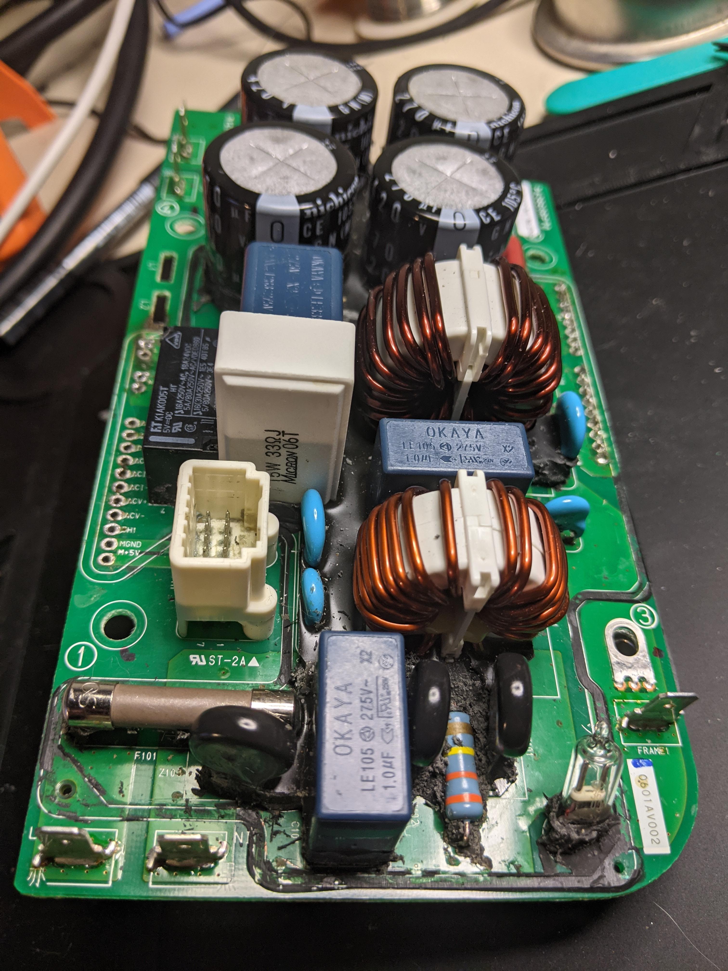
I spent a long time removing the bulk of the silicone potting from the top of the AC input board - not a hard job but requires care and concentration. This didn't reveal any blackened or cracking components, but it did show an interesting feature in the form of labelled connections down to the module below.
OaZ5wPk.jpg

On one edge the connections are labelled (with my guesses for function alongside)
L (two, next to each other and common) - AC input live
N (two, next to each other, and common) - AC input neutral
ACIN - AC available signal back to controller card?
IOG ground for I/O?
PWM
ACT
ACI+ AC current sense positive
ACI- AC current sense negative
ACV+ AC voltage sense positive
ACV- AC voltage sense negative
TH1
MGND logic ground
M+5V 5V supply from controller board
The non mains connections map directly to 11 of the 12 pins in the connector running to the control board. The remaining pin goes to the AC switch relay coil - and the other side of the coil is common with the M+5V.
On the other edge there are two groups of terminals labelled P (x 8) and N (x 9) - presumably positive and negative DC outputs.

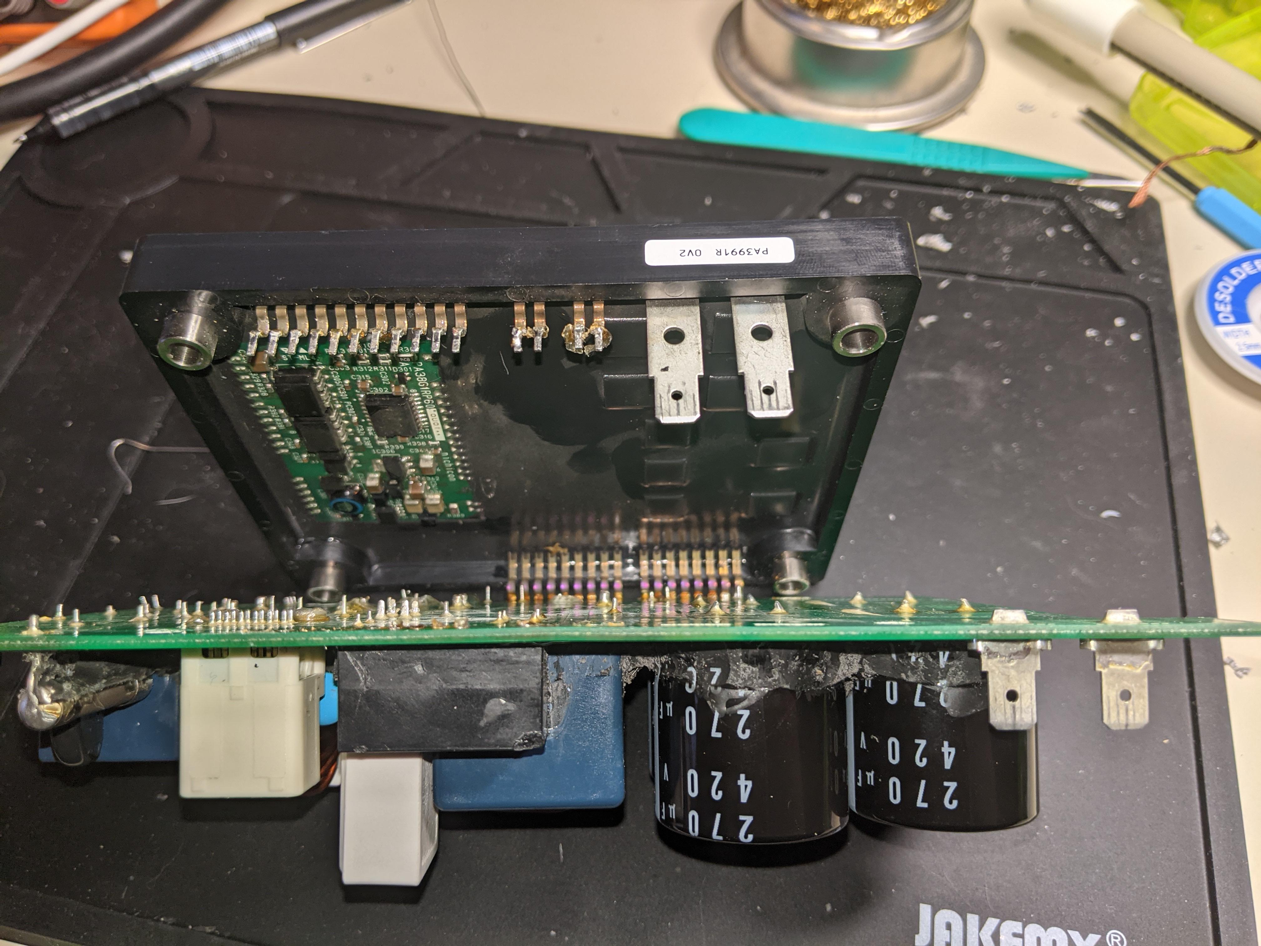
Next task was to desolder the top board from the base. This was a painful process, and so far I've only disconnected one side and gently bent the module open. There's another board with optoisolators and other circuitry sitting on top of the hard potting compound which contains the rectifiers etc.
4y8lg9F.jpg

Getting the module half open allowed me to check some more components on the top board, and this was where I found an actual problem. There is a single 33 ohm 15W wirewound resistor which bypasses the relay contacts (this is a little different from the later circuit) and it has failed open circuit. This resistor failing would give the symptoms I am seeing as no mains would ever make it down to the lower board to be sensed, though I'm a little concerned as to what made it fail. When the fault originally occurred (during charging) the earth leakage breaker on the power supply to the car also tripped, though it could be reset and has given no trouble since.

The resistor failing also explains why I saw no voltage on the fuse - wasn't a mistake after all. I was probing using a single multimeter probe with the other probe grounded to the chassis. The live feed must actually be on the N terminal (L/N swap), and because the resistor is open circuit no voltage ever made it to the fuse for me to measure.

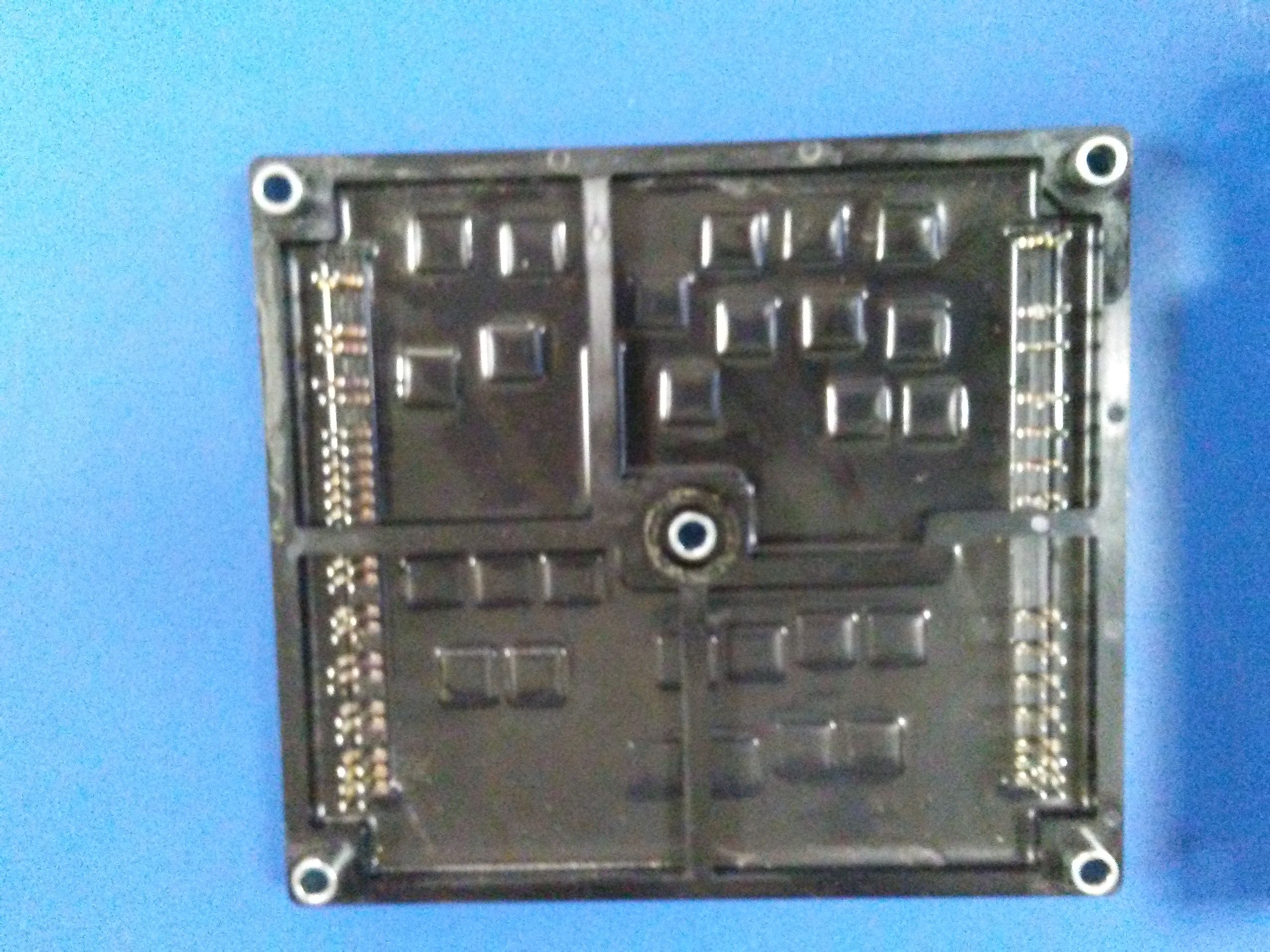
Here's a closer look at the underlying board.
jikS1We.jpg


So, has been a good weekend. I'll get some beefier soldering equipment to desolder the second edge - all those commoned terminals are like a huge heatsink - source a spare resistor, and I have a lot of writing up and circuit drawing to do.
 
kiev said:
@Phil, can you check to see if there is voltage on any the big electrolytic caps on the control board. i think there should be a 12V line to the OBC that is always powered up, and it will create a 5V supply on the board. Not sure if it is filtered and held up by one of the caps, but you should be able to find it on the board. Any of the little 5 or 6 pin ICs are voltage regulator chips. e.g. IC710
Good checks there with the troubleshooting to bypass the CHGP and get the EVECU to come alive. The DTC is related to a lack of CAN buss signal. But if there is a missing low voltage supply on the control board, then some of the interface and CAN chips may not be getting powered up, or the microcontroller chip is not powered up either. If you can read the part numbers of the ICs and make a listing we could compare to the 2012 version.

What is that little burn-looking spot in the lower left corner of the AC input board?

You would need to measure between the L and N tabs to read any mains AC voltage, measuring across the fuse both sides are at the same voltage so there will be no reading.
[/quote]

I'm sure I found 5V available in a previous check - also the processor coming up gives me a good feeling that we have supplies. I suspect the CAN error would have been caused when I was doing charge start power ups without the controller card connected. However, will do another power up test and confirm.

I could see no burn marks on any components. Are you referring to the neon spark arrestor (SA in the diagram below) that's protruding through the potting there?

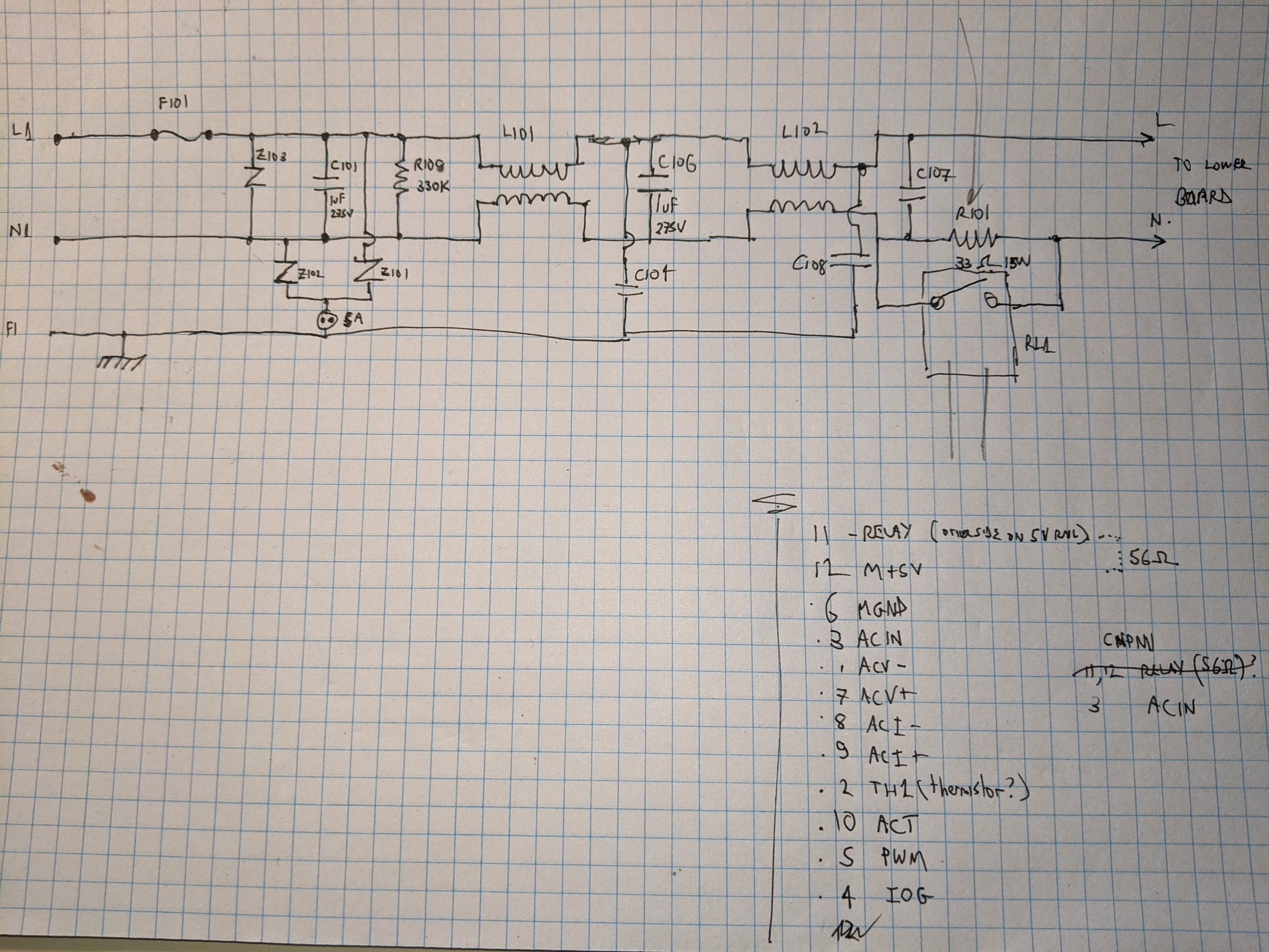
Here's an early draft of the mains input circuitry - as far as I've gotten. I think there are a couple of capacitors between live and frame and neutral and frame near the right hand side that I still have to add, but is gives you a rough idea of what I'm seeing. Pin numbers at lower right are for the connector CMPM1 which goes up to the controller board. R101 is the open circuit resistor.
lv7kYwt.jpg
 
Good catch to find that blown resistor. Is there a part number anywhere on it, it may be one with an internal fuse such as used on the 2012 version.

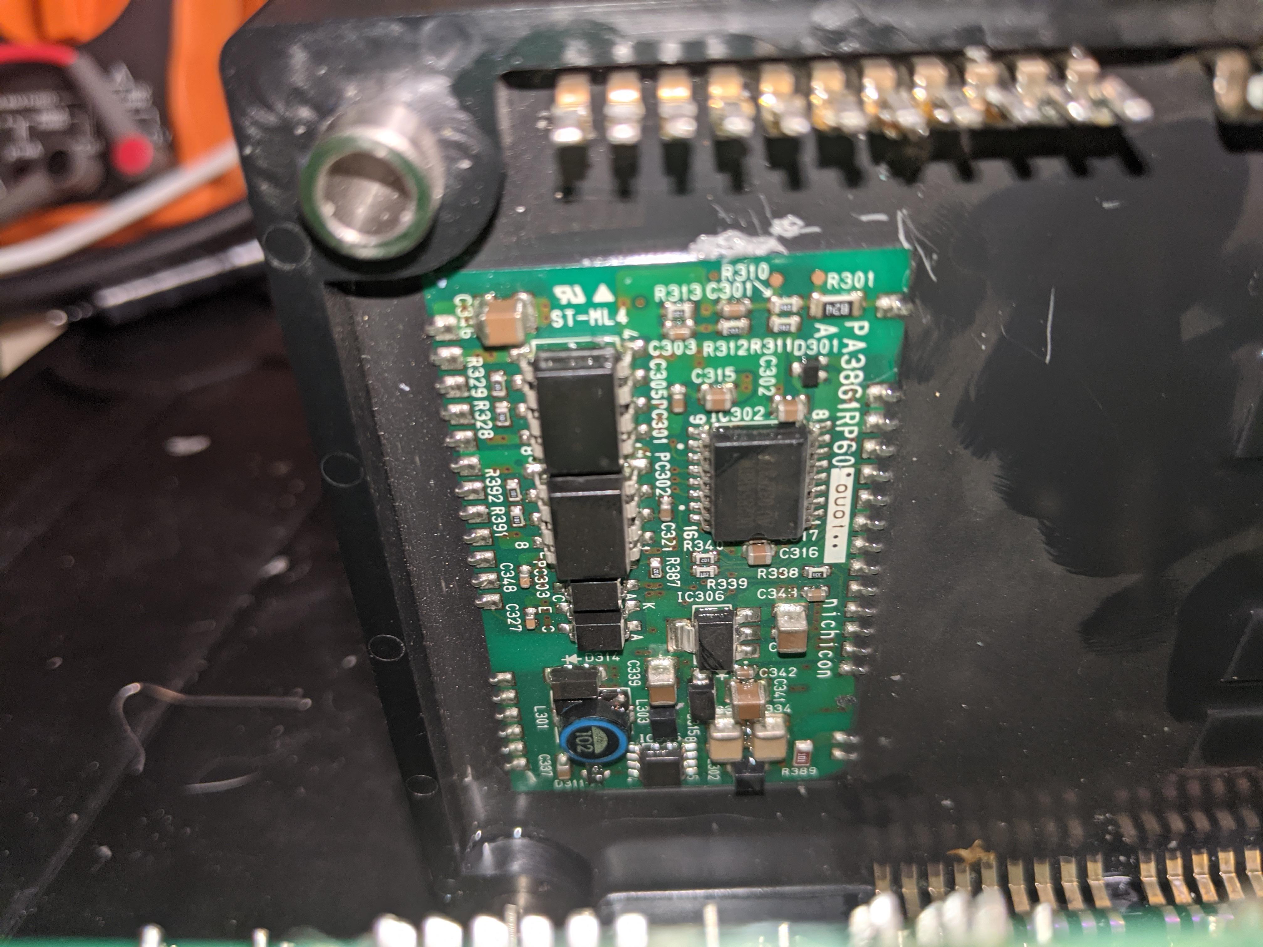
The IC302 on the little underboard, is it a UC28xx? That is the PFC controller chip IC312 on the underside of the power board for 2012.[edit: UC2854]

Chances are good that only the resistor is blown, but for some reason the AC relay did not come ON putting the full AC across it. Maybe the AC relay contacts are frosted over.

You could check the diode drops on that waffle plate as it is without removing all those PIA solder joints if desired. Hopefully it is intact and not affected, that is typically what is seen in the later versions. AC input failure is usually either Ceramic resistors, filter caps or relay.
 
kiev said:
Good catch to find that blown resistor. Is there a part number anywhere on it, it may be one with an internal fuse such as used on the 2012 version.

The IC302 on the little underboard, is it a UC2845? That is the PFC controller chip IC312 on the underside of the power board for 2012.

Chances are good that only the resistor is blown, but for some reason the AC relay did not come ON putting the full AC across it. Maybe the AC relay contacts are frosted over.

You could check the diode drops on that waffle plate as it is without removing all those PIA solder joints if desired. Hopefully it is intact and not affected, that is typically what is seen in the later versions. AC input failure is usually either Ceramic resistors, filter caps or relay.

You can see the resistor in the end on board photo above. It is the white 'tombstone', and labelled "15W 33(ohm)J Micron 06T". As far as I can make out from the Micron catalogue it is an MNS15N330J - which isn't one of the fused varieties. It has four terminals - two per side - presumably to handle current.

IC302 is marked UC2854BDW. That is 54 and not 45.

Good thought on the relay, I shall check it out and order a spare anyway.
 
Back
Top