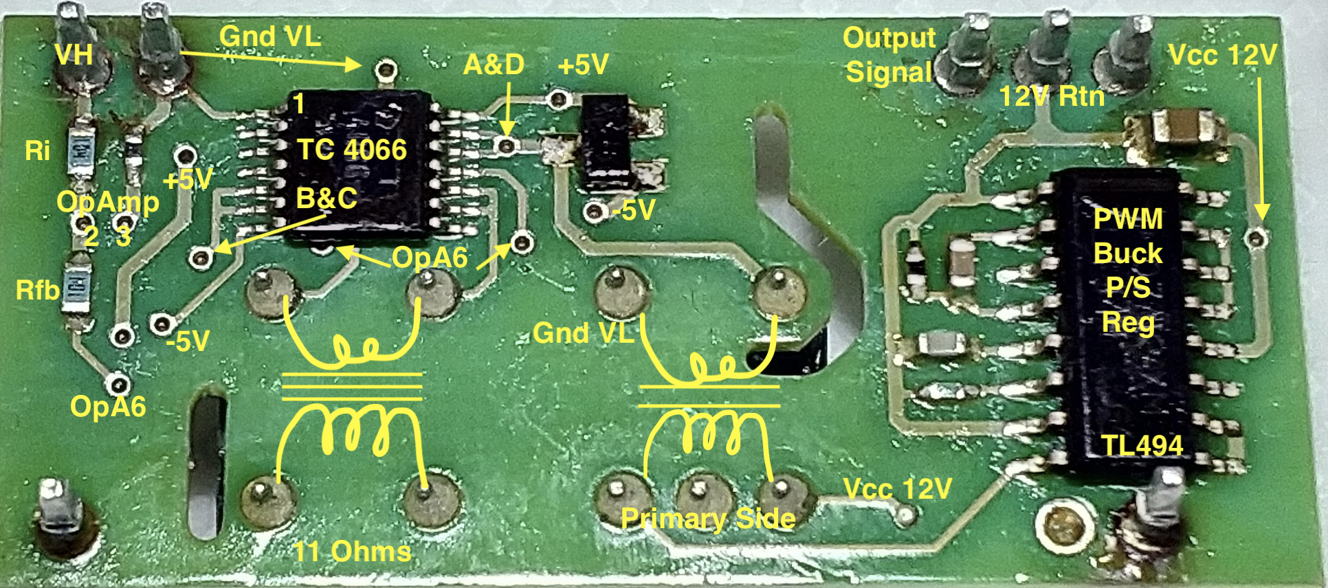
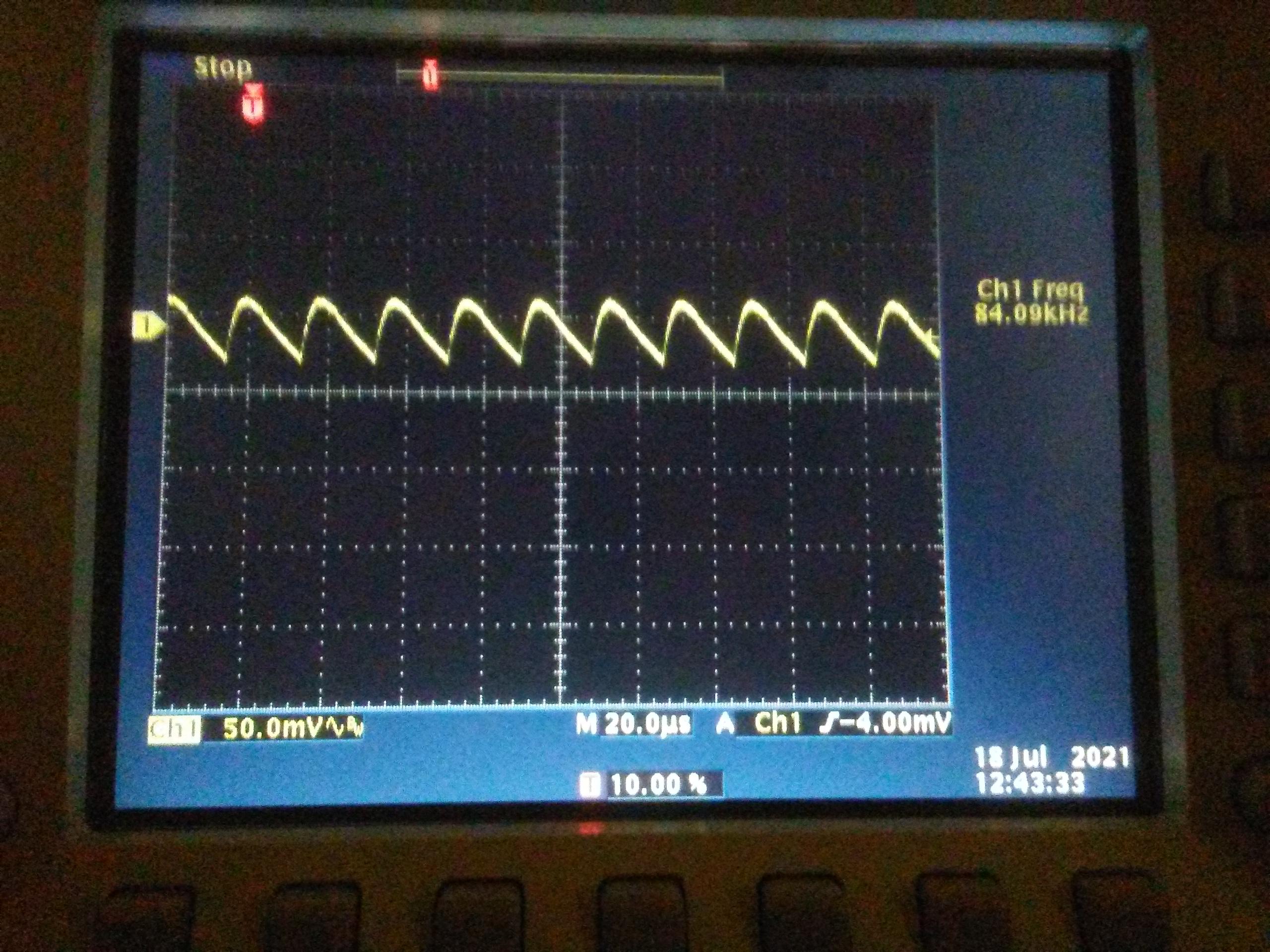
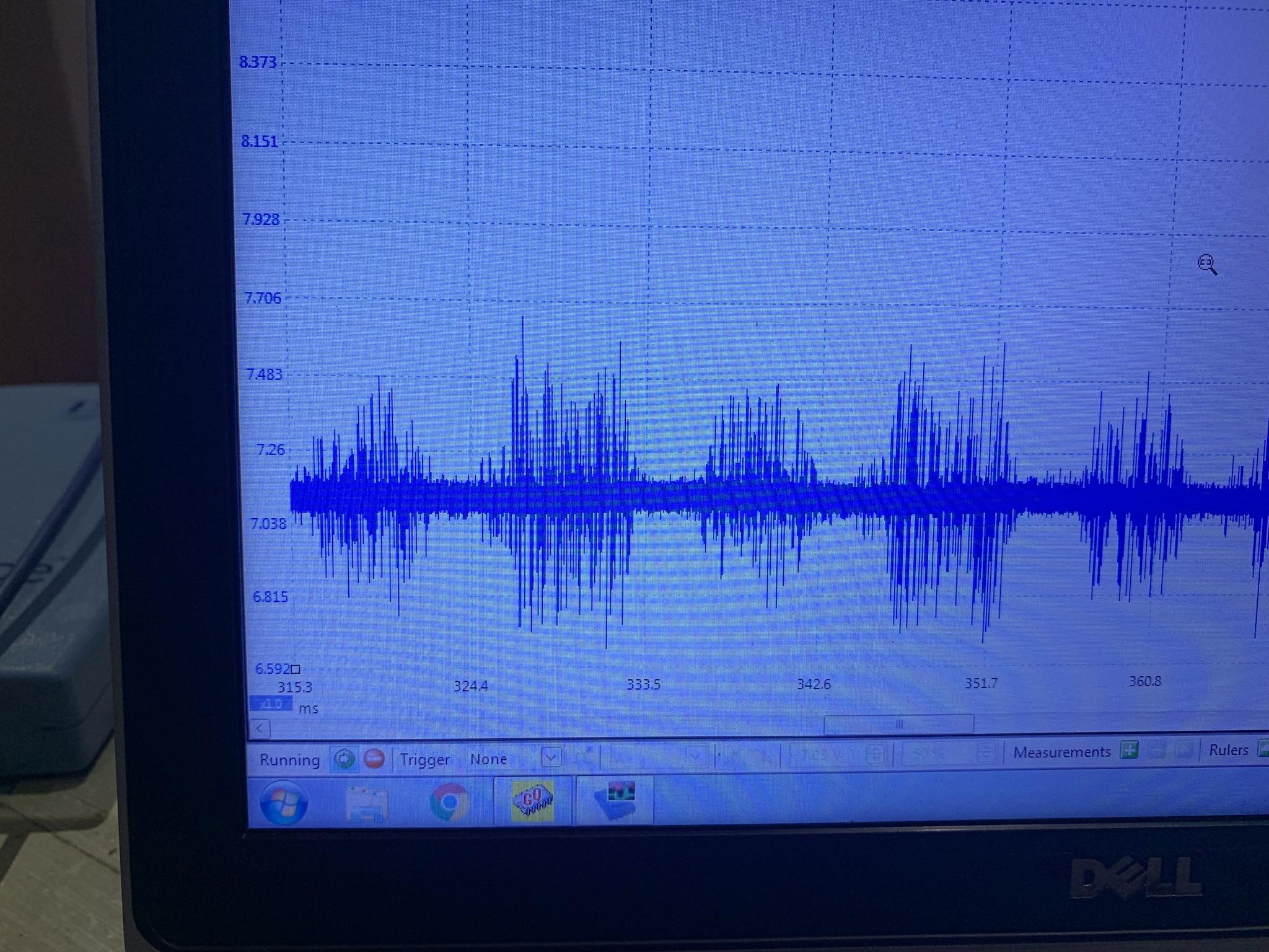
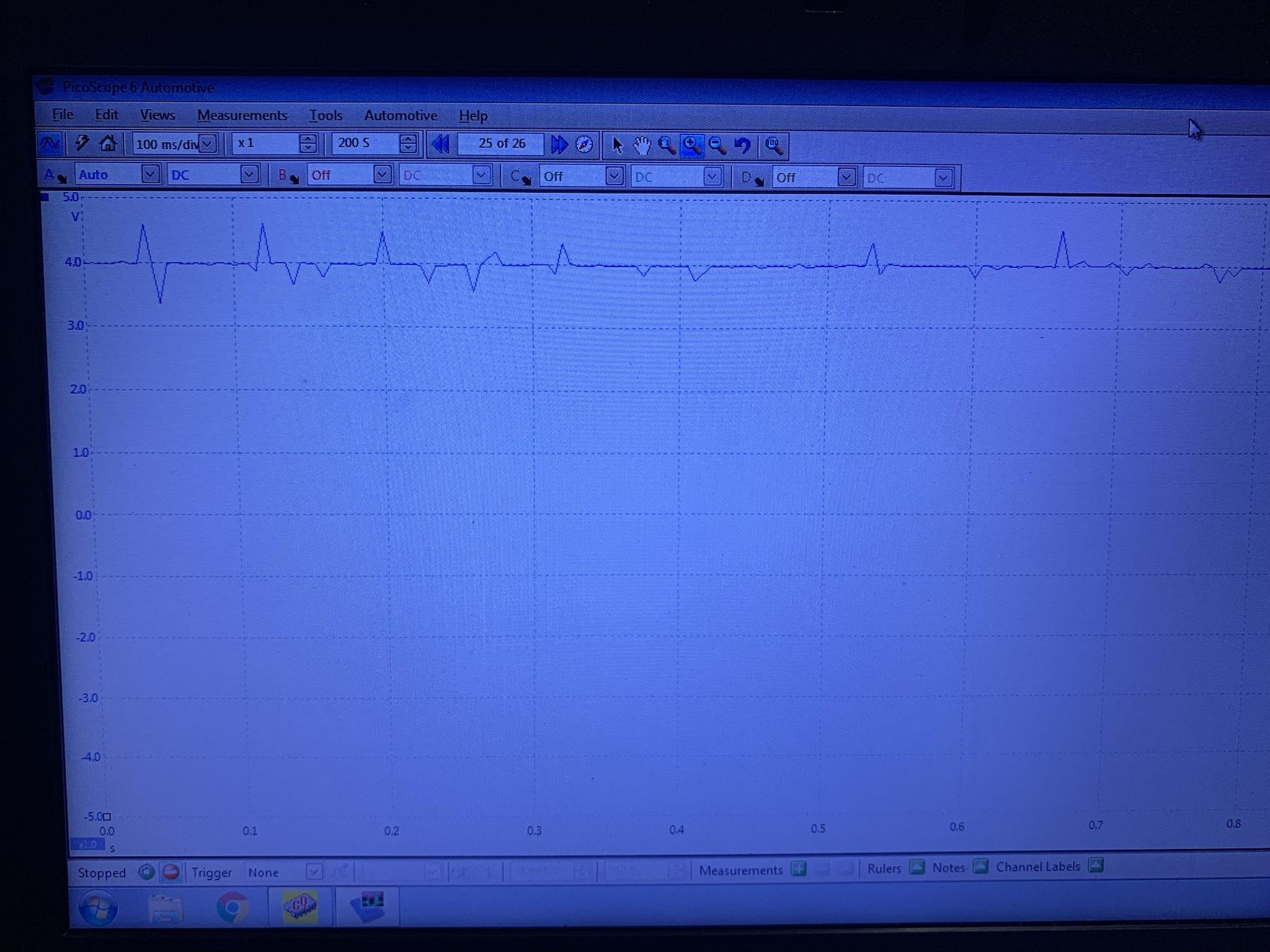
With 15.0VDC for my supply, i measured +7.38 with multimeter for the V+ low voltage supply, and used the scope to look at the ac ripple on top of this, which looks to be about 50mV.
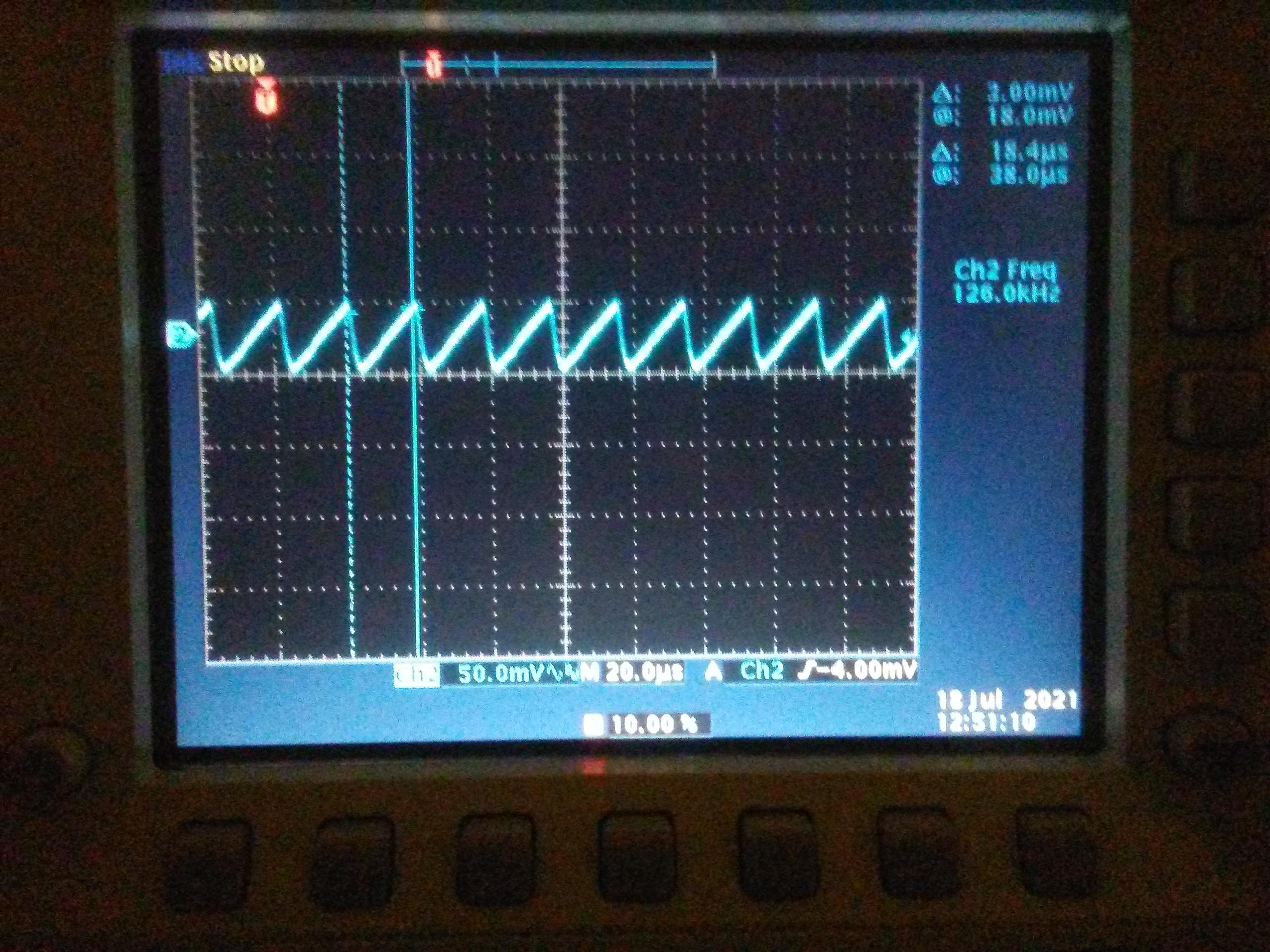
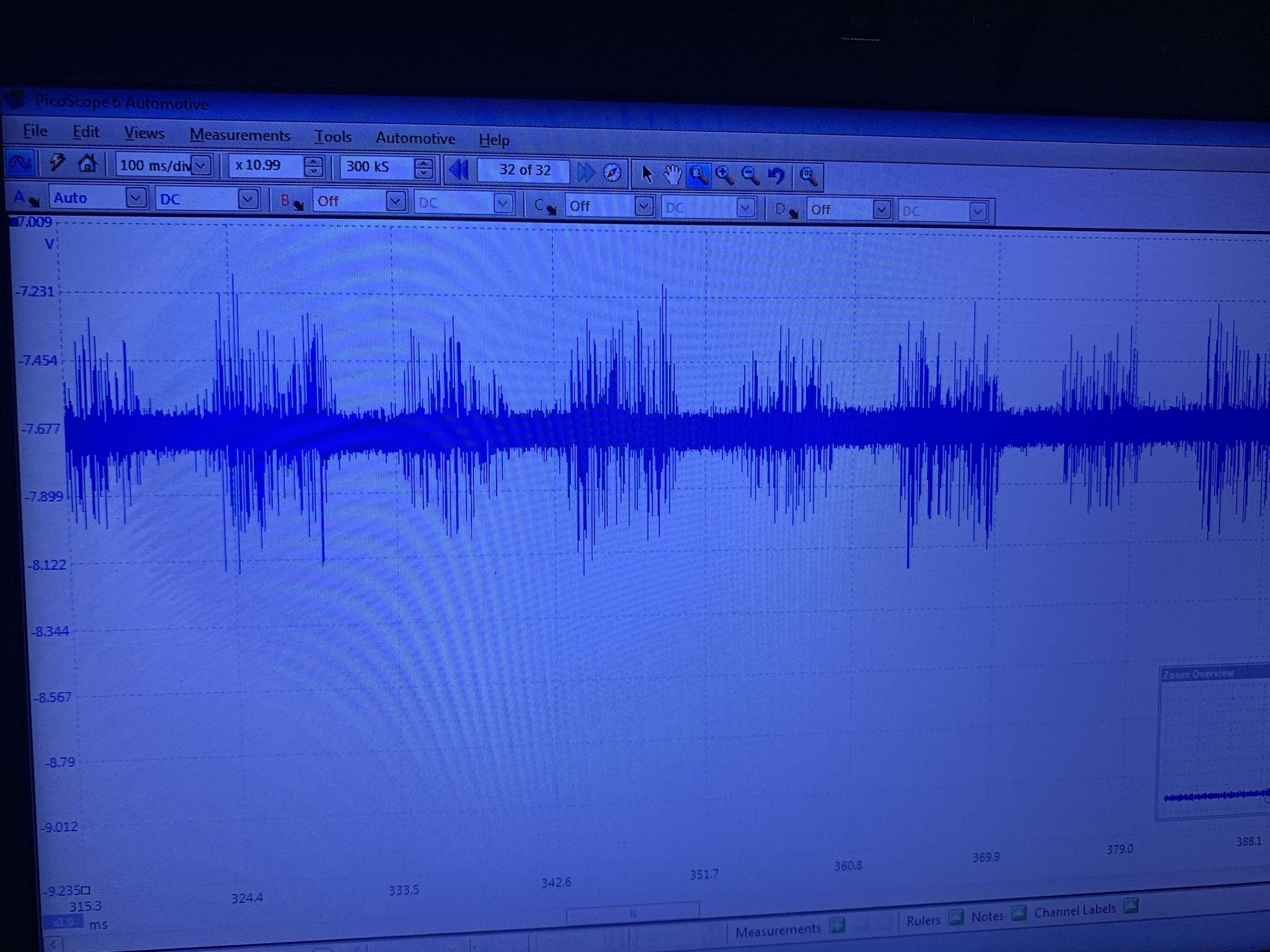
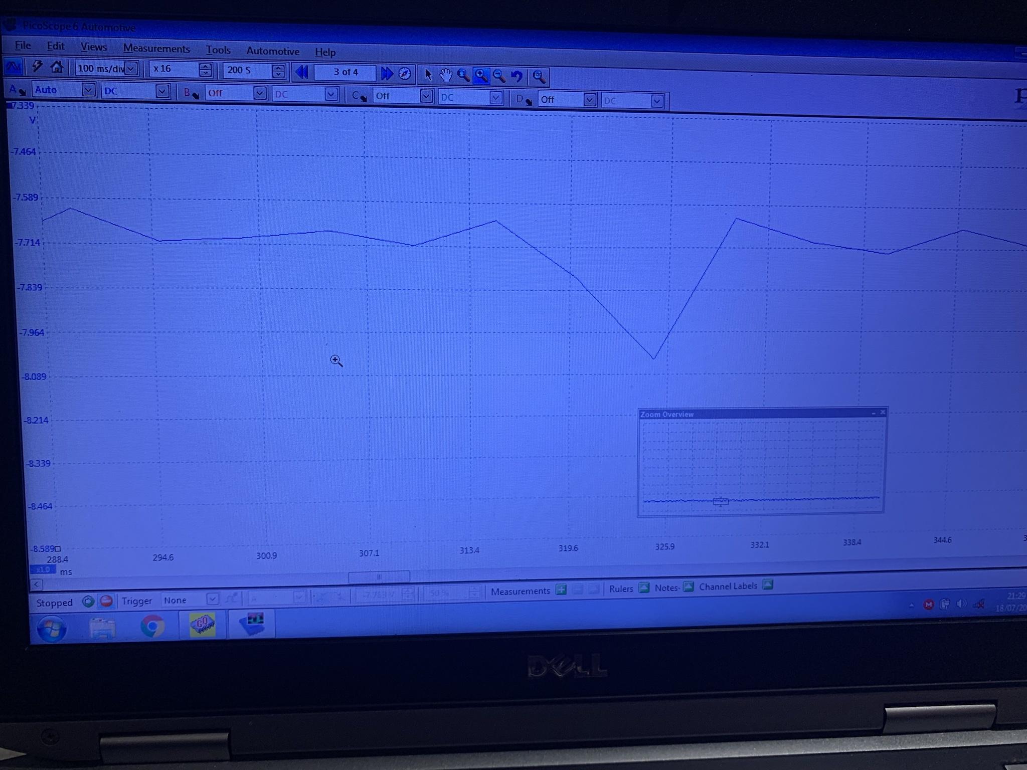
i measure -7.49 using a meter for the V- low voltage supply, and also looked at the ripple, about the same 50mV but it has a really sharp edge.
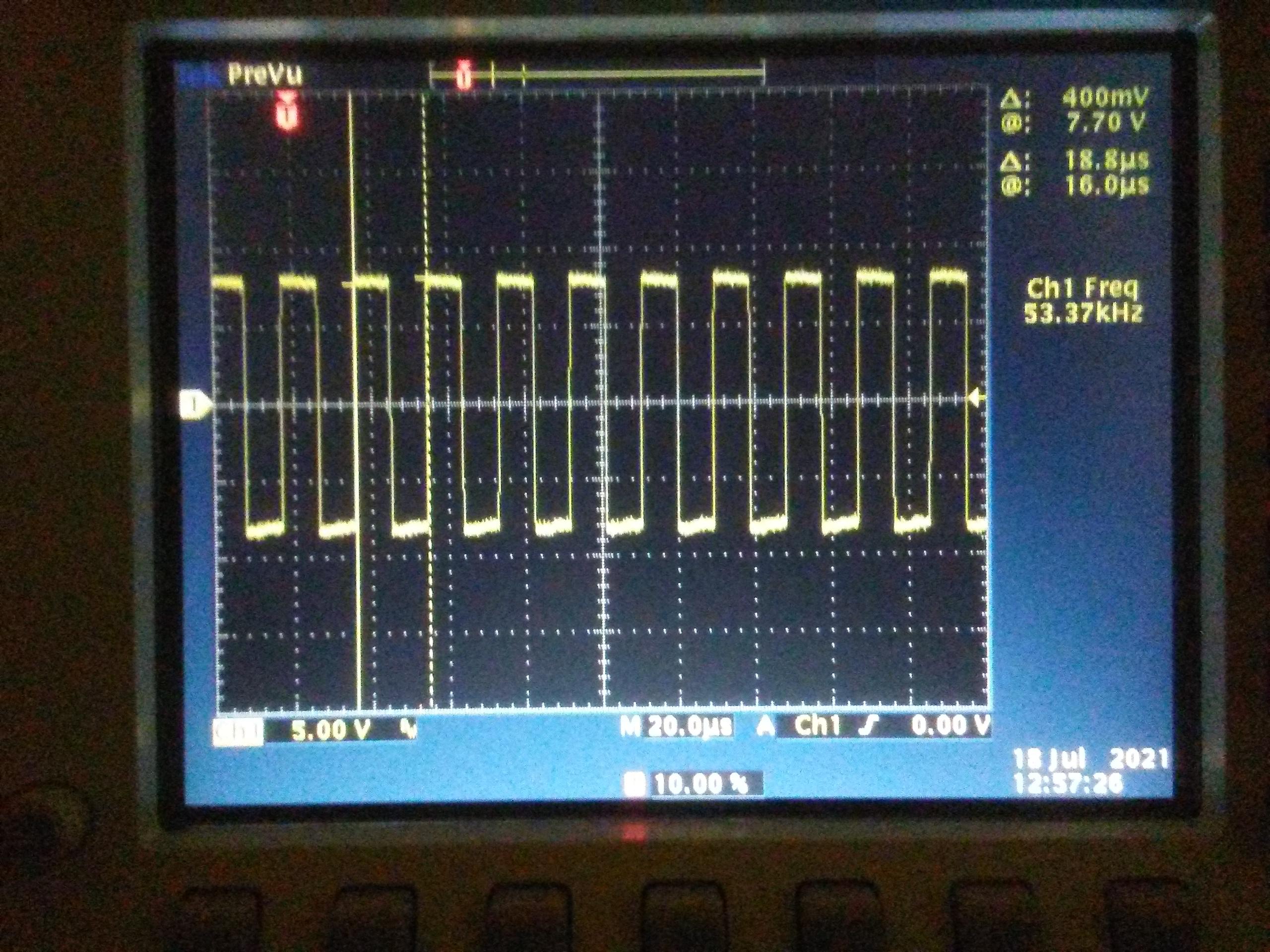
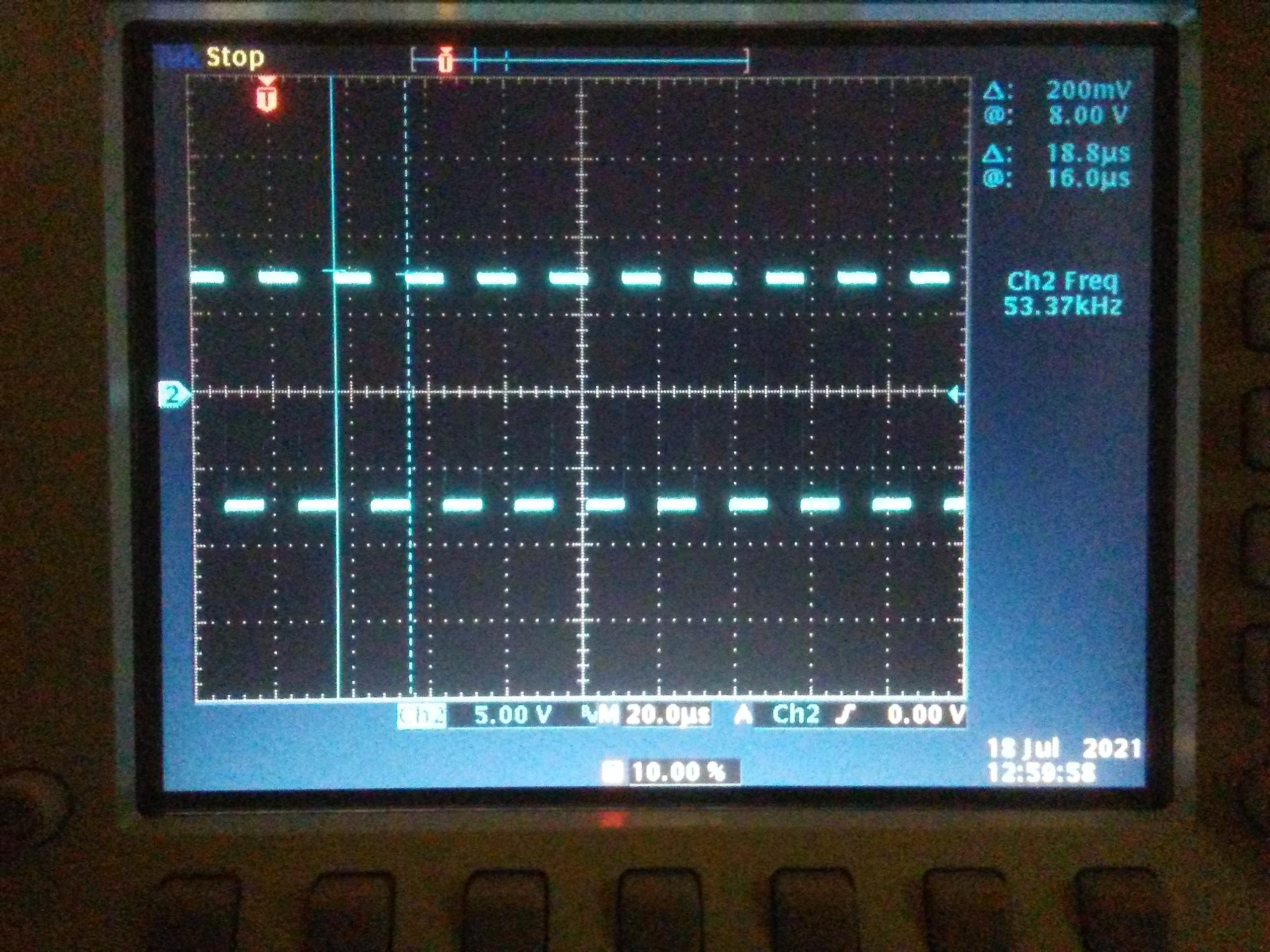
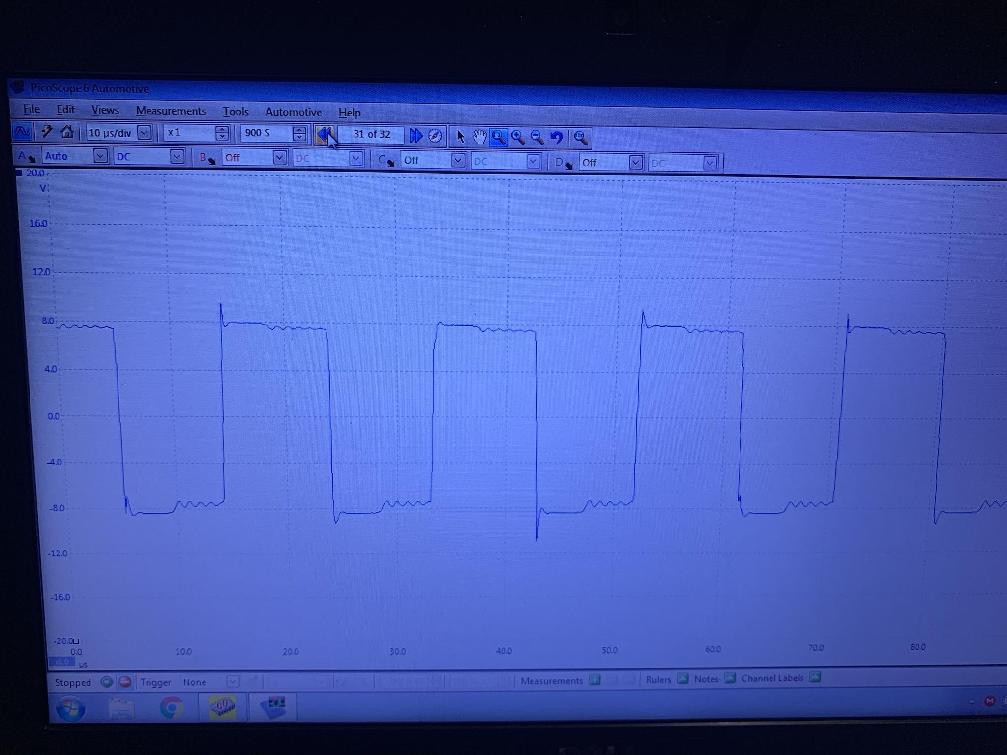
Using the scope i looked at the A&D Switch Control signal, this is also the output on the secondary side of the power transformer.
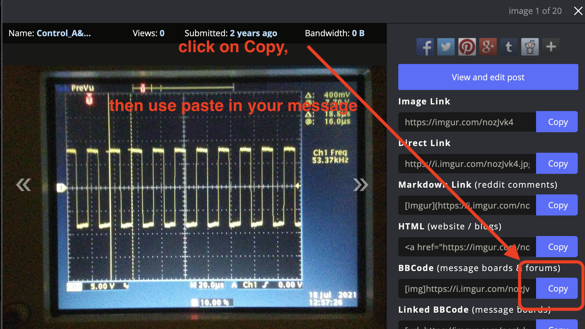
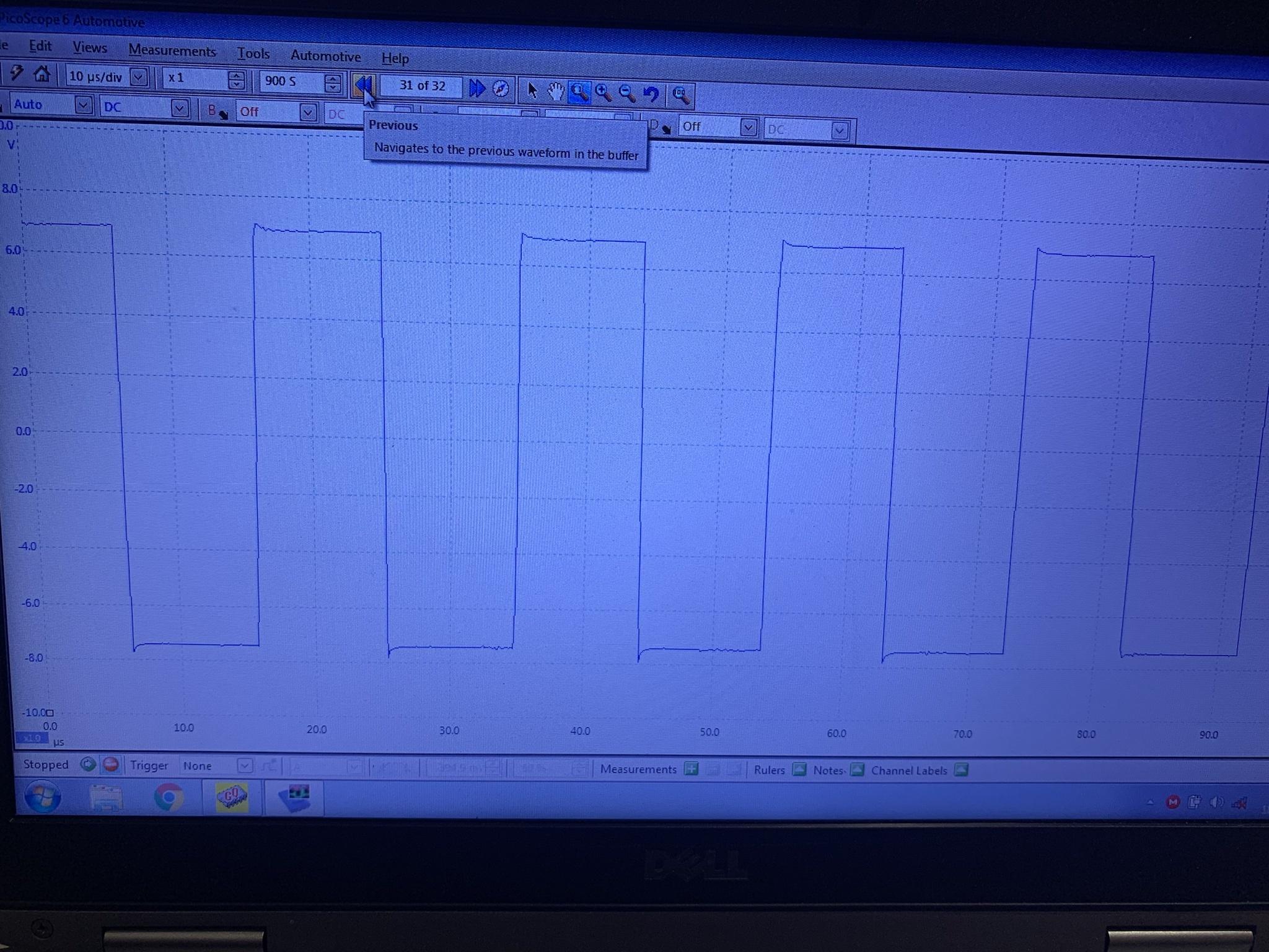
and the B&C side Switch Control signal, which is the output of the single inverter gate chip.
The control signals are switching at the same frequency of the PWM, ~55kHz. The scope frequency measurement on the ripple seems to be at a higher frequency, but just looking at the trace it is the same as the control signals. Not sure why the scope is confused.
i think these are the signals that must be examined to troubleshoot this board, or at least these would be useful to determine whether the board is operating properly or has a fault.


