[ The P1A15 Troubleshooting Thread ] No READY. P1A15 error. Condenser charge timeout.

Mitsubishi i-MiEV Forum

Help Support Mitsubishi i-MiEV Forum:

This site may earn a commission from merchant affiliate links, including eBay, Amazon, and others.
Yes the 347 is the peak hold, which is not far off of 348 battery voltage

The resistors on both boards measure exactly

The 3.654 was peak hold also

how about if I put the spare board in without the hybrid board and measure voltage at vl and vh or does it need the board as a load?
 
There [will be] a slight load on the VH-VL [due to the input resistor to the op amp].

i'm hoping you find a bad ceramic cap causing all this. Did you see my edit on the post above, it may have cross with your post.

Looking back at your pictures i see that you didn't mark those supply caps as being replaced on the old board either. i'm sure i recommended to replace all the ceramic caps very early on. From page 15
But the easiest thing may be to just replace the caps, all the caps involved in this circuit both on the control board and on the hybrid board
3PG5svg.jpeg


i'll be back online later tonight or in the morning.
 
I have read through your last few posts kenny and what I am trying to prove is the suspect loss of input voltage on my new board.

So with the old board refitted and the hybrid board on I get 3.65v at vl vh

With the hybrid board removed I get 3.894 at vl vh

Is the hybrid board meant to be such a load to pull down the voltage that far.

I’ll leave you in peace for a while!
 
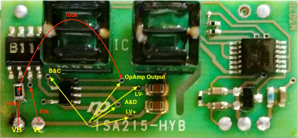
The vias in the top side are like test points that can be used to check the health of the board. Resistors on the bottom can be checked as shown in red. Voltages can be checked as shown in yellow.
OTZqe2y.jpg


The two filter caps on the LV supplies: the 700nF measured with smart tweezers may be an error. At 55kHz that value is like a 4 Ohm impedance, so it would be pulling down the supply. We need to get a measurement off the board to really know what value to use.

That's all i got for tonight.
 
Morning kenny,

A very interesting bit of reading on your last two posts, I had to read it all twice to digest it.

I had replaced the op amp on the original board with the one specified but it never worked even though it was new but has the over voltage degraded other components on the board?

I am getting exactly the same symptoms and test measurements with both boards but the proof of the pudding is that the hybrid board is pulling my input voltage down on both boards when fitted what ever I do to them.

As you know I have replaced pretty well all of the components on the original hybrid board and all I have done is make the issue slightly worse!

We know that the car is a runner as when I modified the board with the temporary resistor and the fault lies with the real and simulated voltage being different causing no READY light.

So where do we go from here today? Do you want me to test all of those points on the new hybrid board and report back?

I don’t want to disturb the new hybrid board too much but can remove the caps as requested to check properly, my cap meter has packed up but a new one is on the way today.

I am concerned now as if the op amp is not suitable for purpose then we are going around in circles and quite plainly until we see the same voltage on vl vh as when the board is on or off there is nothing more we can do?
 
I am just looking at the RS components website

There are thousands of op amps!

There are 2110 8 pin surface mount

How do we round down any suitable, this is a little over my head but willing to learn….
 
The two filter caps are 1uf

The three resistances you wanted checked are perfect

Next tests

Input 4.00v on vl vh with hybrid board still fitted to main board

Voltage across vl too:

B and c 0.65v fluctuating slightly

Op amp output 1.112v

Lv- 373mv

A and d 0.003mv

Lv+ 0.789v


These results are with no 12v supply? Was a 12v supply required to do this test?
 
boothegermanshepherd said:
There are thousands of op amps!
Sure.

How do we round down any suitable, this is a little over my head but willing to learn….
I usually find Digi-key's parameteric search to be the best, but in this case, not so much. I specified one channel, a few package options that include 8-SOIC. Alas, input range can't be specified, and even rail voltages are stupid and unusable.

I finally stumbled on this one; its input range is wider than Vcc! Note: look at the specs for the 7612, not the 7611 which shares the same datasheet.

https://www.mouser.com/ProductDetail/Renesas-Intersil/ICL7612DCBAZ-T?qs=9fLuogzTs8LgICyq7GcQig==

There is something about programmable quiescent current; you'd have to chase up what if anything connects to pins 8. 1, and 5. At least the main pins are very standard: + and - inputs, output, V+ and V-.

Digi-key had this one, but with a minimum order quantity of 401. Mouser will sell you just one. But maybe get two and potentially fix both boards? As usual, the part itself is cheap compared to shipping.
 
Hi

Which one in this selection there seems to be two of the same but different makes?

https://uk.rs-online.com/mobile/search.html?searchTerm=ICL7612DCBAZ

Obviously I only want 5! Or a small quantity.

Thanks

Edit….


ICL7611DCBAZ Intersil, Op Amp, 1.4MHz, 3 → 15 V, 8-Pin SOIC


This is the only one available from the store I use!?

The rest are back order till 2022!
 
The Nippon Pulse datasheet for the hybrid board indicates that it is good up to +5V on the input with +5V output, with a supply voltage of +15VDC. So everywhere that i was using "12V" for supply should be 15V, and Boo verified that with measurement in the car.

With 15v supply then the PWM could be swinging +/- 7.5 thru the power transformer primary; if it is a 1:1 secondary, then the A&D signal could also be +/- 7.5, and the LV supplies would be a diode drop below that, call it +/- 6.8. Subtract the 1.5V Max Input O/V, and that says this all should work at up to 5.3V on the VH input pin.

In our cars the VH will never go over 4.15V so it would seem always within range. But numerous guys have reported their LV supply voltages at less than 6.8V, and as being unequal such as one side loaded down more than the other, and down low enough that the 1.5V Max on the input could come into play.
 
boothegermanshepherd said:
...
These results are with no 12v supply? Was a 12v supply required to do this test?

Thanks for the measurements, yes the board has to be powered in order to read any voltages, and unpowered to read resistances. With 15V if possible since that is the rated spec for the hybrid board.
 
The Op Amp may not be the root cause, it may just be doing its O/V protection as it was designed to do.

A common issue seems to be the degradation of the LV supply voltages, which points back to the TL494 chip and its associated passive components. Or to a degraded power transformer.
 
I have replaced the tl494 but none of the components around it

My original board is showing a vast difference now between input and output nearly half a volt. This could be as some replacement components may not have been the correct value or that the board is degrading with so much heat applied?

My concern goes back to the input voltage on vl vh dropping when the board is connected? Could tl494 cause this issue?

Edit

I will do the tests again with voltage connected to pins 4 and 5 but I don’t have another variable supply only 12v
 
The NP datasheet indicates supply voltage Min 14V, Max 16V. It would not be very much current draw, could you use some battery cells to create a series string or add it to the 12 to get up to 15V?
 
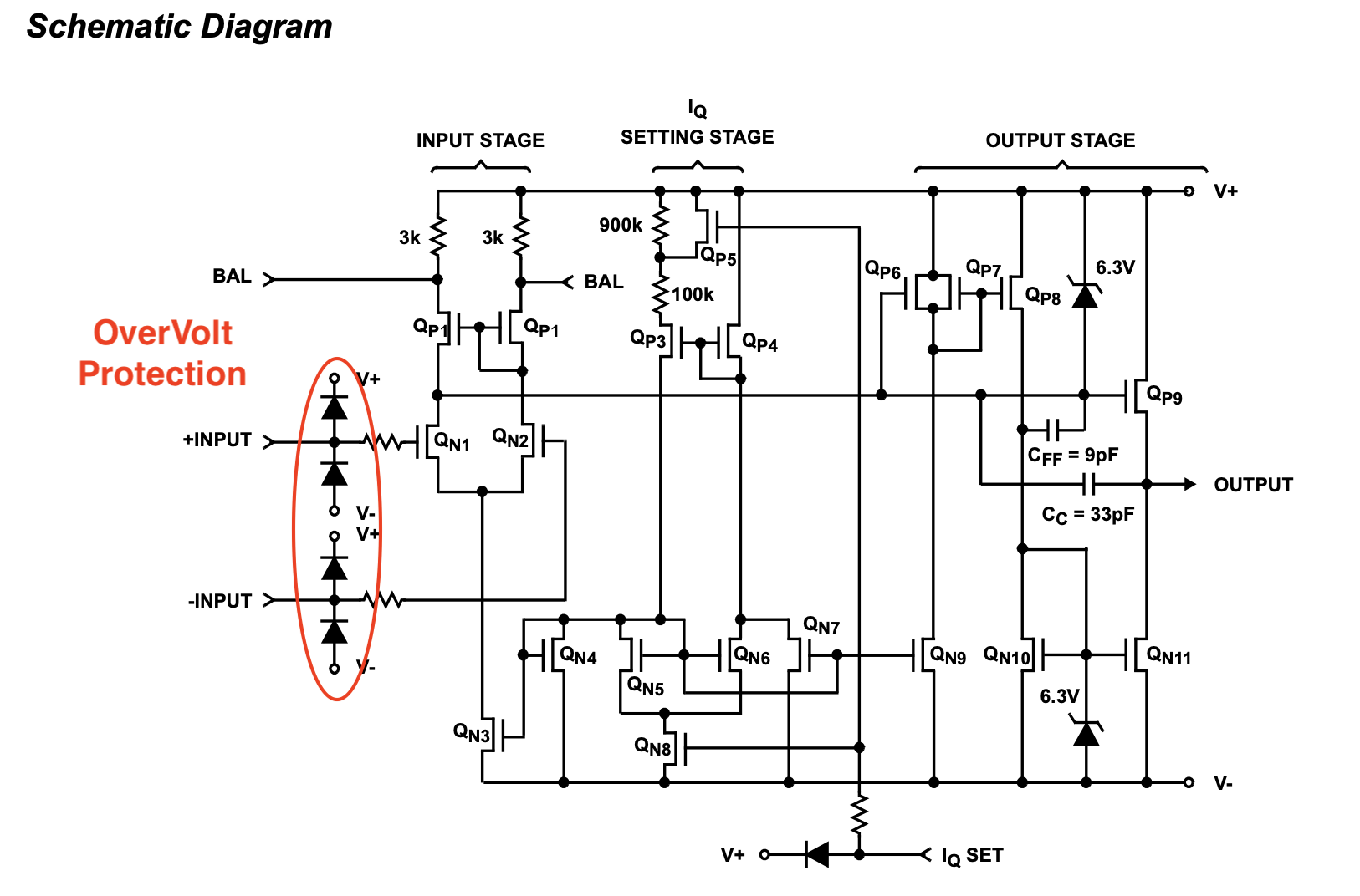
Here is the internal schematic showing the overvolt protection for this chip. The AD chip likely has something similar like Zener diodes that cuts the input at 1.5V below the rails, but they didn't share it on their ds.
TTyVO2n.png


The only limiting factor i can see is possibly the output current. The op amp output is used to drive the winding of the signal transformer which is only 11 Ohms DCR. The switching frequency will be around 55kHz so the coil impedance will come into play to reduce the peak current. The AD chip can drive 15mA, but i don't see a rating for the ICL.

i'm hesitant to recommend the ICL chip, too quirky with the IQ and lack of output current drive rating, but it's worth a test.

The problem still needs troubleshooting to establish the culprit.
 
That was all over my head your last post!

I have ordered a handful of op amps to test

I will do the other test, I have emailed you a picture of a supply.

EDIT

I have ordered:


Standard Items Ordered Reference: 163665140
ICL7611DCBAZ Renesas Electronics, Op Amp, 1.4MHz, 3 → 15 V, 8-Pin SOIC
Stock no.:496-717
Qty:5
 
Back
Top