And now my I will not charge!!

Mitsubishi i-MiEV Forum

Help Support Mitsubishi i-MiEV Forum:

This site may earn a commission from merchant affiliate links, including eBay, Amazon, and others.

1pk

Well-known member
Joined
Jul 10, 2014
Messages
93
Location
Chemainus, BC
I plugged in at home today after work and it clicked and whirred, but then my evse clicked off and it would not charge. After several attempts I gave up and tried my portable unit with the same result. Now I sit at the closest DCFC getting some electrons for tomorrow’s commute and I am thankful this is working!

It starts, and drives, there are no warning lights on the dash. I could use a little guidance on what to check. I am not an electronics guy but I follow directions well so I hope I can sort out the problem with a little help from you smart folks on this forum.

My car has 132k km and the 12v is new as of last October. I tried to check the voltage but my voltmeter seems to be hooped. I will borrow one tomorrow and test to it.

Last weekend I noted some unusual charging behavior. I needed a small top up to get home so I stopped at an L2. In 18 min the car charged 500wh. I tried another charger (flo is the provider) and that one was the same. Off to the next one and that worked for 5 minutes and shut off. That was enough to get me barely to a DCfC which worked fine.

That all happened on Sunday and everything has been fine until tonight.

Where do I start?

Thanks

Pete
 
Your 12V Aux battery appears in great shape.

Since your car charges with DCQC level 3, and is intermittent with the level 1 or 2 EVSE, then it points to an issue with the path using the onboard charger. The pack is likely okay since it does charge properly with Chademo.

The biggest source of intermittent issues is dirty or corroded terminals in a connector.

Inspect the EVSE handle contacts and those on the car's charging port with a bright flashlight, then clean any dirt, debris or insect parts out of the sockets using a wooden toothpick, cotton swab and rubbing alcohol. If there is any blue or green colored deposits then use vinegar to clean those off.

Hopefully that will get it working again--let us know what you find in those sockets.
 
Ok, cleaned the charge port with q-tips.

This is what it looked like before I cleaned it.


https://imgur.com/a/LFkjiVO

Unfortunately there was no change in the charging behaviour.

I tested it on a public charger after work. This particular charger really wanted to work so it kept restarting.

Here’s What canion displayed during the attempt
https://imgur.com/a/Nrr6cts

I appreciate the help. What do you think?

Pete
 
With a blown charger 20a output fuse, it’ll do the j1772 handshake and cycle the fan, then shut down. However, I think that fuse is shared with the DCDC input, so this chump is stumped. Some other charger failure?
 
I see the troubleshooting thread started. Looks like a lot of us are in need of help with this issue. I’m going to keep this thread going for my car. Hopefully it will help other folks who are at my level of knowledge.

I’ve dug into the rear compartment and taken some photos of the internals.

https://imgur.com/a/1E8FRTB

https://imgur.com/a/vrxwKz8

https://imgur.com/a/gifE8JM

https://imgur.com/a/x8nd5z3

https://imgur.com/a/s6A0eoE

So is the left box the inverter and the right one the MCU?

Which connections should I take apart to clean?

Are there any Spots that I can not touch for safety reasons?

Can I test that ceramic fuse?
 
The charger/converter(dc-to-dc) box is on the left, and the Motor Control Unit (MCU, aka inverter) is on the right.

As long as the key has been OFF for 10-20 minutes there should not be any high voltage in either box. There is a bleed-off resistor that will drain the HV from the capacitor.

The fuse can be checked with a meter on either the resistance(Ohms) or continuity(beeper) setting. Since your 12V is reading 14.4 while in READY mode, this indicates that the fuse is good, else the dc-dc converter would not be receiving any HV thru that fuse to do its job.

i use a vacuum cleaner and brush to get up all the road dust and debris before opening any covers.

You could remove the screws following the number sequence arrows of the top board inside the charger, along with the AC input screws and CAN buss connector to lay that board over toward the right, then inspect the bottom board for any residue or debris from blown components.
 
Great , thank you! I will have a look at removing that board. I was very careful to not get debris into the electronics.

I see there Is no gasket on the lid just a sealant. What type of sealant is It? I’ll need to get some.
 
The gray color of the sealant leads me to think it is an electronics grade RTV that doesn't off gas acid as it cures (non-corrosive). They are somewhat pricey but worth it for anything near electrical or electronic parts or boards. Less is better than more, a very thin bead is plenty.

But i haven't sealed mine back, just brushed off any dirt and bolted the cover back on--i'll probably be going back in there often and not worried about sealing until i'm done messing around in there...
 
So I opened up the inverter again and I couldn’t see anything obviously wrong.

Images of the circuit boards are below along with a closeup video scan. I wiggled all the spade connectors on the board but it didn’t change anything.

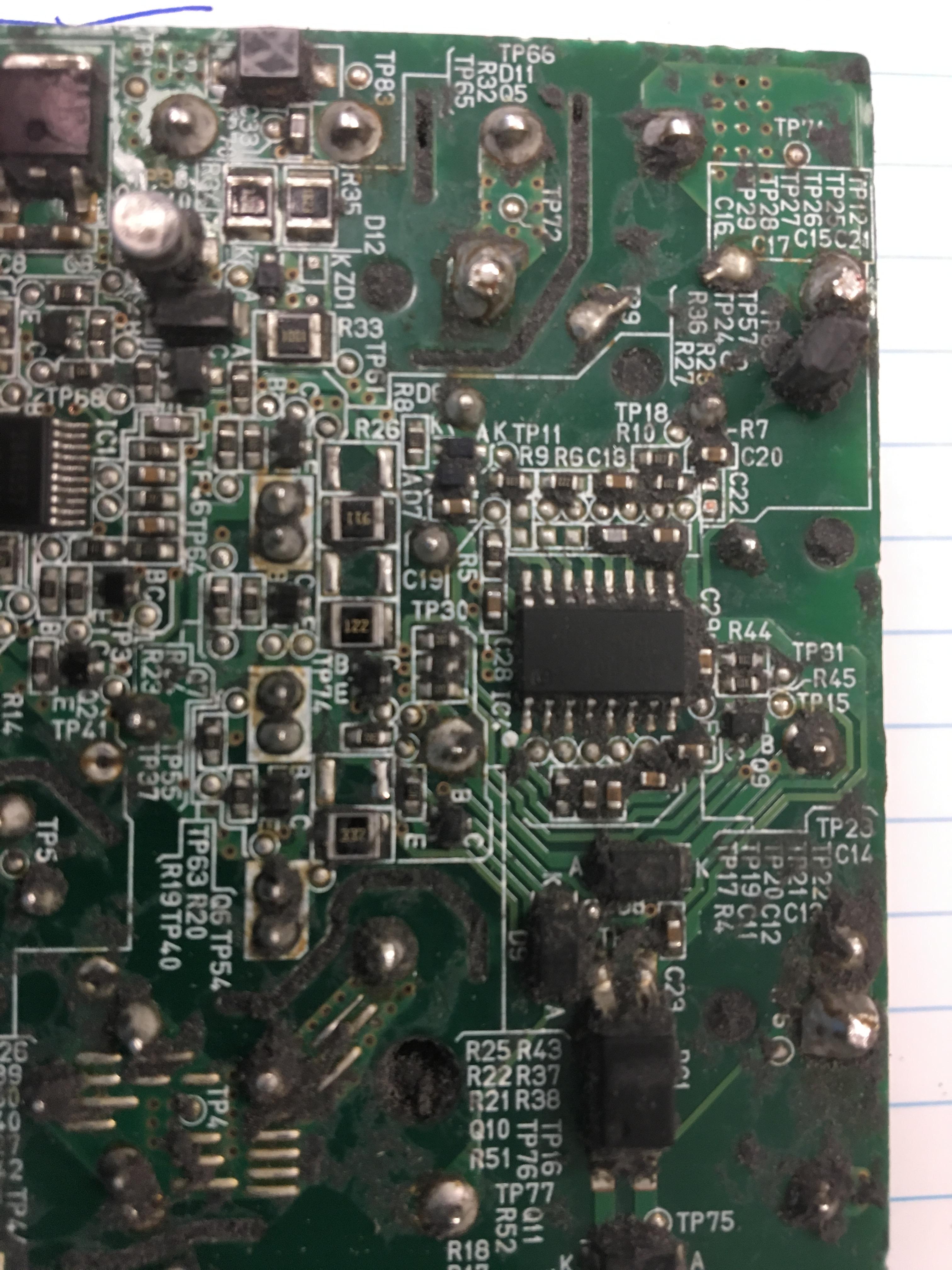
Bottom of the top board

https://imgur.com/a/w6eQjSW

Video of the bottom board looking for a problem.

https://imgur.com/a/IBSQkGt

Even though there are no warning lights, would it b helpful to take it in and check for error codes?
 
The video was a great idea.

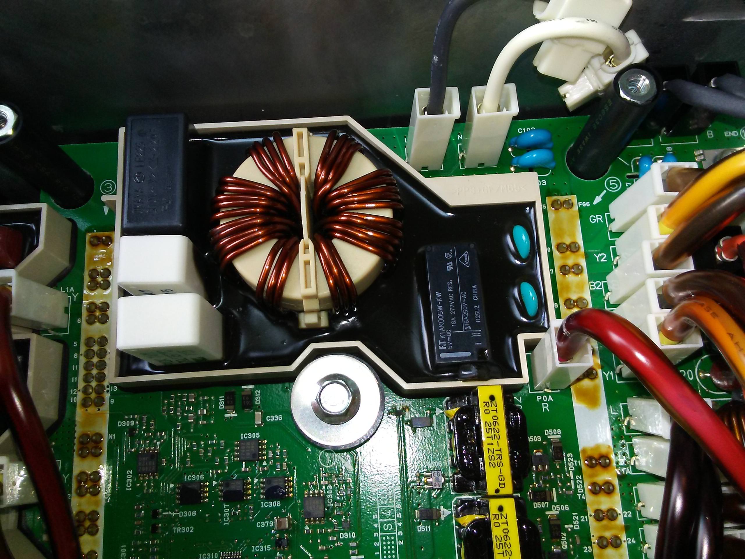
It looks like the big white ceramic resistor (left one of the pair) is cracked and has discoloration at 0:11 of the video.

There could be some stored DTC in the EV-ECU related to the charger, but it seems like the dash would show a trouble light. There are about 26 internal on-board charger trouble codes that get flagged up to the EV-ECU. i put a list of these and the EV-ECU DTCs in the troubleshooting thread.

Does the charging indicator lamp come on or blinkk when you try to charge?

When you plug in the level 1 EVSE, what color LEDs come on or blink? Does it appear normal or does the fault (red) led come on?

The iCarsoft i909 obdii scanner can read and clear DTCs, read CAN buss data, etc it is not as powerful as a MUT3 but it is a handy tool.
 
The charge light blinks when I plug in.

I’ll open it up again tonight and photograph that component more closely.


I’m really glad you saw that. I was quite disappointed when I couldn’t see anything wrong.

Thank you
 
And there is no error light when using l1. Again I’ll check the exact sequence of the lights this evening if that’s helpful.
 
So I finally got back into the inverter and that resistor is cracked

https://imgur.com/a/CL1X54H

The part # is obscured by the potting and it’s proximity to the 2nd resistor beside it.

So... any guesses as if this could be the cause of the charging problem or if it is a result of another problem?

And suggestions as to where to have this repaired?

Thanks
 
Yes it could be causing a no-charge situation if the resistor is cracked thru and causes an open-circuit condition.

My guess is that is in the AC feed path to/from the relay to the diode rectifier bridge, but i haven't received the charger from jray yet in order to trace all the circuits.

That bottom board will need to be removed in order to access the solder joints on the bottom that hold the resistor.

edit: There are some high current devices mounted below the bottom board against the liquid-cooled heatsink--those are what i think the solder joints are connecting.

H8HMxD3.jpg


[edit to remove incorrect information]
 
kiev said:
That bottom board will need to be removed in order to access the solder joints on the bottom that hold the resistor. ... disassembly step to remove the board and requires all the solder on those top joints to be removed in order to get that bottom board out of the box.
Yeah. And I thought Elcon chargers were repair-unfriendly! :eek:

But I imagine with a desoldering tool it should not be too difficult. It does mean that those without access to a desoldering station are locked out of iMiev charger repair, however. Or Kenny (and maybe a few others) do a lot of mail order work :mrgreen:
 
I had a good look and I don’t see any reason why I can’t remove the unit. I’ll see if I can find someone local to work on the board.

Do we know what resistor to order? And where to get it?

I appreciate your offer to work on it. I hope someone around here will do it but Its comforting to know that i can send it to you if I need.

Thanks again, this forum is full of such fantastic knowledge people.
 
Once we can read the markings on the resistor it will be easy to find the manufacturer and a source to purchase.

You can make a spudger tool for scraping off the black conformal coating in the doghouse around that resistor. i use a bamboo chopstick and whittle the end to a flat blade (like a screwdriver tip). The coating is soft, flexible and easily cut and pushed off with the stick, and the wood will not damage anything that might be hidden below the surface.

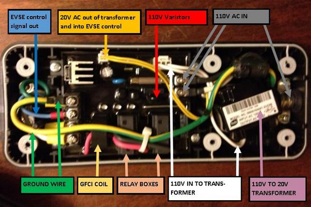
Here's an example from the Level 1 charging EVSE unit that came with our cars showing the before and after chopstick treatment for the control board.

46uuknM.jpg


EFbiw3I.jpg
 
I've used Kenny's chopstick technique (edit: suggested by Kenny) many times on Elcon chargers, which have a thinner coating of what appears to be a similar potting material. I can attest that it works well!

Kenny, have you found a source for a replacement for this potting mix? I usually use a spray-on PCB lacquer, but it doesn't look anything like the same, and there may be advantage in Mitsubishi not noticing glaring changes, in the admittedly unlikely event that they take the cover off any module (rather than replacing the whole thing with a new module). Whatever was used, it would have to be rated for at least 400 V, not have an acid cure, etc. Something like the silicone that you can get in tubes for caulking guns, but runny.

I've had a half-hearted look at our local hardware stores, with no luck so far.

Edit 2: Plus, actual potting mix would look so much better than a clear coating, and it would mechanically protect the larger parts from vibration. at least to a degree. Also, we've been assuming that the potting is of the rubbery / silicone kind. Some are really hard, and have to be melted off. Do we know for sure that it's the rubbery kind?
 
I’ve found someone in my local area who can replace the resistor so I’m removing the inverter at the moment.

Can someone tell me the secret to this connector? Where is the release mechanism?

https://imgur.com/a/P9mZyxe

Thanks
 
Back
Top