kiev
Well-known member
What DTC does it throw now? i hope it is a different code.
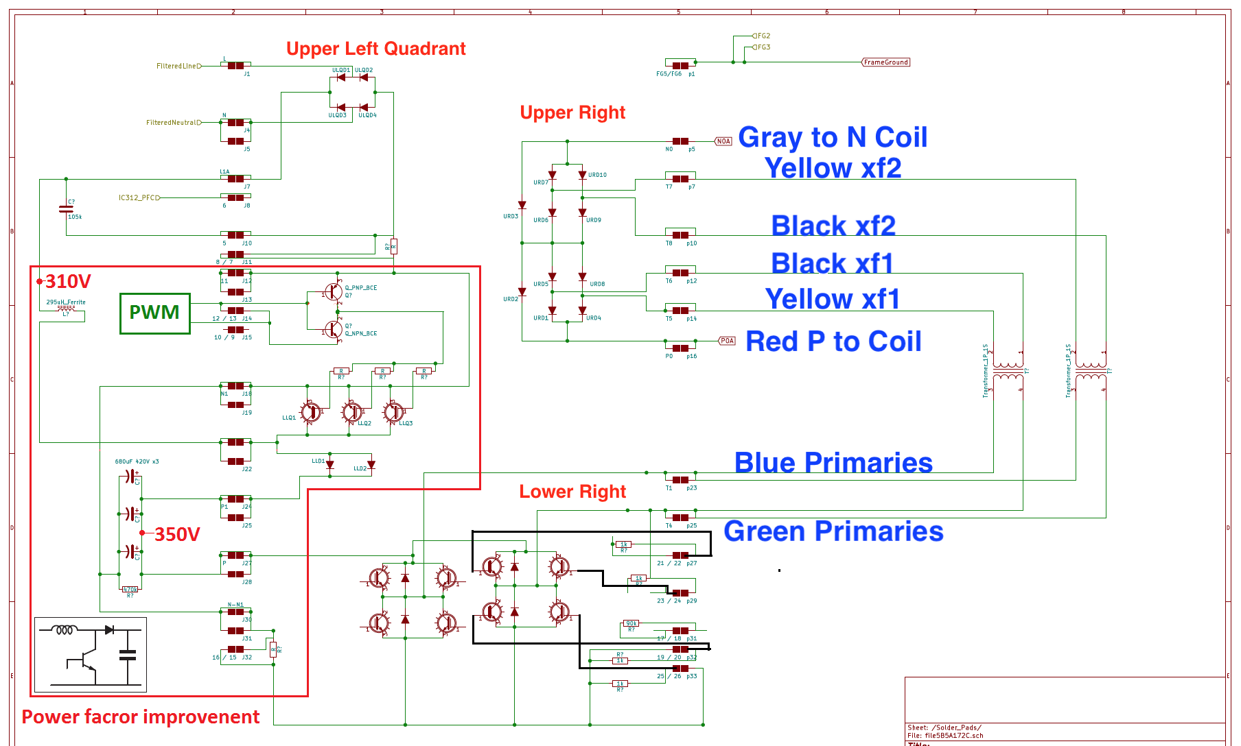
In post #2 on page 1 is a section with a schematic of the waffle plate soldered under the power board. Also is a link to the diode drops that can be measured at those 72 solder joints while still on the board.
Other ideas if the waffle plate measures okay:
Sometimes when the snubber caps explode they splatter molten metal onto the bottom of the control board and short out pins on ics.
Did you check the continuity thru the installed flat ribbon cable from the connector pins on the power board up to the connector pins on the control board.
The 12V battery voltage should come up to 14.4 now when it goes to READY would indicate the DCDC is working okay.
")
