No READY. P1A15 error. Condenser charge timeout.

Mitsubishi i-MiEV Forum

Help Support Mitsubishi i-MiEV Forum:

This site may earn a commission from merchant affiliate links, including eBay, Amazon, and others.
Next tests

Input 4.00v on vl vh with hybrid board still fitted to main board

Input on pins 4 and 5 15.00v

Voltage across vl too:

B and c -0.457

Op amp output -4.01

Lv- -7.65

A and d 1.3mv

Lv+ 7.09v
 
Thanks for that, i should have mentioned to check the Output of the hybrid to compare with the input, but i believe it will be low due to several factors,
The two supplies are not matched + and -;
The A&D is not matched or even close to the B&C (these are the control signals for the 4066 Switches)

i'm going to get some measurements with oscope on my board to see what sort of AC is riding on the LV supplies, etc.
 
50v ac

Just another test I have done

Is to apply 30v dc to pin 1 of cn4 as it’s as much as my supply will do!

Tracing it through the wiggly row of resistors it drops about 5v on each until hv and it is then 315mv on the input

The output on pin 3 is 301mv
 
That was a good test. It is a 4% error on that low level signal. so it is still in that state of somewhat working, but not working as expected.

On my board, with 15.0 Supply using multimeter:
LV+ 7.38
LV- 7.49

A&D .131vac
B&C .061 vac
 
just going over old ground

the resistance on my new board between vh and the pin on the op amp is 6k??? not 100k

my old board is 100k but i replaced this resistor with one you suggested kenny? is this why my old board is now reading less?
 
i'm not following which board was changed, but the spec value is 100k for the input resistor, Ri. You may have made some changes when trying to adjust and increase the gain on the old board, such as putting 1.5M in parallel, etc.

i wouldn't recommend to replace any of the blue resistors unless you are sure they are bad. Those are high precision resistors. Here's the picture
3dJRlQy.png
 
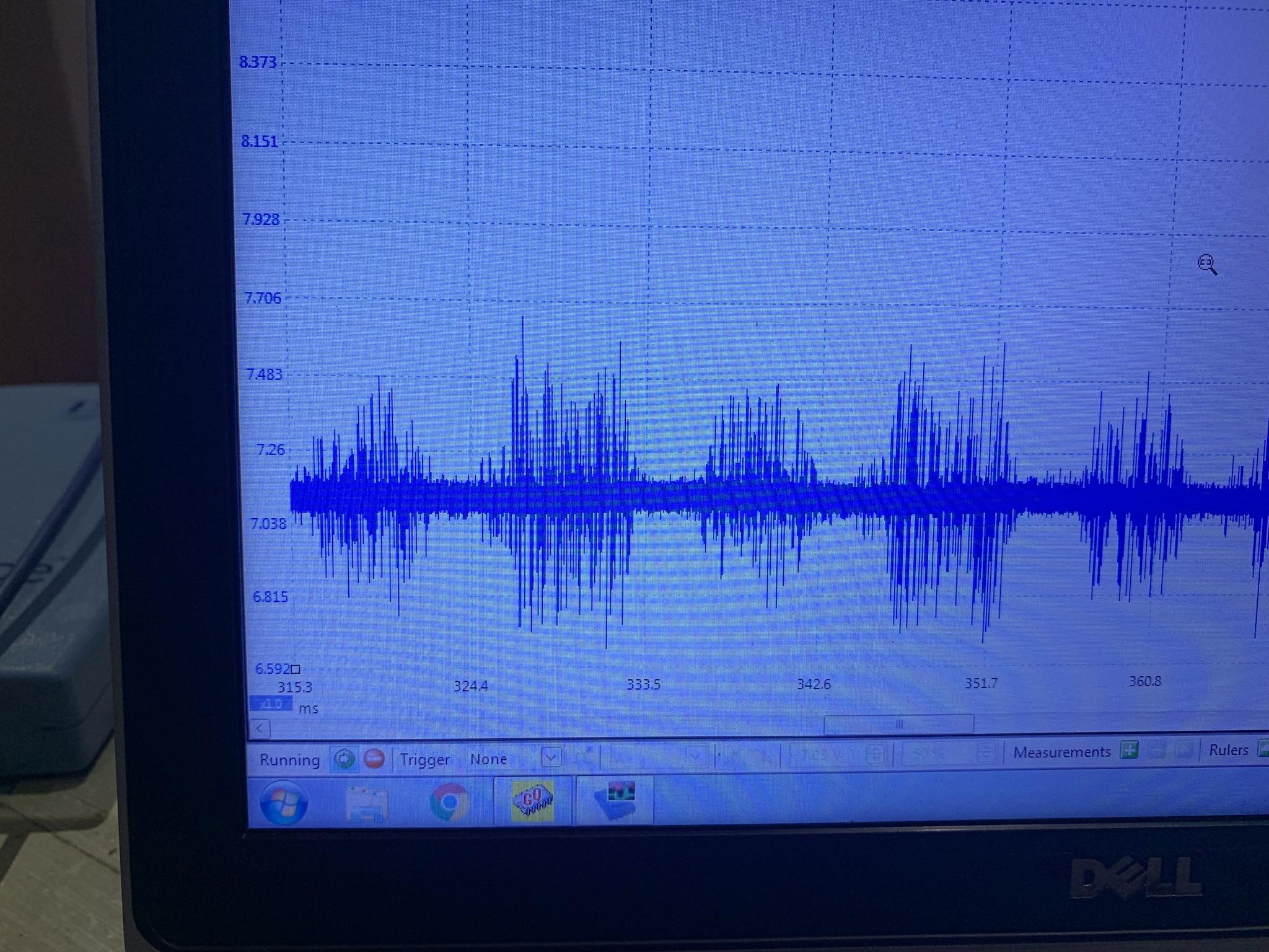
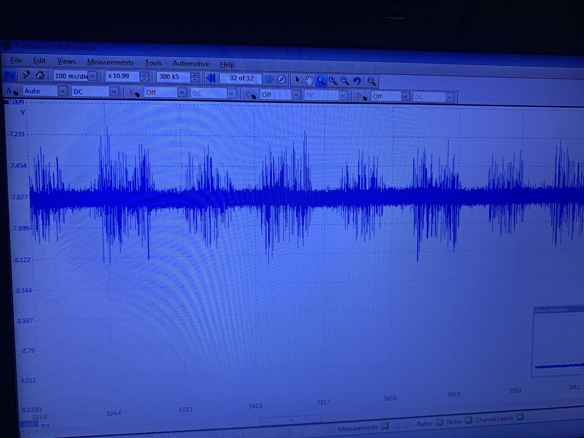
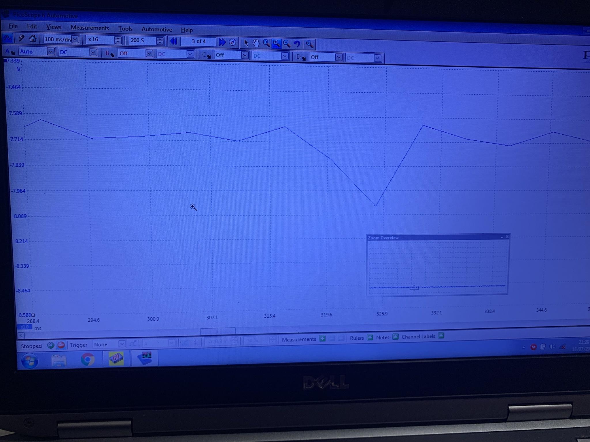
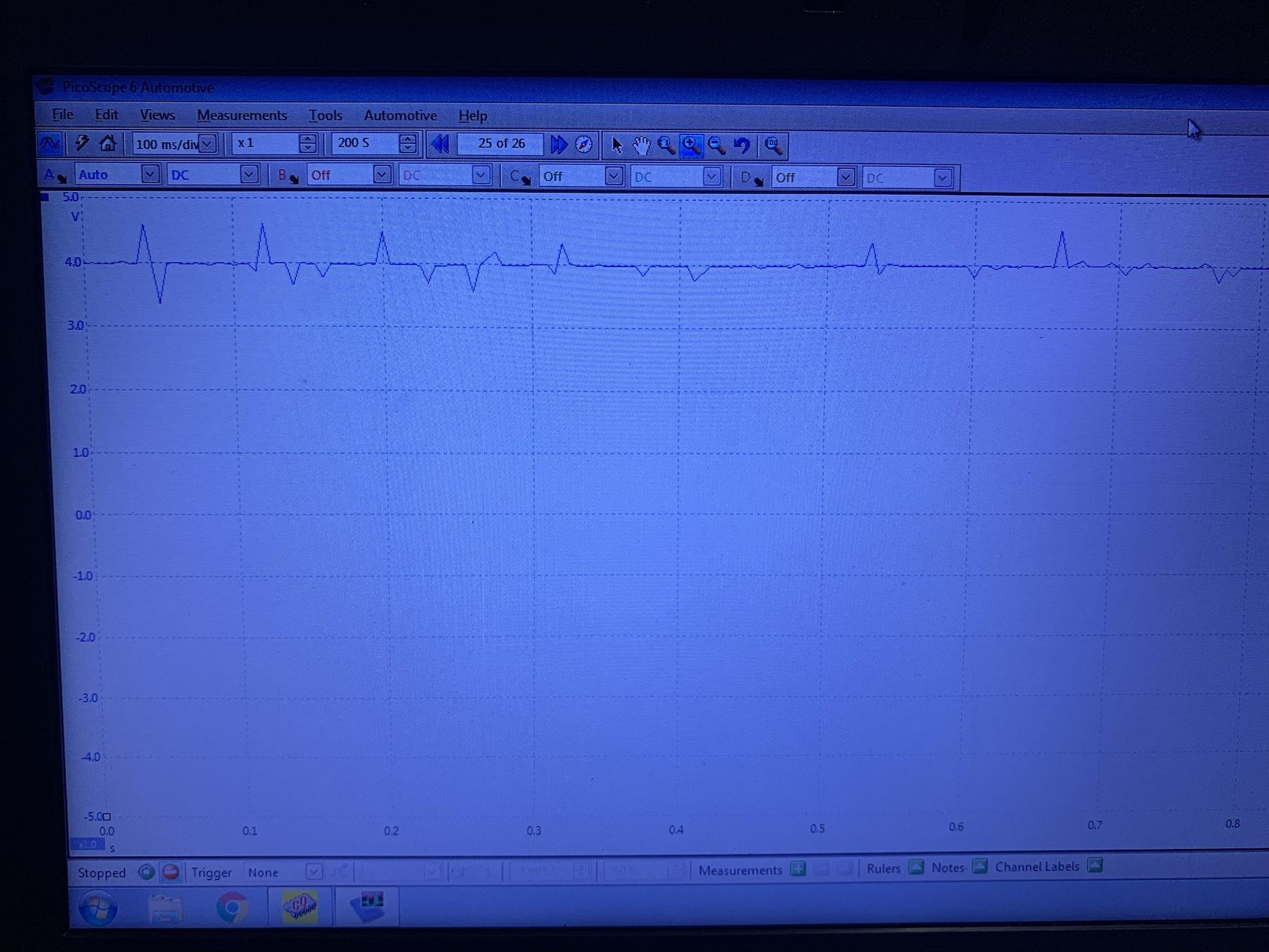
With 15.0VDC for my supply, i measured +7.38 with multimeter for the V+ low voltage supply, and used the scope to look at the ac ripple on top of this, which looks to be about 50mV.
hewgGzu.jpg


i measure -7.49 using a meter for the V- low voltage supply, and also looked at the ripple, about the same 50mV but it has a really sharp edge.
HWZjGF1.jpg


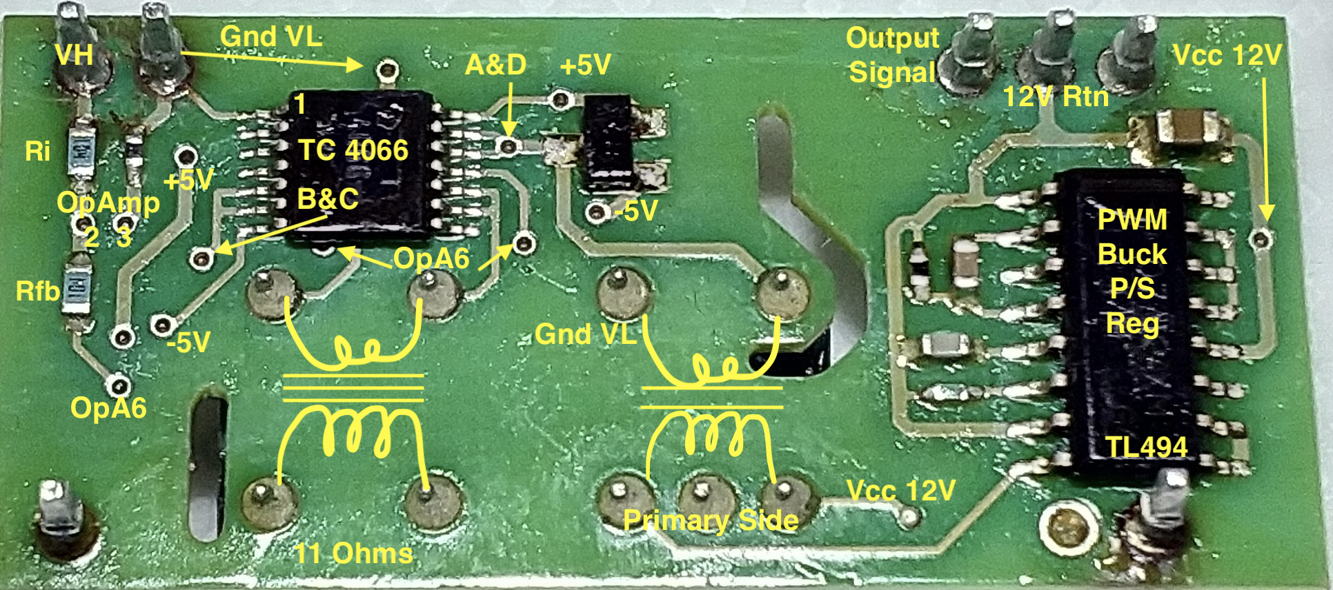
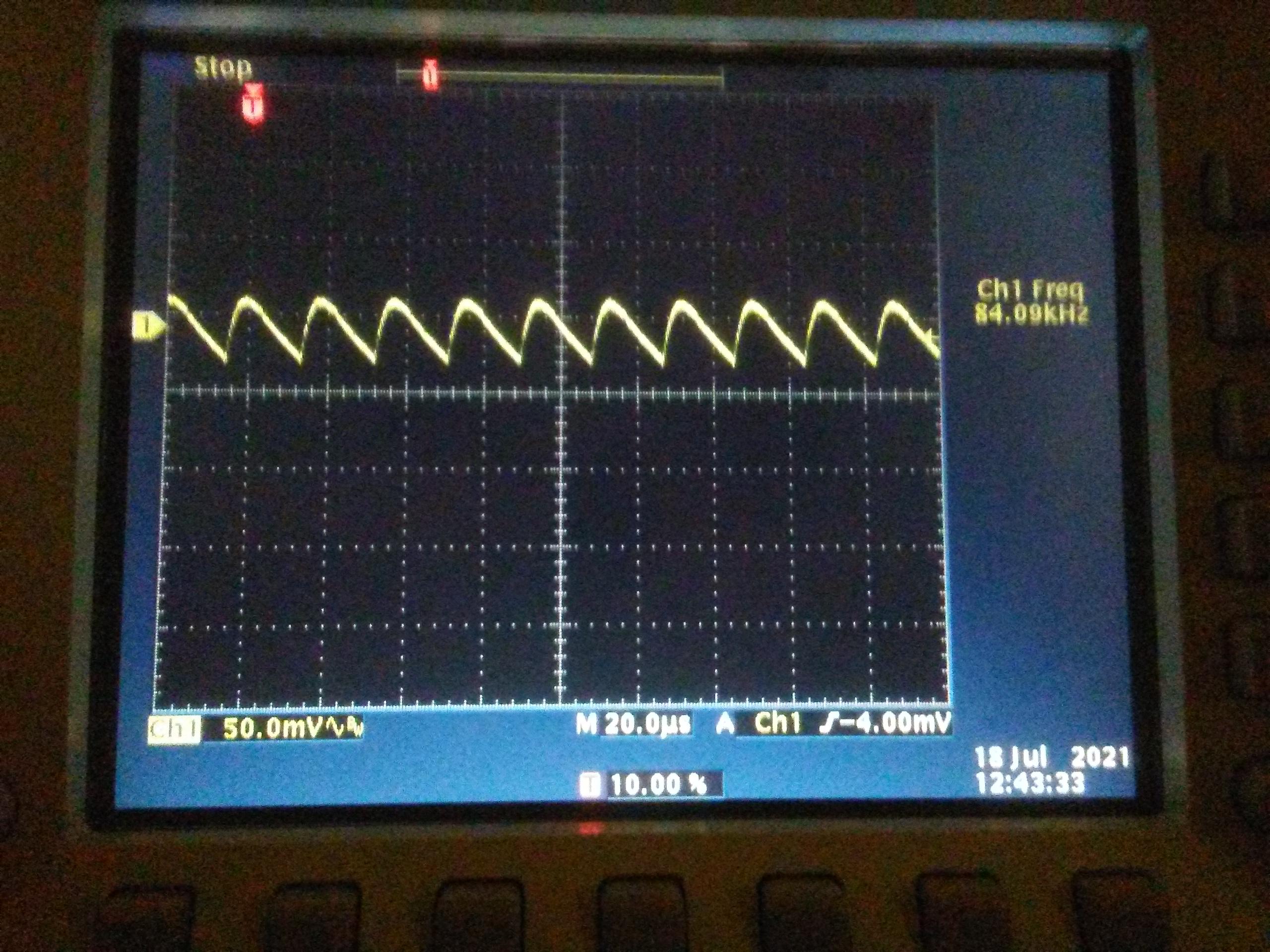
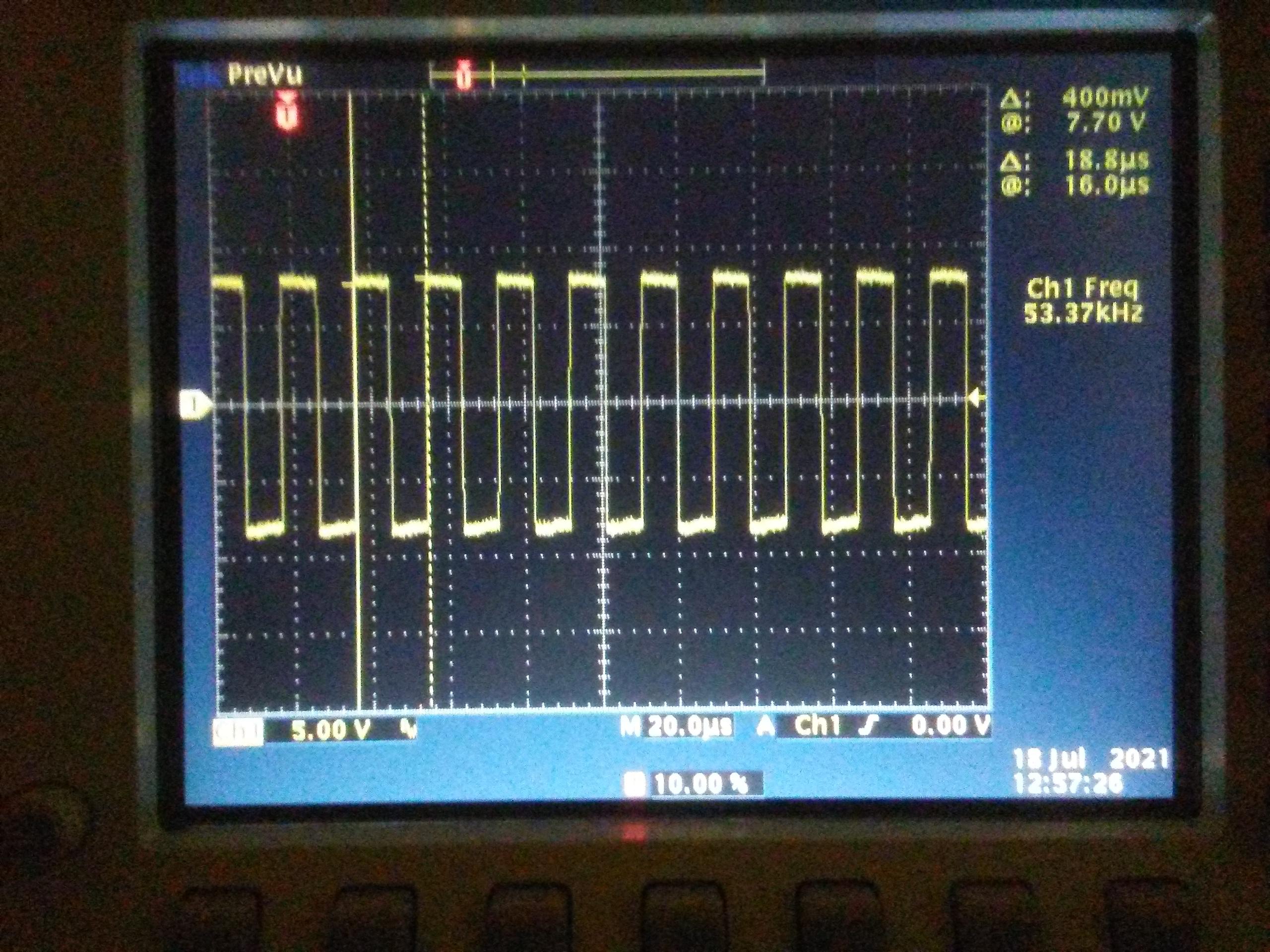
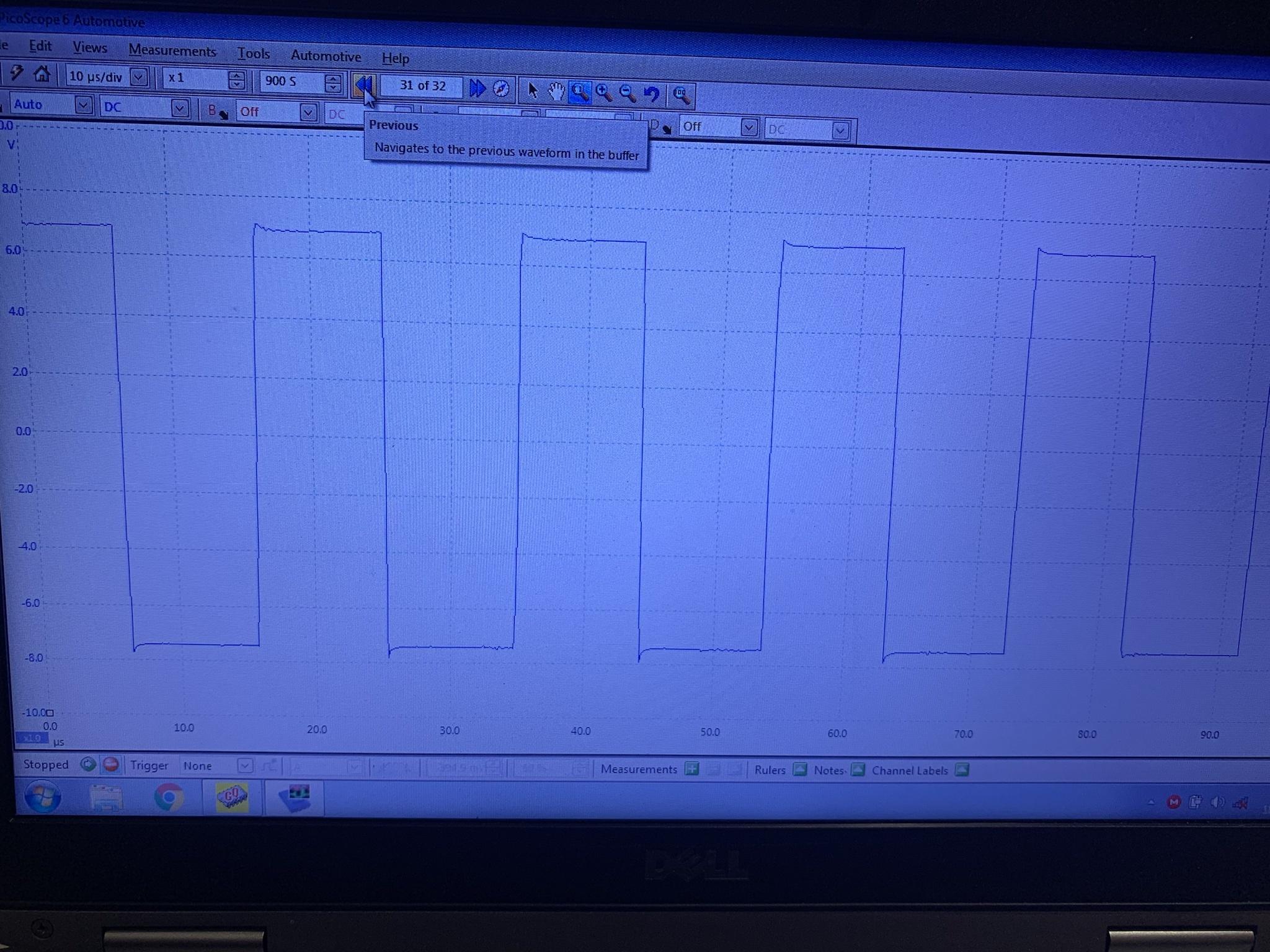
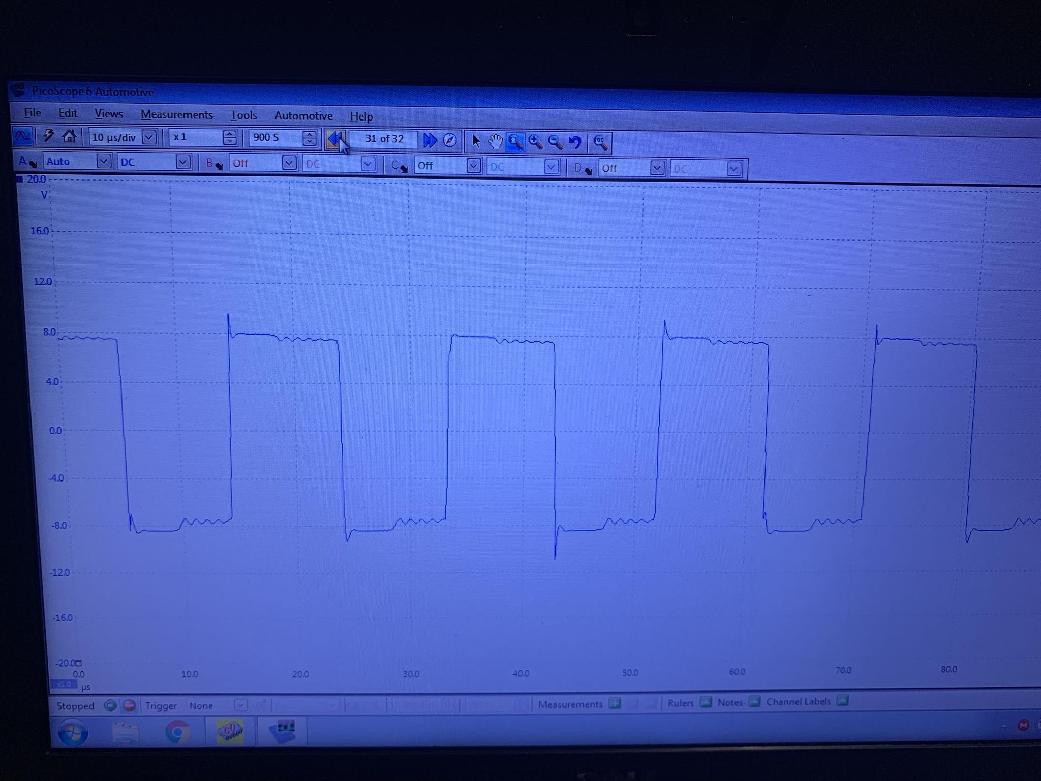
Using the scope i looked at the A&D Switch Control signal, this is also the output on the secondary side of the power transformer.
nozJvk4.jpg


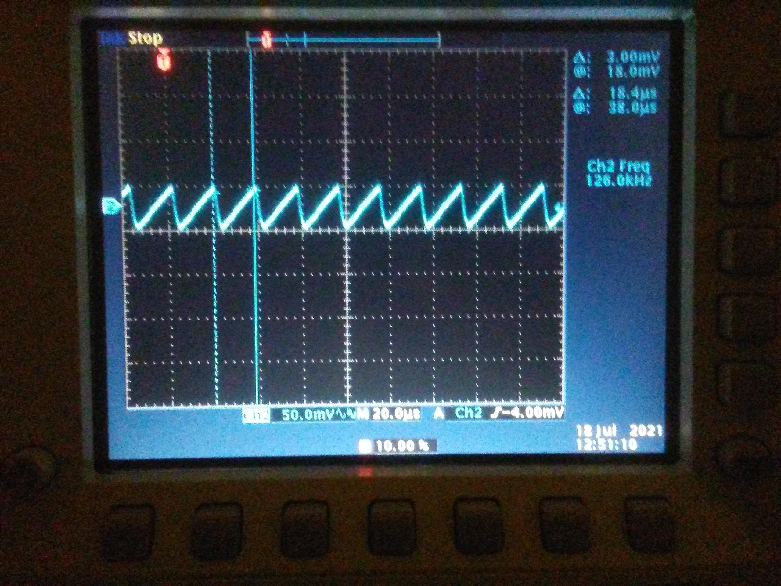
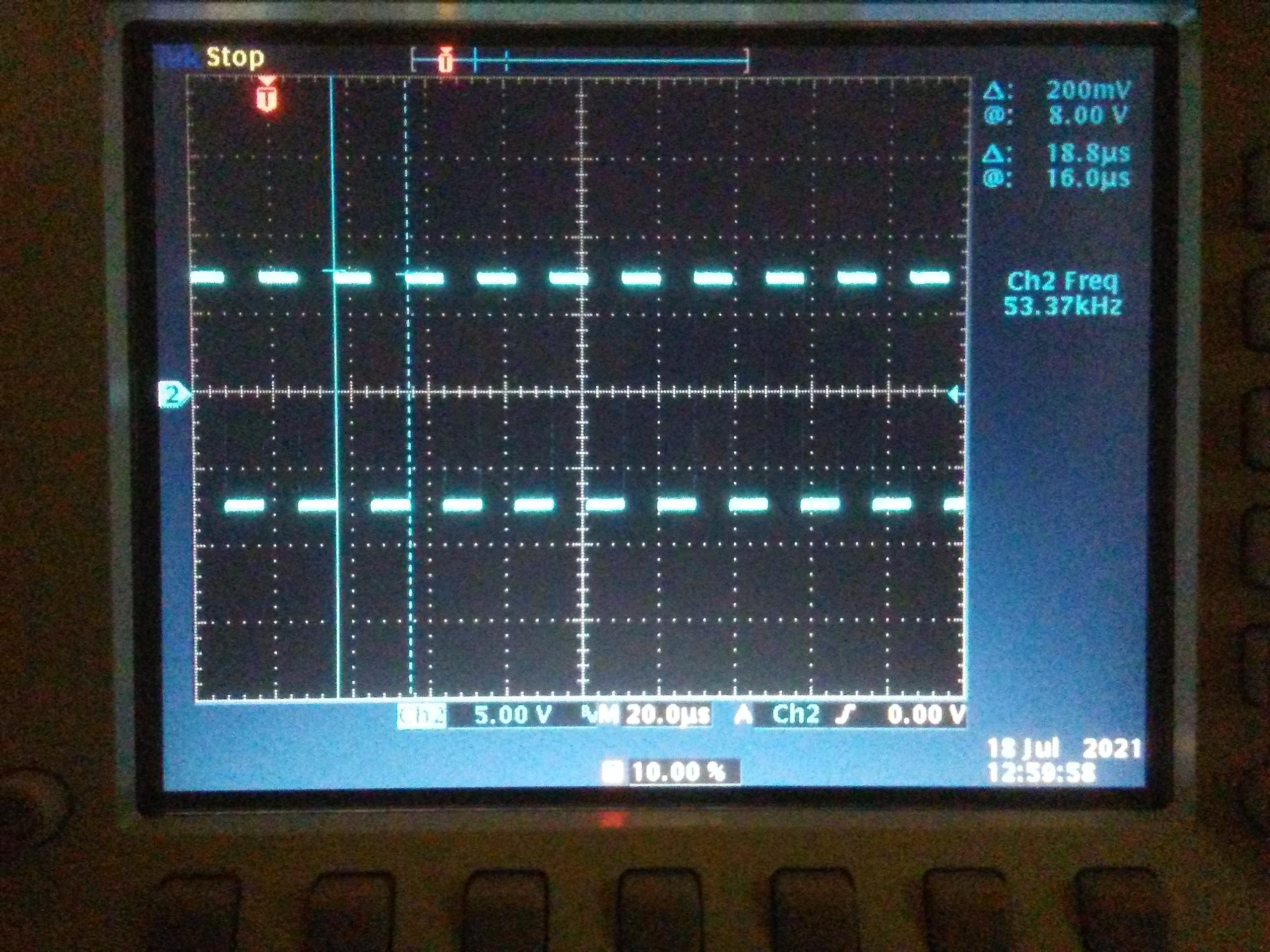
and the B&C side Switch Control signal, which is the output of the single inverter gate chip.
vVzDIHx.jpg


The control signals are switching at the same frequency of the PWM, ~55kHz. The scope frequency measurement on the ripple seems to be at a higher frequency, but just looking at the trace it is the same as the control signals. Not sure why the scope is confused.

i think these are the signals that must be examined to troubleshoot this board, or at least these would be useful to determine whether the board is operating properly or has a fault.
 
Thanks kenny cool pictures

I will have to get the scope now, I dont use it very often so you will have to bear with me!

do you have to pay to post pictures directly to the forum
 
No cost at all to post pictures. Once it is on imgur in your album, you can click on the album picture and there will be a menu on the right hand side with links for sharing with BBC; click on that box to copy to clipboard, then paste that link in your message. It will have the link to the image wrapped with an img tag and /img tag.

4SCWOtz.png
 
B&C looks clean with nice flat tops; A&D has a little something going on at the tops, like a ripple, but they should be adequate to switch the 4066, it is looking for a 5V level to toggle the switch.

The LV supplies are up in the 7 volt region, not sure what all that hash noise is on there or if it could be an issue?

The high frequency noise/ripple/whatever it is, seems to be about +/- 250 mV in periodic bursts.

Not sure what to make of this. Appears different than mine, but does that make it degraded?

i wonder if the hash gets worse with localized heating? Or if the A&D signal collapses with heating, etc.
 
True, but an op amp could easily follow that--it is quite slow

Does the output follow the input? Is the output still degraded voltage?

The low voltage supplies seem really noisy, but i don't know what to recommend at this time.
 
Yes

this is the new board and input voltage is 4.00 and output is 3.75

the voltage supplies are bench supplies and probably not the best. But best I have got!

the 15v supply is rated at 100 amps so a little out of its range on this job!!!!!!!!
 
Back
Top