coulomb said:
Indeed there must be a shunt there.
From an earlier CAN bus log, I noted that the DC output current was being reported as 25.5 A, the highest possible value (0xFF = 255 tenths of an amp). Initially I assumed that this was because of my bench configuration, not getting CAN bus packets from elsewhere. But member Kiev reminded me that in the 2012 and later charrgers, there is an 8 mΩ shunt that ends up reporting the current. I then recalled that I'd seen Iout+ and Iout- labels on the output module PCB. So that's the biggest clue so far about what's wrong with this charrger.
Unfortunately, these modules aren't really designed for board level repair, but they're not impossible to service, thanks to pioneers that have shown the way earlier. Thanks, guys! I started removing some of the soft potting compound in the output module, in preparation for desoldering the top board from the bottom module. It soon dawned on me that several of these pins were far too close to the plastic wall that holds the potting compound in place before it sets, so I'd have to remove the plastic wall. This wasn't too hard, although the plastic isn't as strong as I'd like:
I've tried to superglue it, and it seems to be holding for now. It should be possible to desolder it now; I just need to visit Weber's laboratory to use his desoldering station.
R444 and R445 at first glance look like reasonable candidates for the shunt resistor, but alas they are 68 kΩ and are in series across the output to bleed the capacitors after the power is off.
To see if there was the expected 8 mΩ of shunt resistance, I made some measurements of the voltage drops from P0 to POUT and N0 to NOUT. I did this by pushing 3.0 A from my bench dual power supply from one of the transformer inputs to one of the outputs, measuring the voltage after the diodes (P0 or N0) to the output (POUT or NOUT). I came up with 45.4 mΩ on the positive side (so that's PCB tracks plus two inductors), and 53.3 mΩ on the negative side. Subtracting these, I get 7.9 mΩ. Considering the crudeness of this measurement, I'm very happy with this result. It certainly looks like this model has the 8 mΩ shunt.
Meantime, I thought I'd make use of these terminals to test the measurement system:
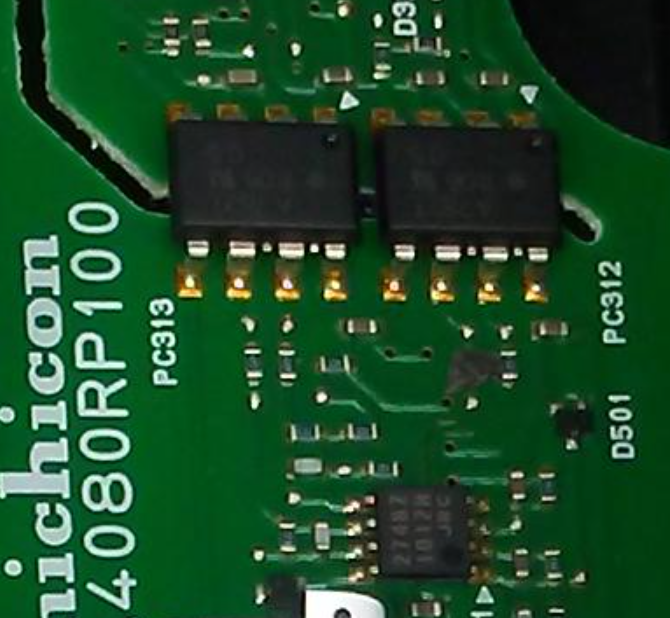
I found it strange that there is absolutely no conductivity between the output terminals and any of Vout+, Vout-, Iout+, or Iout-. So on the lower board, there must be some weird isolating amplifier with differential output. It looks like I can just apply 5 V and some current through the negative side and I should see something happening at Iout+ and Iout-. Here is my setup:
Alas, the outputs measured with respect to MGND:
Vout+: 3.851 V
Vout-: 1.285 V delta: 2.565 V
Iout+: 3.839 V
Iout-: 1.295 V delta: 2.544 V.
Unfortunately, the Iout value did not change at all with applied current. I also tried the positive side, but still no difference.
These seem like very strange voltages to me; perhaps the measurement system is completely broken, or it needs more to make it work. Perhaps 2.500 V represents zero volts and amps, so the measurement can be positive or negative, and only the difference between the outputs is important. It wasn't convenient to put voltage onto the inputs with a third power supply to see if the voltage measurement works at all.
The next step is to find out what's actually down there.


