Hello, everyone
I just registered.
To the point: Defective OBC on I_MIEV Bj. 2011.
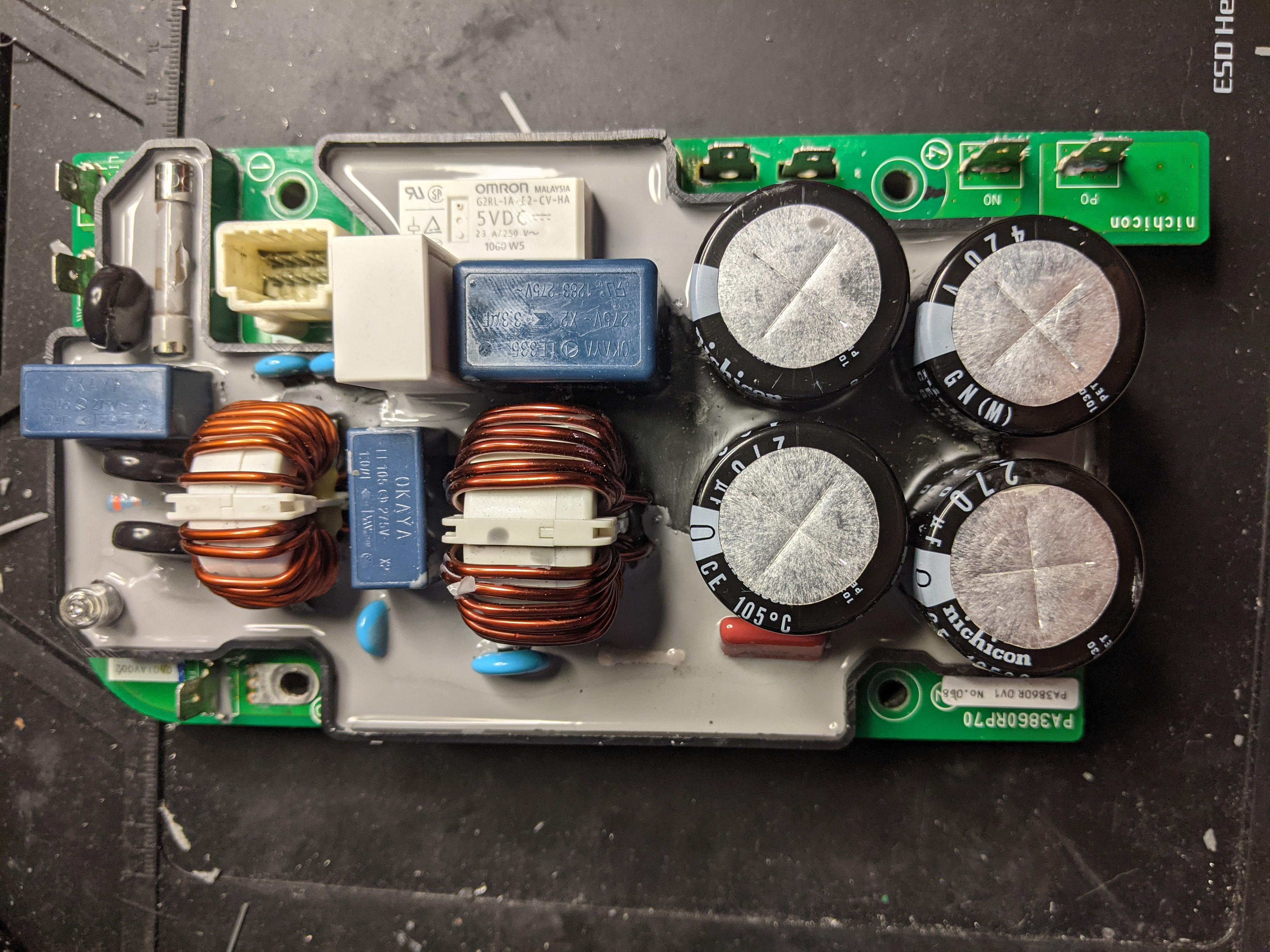
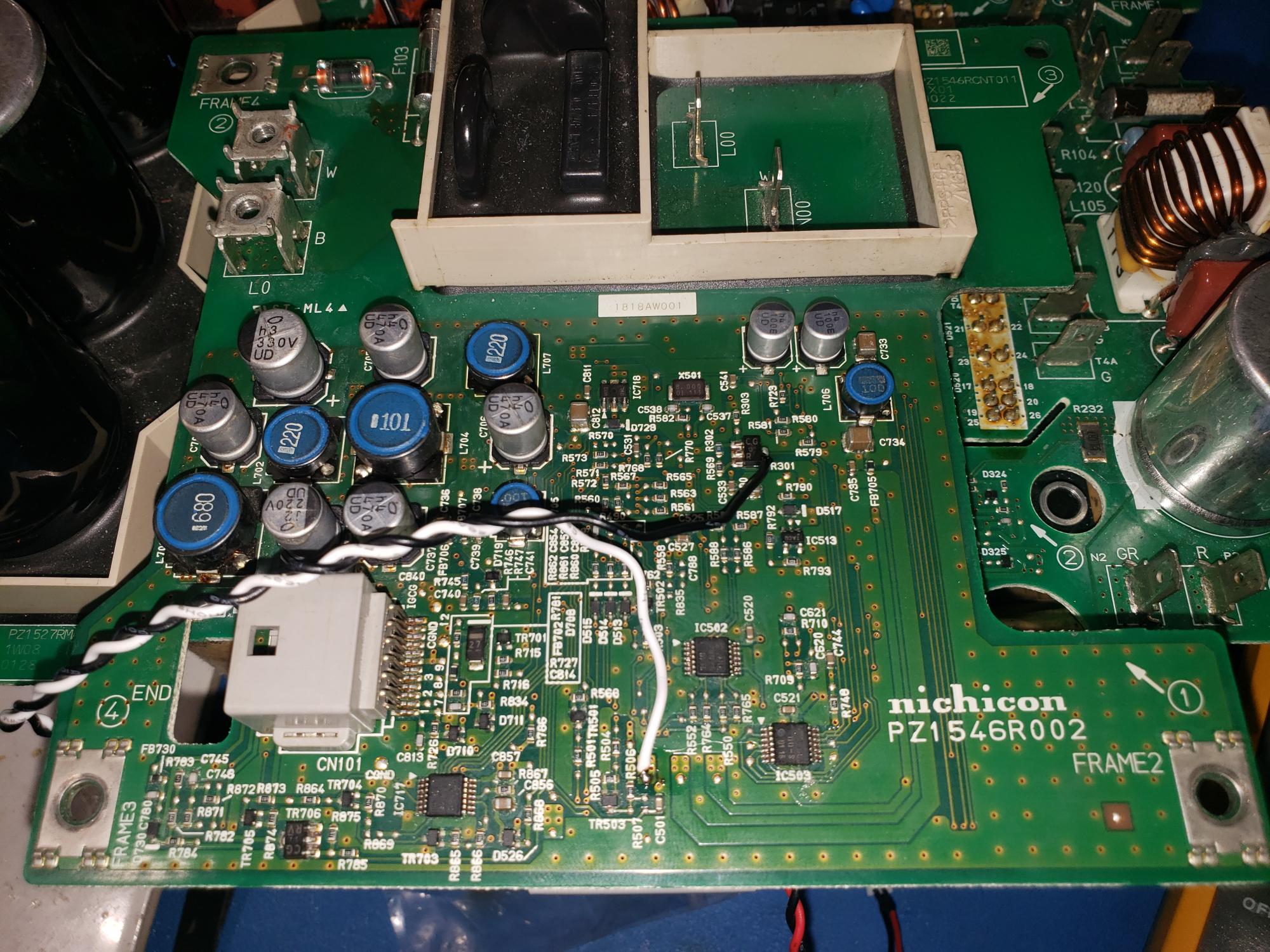
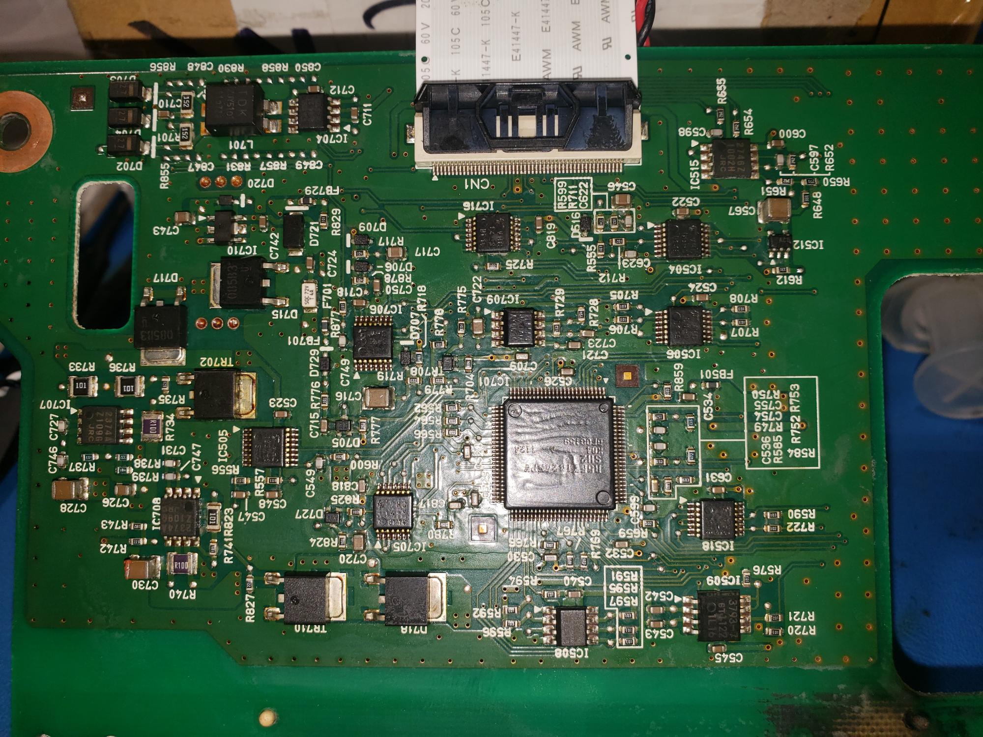
OBC 02/08/2011, with external EMI filter attached on Top of Case.
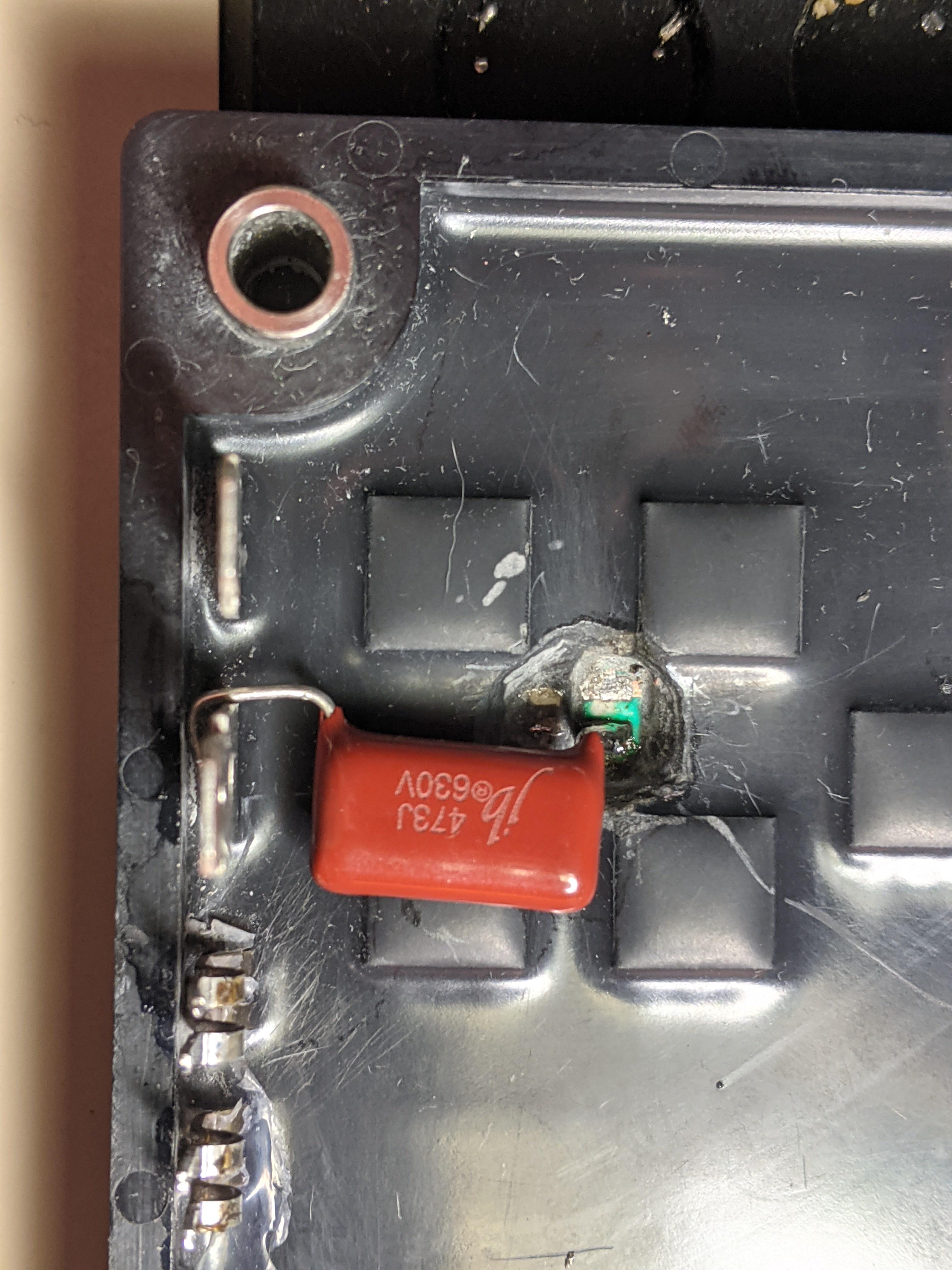
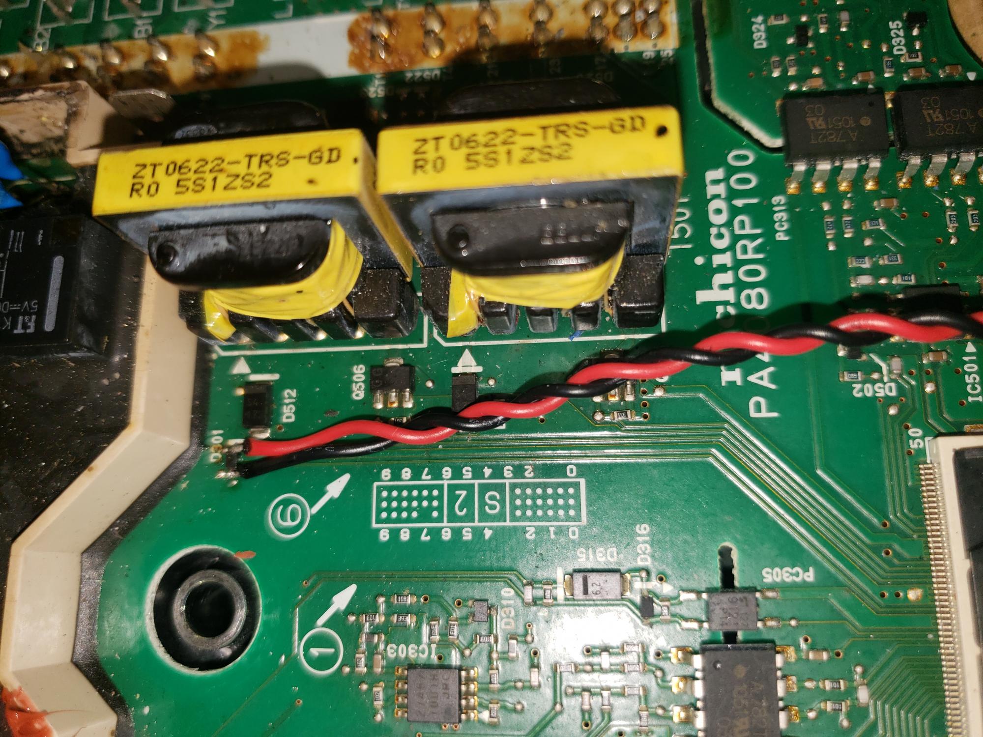
Visible defect on the blue capacitor C122 (one of two) which lies next to the relay center in the cast module on the lower board.
see link:
Mitsubishi i-MiEV On Board Charger (OBC) repair.
MIEV_OBC repair newer year of construction (Bj. 2011.12.25)
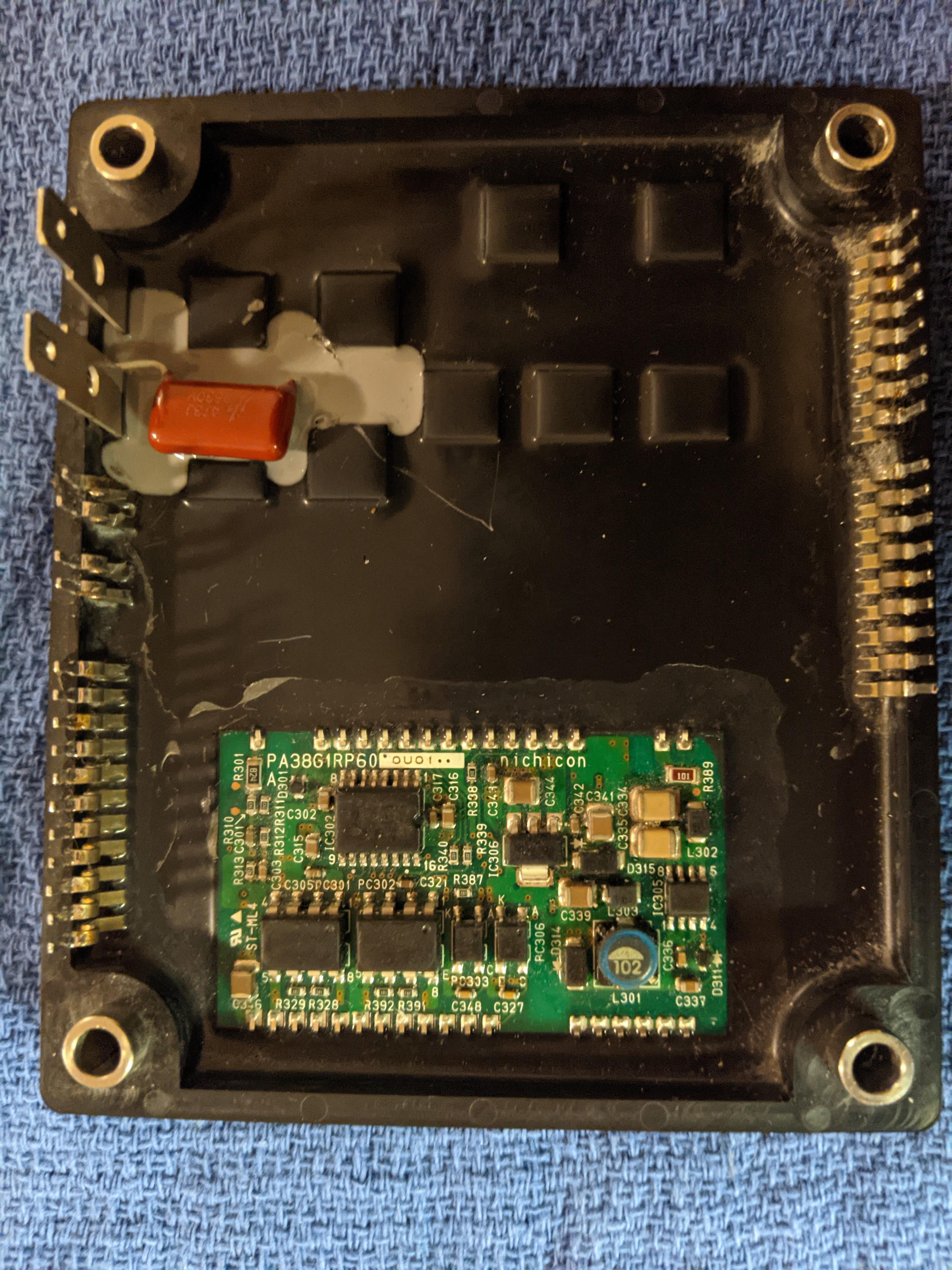
Here the module below with the power semiconductors has been removed to
replace the blue C121 and the green C122 with 2 new blue ones
https://www.youtube.com/watch?v=WVyXuSkn4jc
My circuit board has been removed, the black mush removed in the relevant area.
I checked the defective capacitor and carefully crumbled it to get its PINs free and save them in full length.
Reason: solder the new one to these pins to avoid soldering from below, because in addition,
the module below with the power semiconductors would have to be removed (56 solder points ! )
If I look at the soldering pattern of the 2 free PINs, then I am relatively sure, that the holes are vias (plated through)
So unsolder the pins and solder in the new component from above?
The distance between the capacitor and the circuit board would be 2 mm longer.
(A rough calculation with an inductance of around 1.2 nH per millimeter of cable length can be calculated. (Thanks to wikipedia)
So that shouldn't be a problem?
User Simon seems to have done it because of the soldered image.
Has replaced the 2 blue capacitors with 2 orange ones.
link
http://myimiev.com/forum/viewtopic.php?t=4079
Down the page to the photo series and then to the photo with the heading:
Beautiful Snubber Repair Job by Simon
(on the photo above, with the heading: Bottom Board "DogHouse" - the fenced-in potted area,
you can also see how my "DogHouse" looked like when it was still OK)
Although the second blue capacitor C121 is optically OK, I would also replace it.
2kV, 1000pF 1000pF = 1 nF ceramic capacitor
I documented all the steps with photos, which I will send on at the end of the repair. to:
https://www.goingelectric.de/forum/ and http://myimiev.com/forum/.
After reading a lot in https://www.goingelectric.de/forum/ and http://myimiev.com/forum/.
I examined other vulnerable components for possible defects:
The 2 ceramic resistors component R105 (the larger one) and component R106 (the smaller one)
Component R105 (the larger one) P10K TAM (manufacturer TAMURA) 4.7 Ohm J, 157 ° C.
Looks like new.
Measurement infinite Ohm = interruption!
I stripped the component carefully forensically to see internal defects.
P10K TAM (manufacturer TAMURA) 4.7 Ohm J, 157 ° C 105 (meaning of 105 unknown).
The 157 ° C relates to the trigger temperature of the integrated thermal fuse.
Although this has a declared current carrying capacity of 15A at 250V, it is pure
non-resetting temperature fuse. This is defective.
The wirewound resistor is OK.
Component R106 (the smaller one) 7K TAM (manufacturer TAMURA) 4.7 Ohm J, 105 (meaning of 105 unknown).
Optically OK, only 1 slightly brownish spot.
Measurement infinite Ohm = interruption!
Component carefully forensically stripped to see internal defects.
The wirewound resistor has partly burned out.
Wire diameter both approx. 0.40 mm
So both, probably 5 W.
I measured the 2 ceramic resistors in the installed state, through the narrow gap to the waffle plate module with the power semiconductors.
Used the following kitchen tools from my wife, as measuring tips:
2 x beef roulade skewers made of stainless steel Dm = 1.5 mm L = 100 mm, super-pointed. You can get any PIN.
Component K ??
Relay F + T (manufacturer) type: K1AK005W-KW 5Vdc 16A, 277, VAC RES.
Contact symbol for 1 contact NO, 16A 250VAC.
1040L2 China with VDE mark
Measurement of relay contact, resistance infinite = OK. Relay contact not glued.
Measured at the end of the series connection R105 - R106. Between # 11 and # 14 on user kiev`s circuit diagram.
Measurement relay K ?? Relay coil 5V, 59 Ohm, 85 mA and 0.43 W, energized with source 5V sc 300 mA
(for safety reasons source with small sc)
Energized at the free-wheeling diode D301, positive pole at the diode bar.
This freewheeling diode is missing on user kiev`s circuit diagram.
Relay clicks and contact closes with 0 ohms. Relay OK.
Although the MP capacitor C106, 2.2 µF, 310 VAC, optically is TOP, I also change it to be on the safe side. .
Removal:
The black mush, removed in the relevant area.
I removed the gray wall of the potting module on the small side of the capacitor, (gray wall can be glued on again)
The capacitor, sawn, blown, tattered. Horrific work. :mrgreen:
With an 12V craft drill, with a 2 mm grinding drill, I exposed the pins on the stripped floor.
Undercut the bottom of the capacitor, along its entire length with a fine, long cutter knife to solve it from the circuit board.
Get the 2 PINs in full length L = 14mm.
TIP: It's a lot easier.
Remove the black mush in the relevant area.
Remove the gray wall of the potting module on the small side of the capacitor, (gray wall can be glued on again)
Cover the complete circuit board outside the Doghouse. thigt, to protect it from dirtit.
With an 12V craft drill, with a 2 mm grinding drill, I would only expose the PINs on the small sides.
The PINs, are exactly in the middle of the small sides and directly behind the hard plastic housing.
Then, undercut the bottom of the capacitor, along its entire length with a fine, long cutter knife to solve it from the circuit board.
That's it.
All processes are documented with many meaningful photos.
I would now replace the defective parts, this week. The tension increases.
Important:
Do any of you have any tips on what else I should check?
Thank`s to kiev and others for the great job, you do.
Congratulations! to philsuth, you really deserved the success.
I only read part of the thread, so I only know part of the great people here.
With sunny greetings from Germany
siggs
(The nickname, that the gringos gave to me, instead of the unpronounceable Krautname Siegfried) :lol:
PS:
Thanks to the admin for the happy end, of this Registration. What is the problem ?
So far, I never had a problem with our E-mail.


