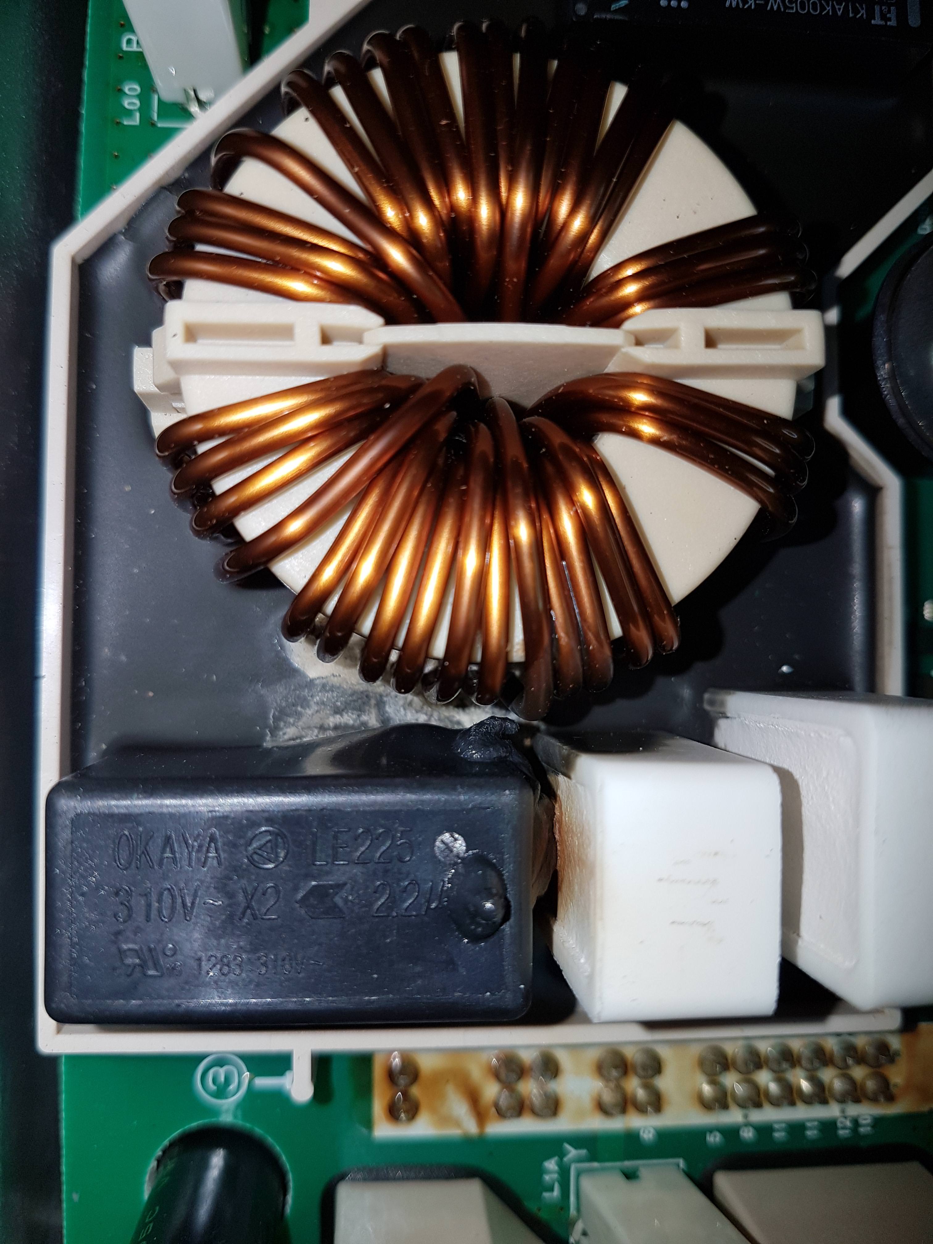
ChristopheFR said:
..
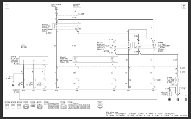
I just tested the 12VDC on the 12th pin
With the charrger cable not connected, I get 0VDC
With the charrger cable connected, I get 12VDC for 2 or 3 seconds, and it stops
Thanks for the pictures, that helps to remember the history.
Charrging is controlled by the EV-EVU.
Your test indicates that the EVSE cable is recognized by the EV-ECU, and it is trying to start the charging session by turning on the relay to supply power to the OBC, but it is not receiving a feedback signal that it requires and turns the relay off. It could be a missing signal from the EVSE or from the OBC.
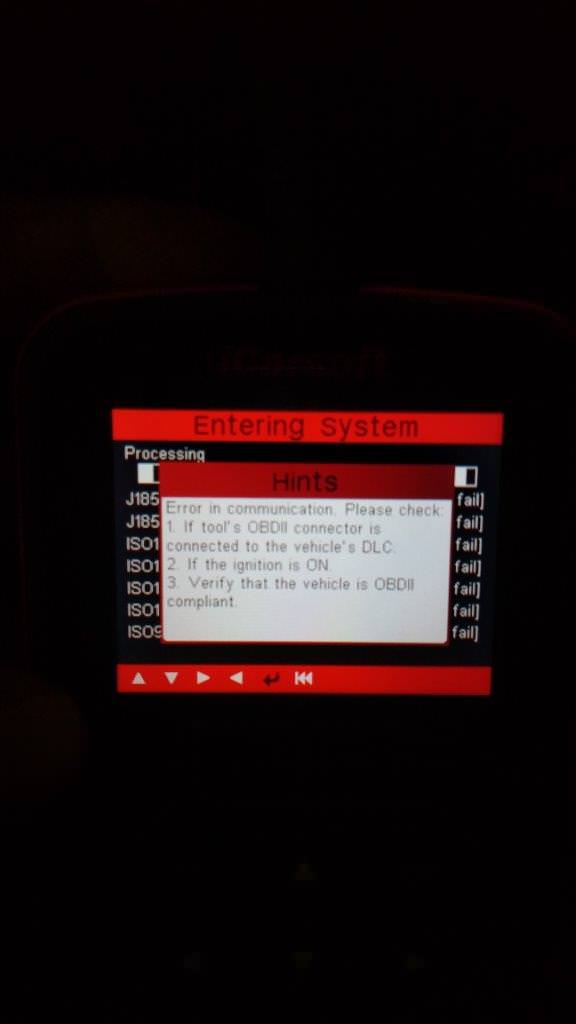
Since your i909 is not detecting 4 of the CAN Buss devices it would seem to point to either a CAN wiring issue or a blown CAN transceiver chip inside the EV-ECU for that CAN channel of the OBC.
i think there is a data item that you could use the i909 to monitor the signal from the EVSE for inserted regular charging and start of regular charging, would have to scroll thru the menu list to find it under the EV-ECU.
Also on the external connector, E-03, pin 7 should have 12V all the time; pin 2 when the relay comes on; and pin 12 is the CHGP line--not sure if it goes high or low to start charging. Maybe you can repeat your test several time to measure the voltage at these pins, e.g. OFF, READY, and EVSE cable plug-in. Might give some clue.
Also would want to ring out the cable between the EV-ECU and the OBC--check for continuity of the CANH and CANL between those boxes, also check that ground pins have continuity to chassis ground.
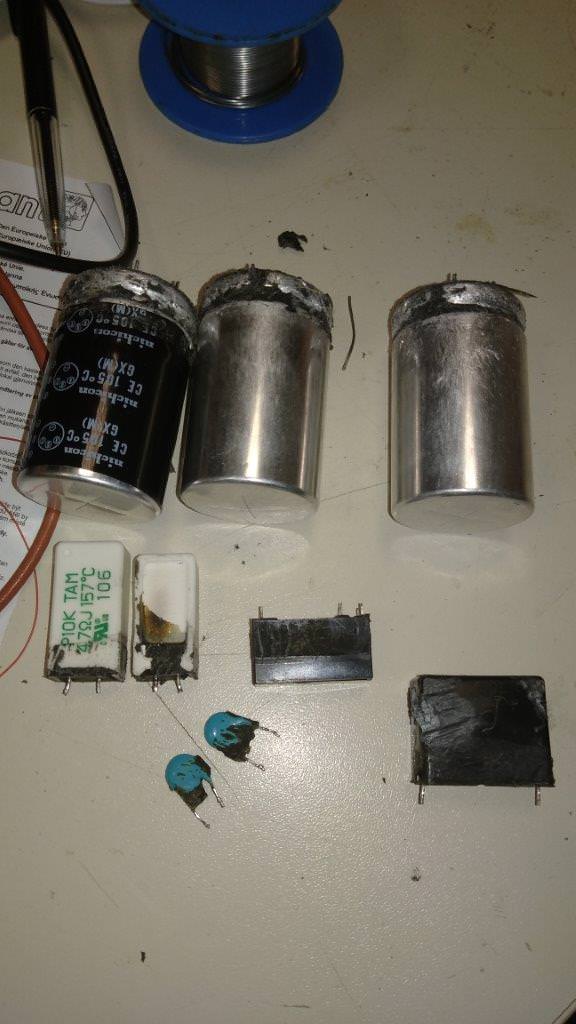
p.s. Just for future reference, it is not necessary to have the exact value for the 3 big capacitors, it would be more important to have the same physical dimensions and pins so that they fit inside the box without the need to modify or hammer out the lid for clearance.


