[ The P1A15 Troubleshooting Thread ] No READY. P1A15 error. Condenser charge timeout.

Mitsubishi i-MiEV Forum

Help Support Mitsubishi i-MiEV Forum:

This site may earn a commission from merchant affiliate links, including eBay, Amazon, and others.
Tenth digit of VIN represents date:
C = 2012

vin-year-chart.png
 
Sorry I've not been around much, life has been a bit complicated lately. Since I've done this repair my car has done nearly 2,500 miles. So far so good. :D

I've got a new batch of the AD202KN pcbs. They are £5 each including UK postage, £6 to the EU and £7 to anywhere else. If you require one message me with your address and email address and I will send you a PayPal invoice.

C8KwuaE.jpg


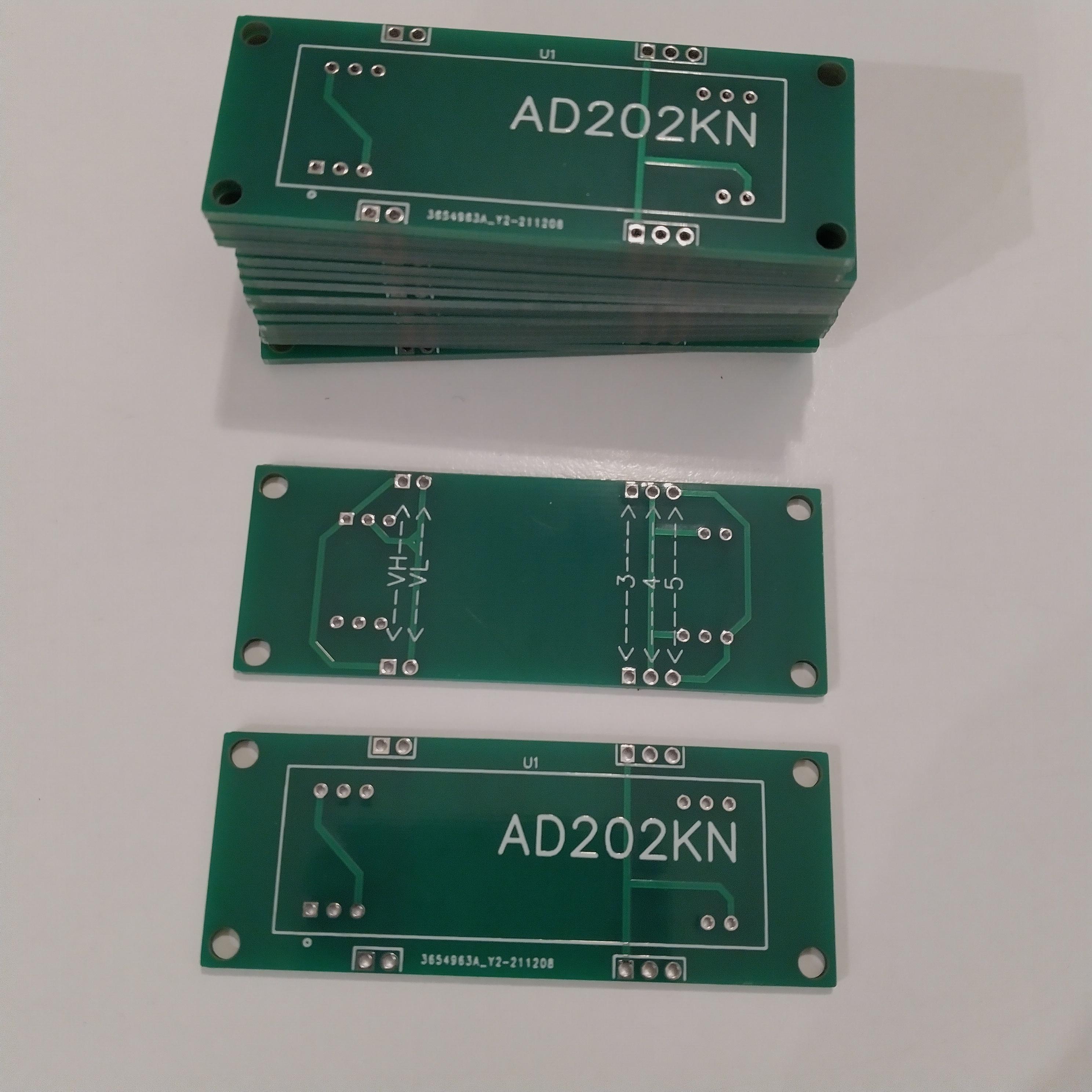
You will need to source the AD202KN, I got mine from Mouser but at the moment they are showing no stock until mid March. Octopart may help you find one. Avoid purchasing these from Chinese/Ebay suppliers as those don't seem to work properly.
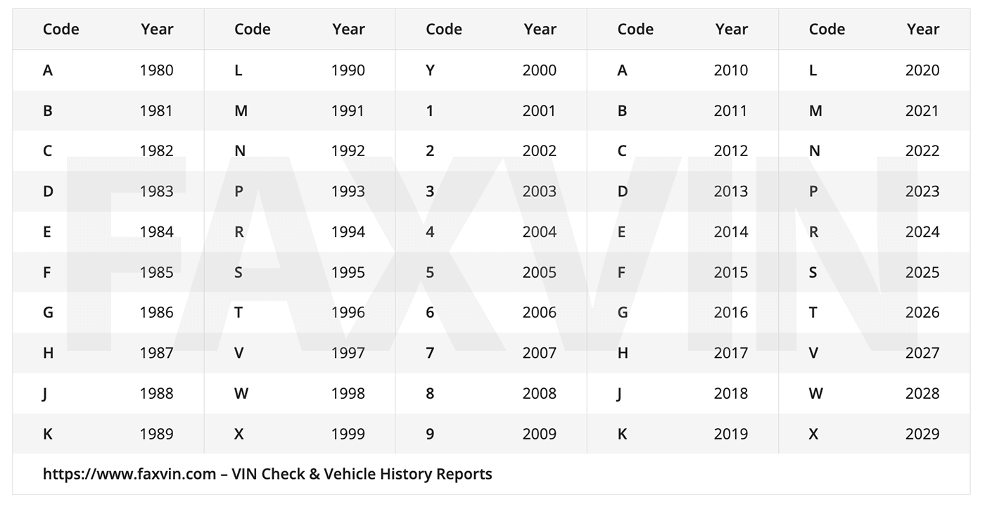
Hi
@GregFordyce
@iso14000
@kiev
Would this replacement part do the job?

AD202KNATI

@GregFordyce do you still have pcb’s for sale, and would they fit AD202KNATI?
 
Here's a tip from @BlindMoose about accessing the bottom control board in the MCU,
I have already done the P!A15 resistor bodge in the MCU. Interestingly, I managed that without removing from the vehicle. Just needed to unbolt from the frame, and lift & twist the box, to get access to the bottom plate.
 
Good catch to find this Dexter.

Thank goodness someone like ATI has stepped up to produce the discontinued isolation amplifier.

Comparing the datasheets, the replacement device from ATI looks identical to the AD version.

It is available in the SIP for $39 vs unavailable at $130 for the obsolete part.
 
hi, i-miev 2009 JDM dtc p1a15. When I connect voltage from an external power source to the inverter input, I see on the scanner screen that the isolated amplifier is working as it should. What's the problem? Perhaps the capacitor has lost its capacity and it is charging too quickly and the machine sees this?
 
Perhaps the capacitor has lost its capacity and it is charging too quickly and the machine sees this?
Typically the car thinks it is charging too slowly--which is the reason that it throws the P1A15 DTC code.

The voltage doesn't reach the expected level in the expected time frame.

A defective hybrid board outputs a lower voltage due to some degraded component (capacitor or transformer or ???).

There is an oscilloscope trace and a scan tool trace showing this in some previous posts in this thread. See the Index in post #1.
 
Indeed it is a little different, thanks for posting about this.

i can see very similar locations of components that do the same functions, so the pcb evolved from 2009 to the 2012 version.

With a totally different hybrid board design it is highly likely that most of the work done in this thread may not apply in your car.

If you can post pictures of the hybrid with higher resolution then i might be able to help, the images are blurry when zooming in to read the marking codes on the ICs.

[edit] i see a variable resistor, VR1 on the control board. That's a no-no to me, as the sliding contacts in a VR are a potential noise and failure source. A sliding electrical contact should be avoided.

They should have used a VR to determine the necessary R for the circuit to work, then replaced it with a fixed precision resistor of that value. The VR is useless since there is no access to it to make adjustments.
 
Last edited:
If the HV value reported by the CAN buss for the MCU capacitor does not match within about 6 volts or so, to the traction battery pack voltage, then the code will be thrown.

Another way to "raise" the apparent capacitor voltage might be to change a resistor in the voltage divider ladder circuit located on the bottom of the 2009 control board (so not as convenient to do as in the later models). But i think this could be more accurate than trying to change the gain by puttin a very high resistor in parallel at the op amp input.
 
Well then it might be in the buffer circuit between the Hybrid Output and the microcontroller, or in the ucontroller itself.

There is also a CAN data value for the capacitor voltage, this is compared to the HV traction battery pack voltage to determine the precharge condition.

How do you know that the hybrid measures perfectly?

Here are some notes i made about the buffer circuit that applies to the 2012, but you may find a similar on your board:
There are test points along the side of the board in a single line of large diameter vias or solder pads. Starting from the corner of the board they are unlabelled and grouped in 6, 6, 8, and 6 vias. i'm going to call those groups A, B, C and D, and pin 1 of each group is the square pad at the end of each group that is connected to the ground plane.

U29 is an op amp used as a unity-gain buffer for the hybrid board output pin 3, which enters U29 on pin 5 and exits on pin 7, then goes thru 1K R245 to a diode D207 and on to a tiny via to pin 34 of the micro U1. The diode is for over voltage protection of the micro in case the signal voltage is too high. The input and output of U29 should be the same voltage unless there is a defect, so you can compare hybrid pin 3 with the test point voltage at "B6" to check for a problem. i think this is the signal read by the micro and reported in the live data on the CAN buss.
 
Last edited:
Back
Top