[ The P1A15 Troubleshooting Thread ] No READY. P1A15 error. Condenser charge timeout.

Mitsubishi i-MiEV Forum

Help Support Mitsubishi i-MiEV Forum:

This site may earn a commission from merchant affiliate links, including eBay, Amazon, and others.
Here's a schematic of the DIP pins to the main PCB connections. The 3 pin connectors on the right labelled pins 1-3 go to pins 3-5 respectively on the main pcb
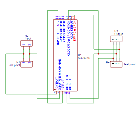
Kivhh20.png
 
Good catch to find the missing solder joint. You have done a great job to make a pcb for connecting it to the MCU control board, and that was a stroke of genius to search and find the AD202. i think there will be many happy folks to hear of your solution to this problem which has been a royal PITA.
 
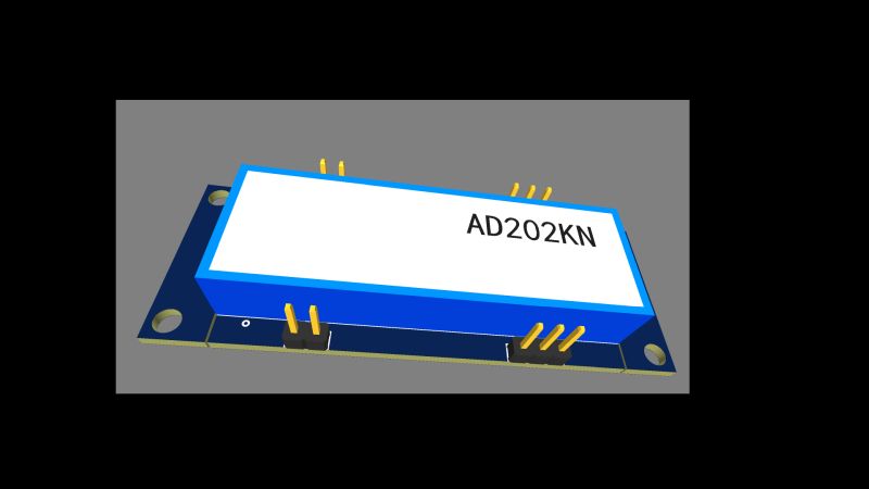
I was able to find the AD202 because of the excellent work already done here to document the existing ISA215N board. :) Understanding how it worked gave me the info to investigate possible alternatives. The AD202 is marked by the manufacturer as 'unsuitable for new designs' so production may be stopped soon. Ideally a PCB for the AD202KY would be designed. The KY variant stands vertical so the PCB could be mounted parallel to the main circuit board like the original hybrid board is. If AD202KN solution works, is reliable, durable and there is demand, I could design and supply circuit boards for the AD202KY.

I should have my iOn on the road by the end of the week. It needs putting back together, prepping for MoT and I'm also going to reseal the Aircon compressor cover so it doesn't get filled with water. Gear selector at back is starting to get stiff and I'll treat it to some new reduction box oil.
 
You guys have done some amazing work there!! Especially on the new circuit board that the new voltage measurement package sits on.

I am one of the people with a car with P1A15 - can I buy a circuit board from you?! Will you offer these for sale to help other cars be fixed?

Cheers!
 
Gary12345 said:
You guys have done some amazing work there!! Especially on the new circuit board that the new voltage measurement package sits on.

I am one of the people with a car with P1A15 - can I buy a circuit board from you?! Will you offer these for sale to help other cars be fixed?

Cheers!

I've got 2 boards left, I've sent you a PM.

I am going to try and design a board for the SIP package which should fit better and then order both boards from China to make available for anyone else who needs one. The SIP package should be a better fit but harder to find than the DIP package
 
I was quite happy with my board bonded to the bottom cover and on flyleads, and as Greg says the Ad202kn is readily available

There is plenty of room and it does make it easy for testing purposes then if it’s removable also then no need to glue it and aggravate the main board.

I have ordered some 100mm leads with plugs and pcb sockets so as soon as it all arrives and I do the next one I’ll take some pictures.
 
I could add some break-off ears to my design that would allow people to use adhesive PCB standoffs for mounting to the bottom cover with fly-leads, or snap them off to mount vertically. What do people think of this idea?
 
So far my car is working great with my PCB. It's now been MOTed and road taxed. I drove it quite hard to clean up the brakes after sitting for over 2½ years and it never missed a beat. No warning lights or fault codes set. The 6 volt difference between condenser voltage and pack voltage seems to make no difference to the normal operation of the car.
 
Nice one. If you could round this work off into a package that is relatively easy for people with moderate skills to install that would be great. I know of other cars at garages with this issue and they seem to be at a loss !

I couldnt see your PM so i've sent you one - I think this forum can be a bit unreliable.

Cheers.
 
What do people think of this design? I've added snap off sections on both ends to allow fixing to the inside of the bottom cover with adhesive pcb standoffs, or snap them off to mount like I did.

VQLtUYg.jpg
 
Looks good Greg.

What does everyone else think about mounting it on the bottom cover? The components don’t run at high temperature and as long as it’s well insulated I can’t see a problem.

Below are the cables I ordered


https://www.ebay.co.uk/itm/JST-XH2-50mm-Connector-Plug-Wire-Cable-Cord-300mm-pcb-mount-socket-/223532031528?mkcid=16&mkevt=1&_trksid=p2349624.m2548.l6249&mkrid=710-127635-2958-0


Just an update, I have now done 60 miles with about 25 stop and starts with no issue, the voltage is still 6v difference even on regenerate.
 
Hi Kenny

It’s always 6v lower at the condenser than the battery.

I looked at the diagram for creating a gain and it’s a little over my head! I could use a decade box to test this on the bench when my next ad202 comes.

I just don’t understand why it wants zeroing nor the resistor with no value on the diagram!

Anyway you are the master so what do you think about mounting the board on the bottom cover?
 
boothegermanshepherd said:
Below are the cables I ordered


https://www.ebay.co.uk/itm/Micro-JST-1-25mm-Connector-Plug-Wire-Cable-Cord-100mm-pcb-mount-socket-/223579971851?mkcid=16&mkevt=1&_trksid=p2349624.m2548.l6249&mkrid=710-127635-2958-0
The pin spacing is 0.1" or 2.54mm. Those are listed at 1.25mm. I suppose you could solder in the wires at both ends.

I've got 90 miles so far on mine, no problems. :)

Does it change polarity in that the condenser voltage is higher than the pack voltage by 6V during regen?
I wouldn't expect it to. Basically, as I understand it, the BMS reports battery voltage and the MCU reports the voltage it's seeing from the battery via the hybrid board. While it's labelled condenser voltage, as the condenser is connected in parallel to the everything on the high voltage bus, condenser voltage = aircon voltage = heater voltage = OBC voltage = MCU voltage. That's why there are so many things that can cause this fault, anyone of those items can pull the high voltage bus low during precharge and set the error. It would appear that as long as the condenser voltage is within an allowed tolerance (12 volts has been suggested) then you shouldn't have any problems. As I understand it condenser voltage is nothing more than a "dead man's switch", as long as it's reporting within tolerance everything will work fine.
 
i was thinking that for Regen to occur, then the voltage at the MCU has to be greater than the pack voltage, otherwise no current will flow back to the cells.

i've ordered a couple of AD202 and will be able to take a better look at the mounting then. i would want to solder any wires at both ends and not rely on a sliding contact of a pin and socket--a sliding electrical contact is to be avoided whenever possible in my experience.

The easiest way to raise the output to match the pack voltage, if that is what you want, then change the 6.8k on the control board to 6920 Ohm 1% or better resistor. This would bias the input higher such the the AD202 output would be read as equal to the pack.

The gain setting adjustment on the AD202 would involve adding a precision 20k resistor between pins 3 and 4 in the SIP diagram of the datasheet, then a 100pF cap and a precision 1.180 Meg Ohm resistor between pins 3 and 2. A 1.2 Meg is a standard value but maybe the other can be found.
 
kiev said:
i was thinking that for Regen to occur, then the voltage at the MCU has to be greater than the pack voltage, otherwise no current will flow back to the cells.
MCU voltage and pack voltage should always stay the same except for a slight voltage drop due to small resistances in the wires, connections, contactors, etc. On regen the MCU will raise the voltage on the HV bus but it will still be the same at the MCU and battery pack.

...i would want to solder any wires at both ends and not rely on a sliding contact of a pin and socket--a sliding electrical contact is to be avoided whenever possible in my experience.
I agree with this but on the other hand the board already has a bunch of connectors already, what's 2 more! :shock: I am coming around to the idea of fixing it to the bottom cover with short fly leads. Soldering is more reliable but soldering to the main pcb with 2 connectors hanging down makes access easier. I'll be curious to see if there's enough room for the conectors nest to the AD202 when @boothegermanshepherd builds his.

The easiest way to raise the output to match the pack voltage, if that is what you want, then change the 6.8k on the control board to 6920 Ohm 1% or better resistor. This would bias the input higher such the the AD202 output would be read as equal to the pack.
I'm against this idea because there is the potential for someone to ruin their main PCB board. I believe my hybrid board got ruined by attempts to 'fix' it. When I got my car it had wires coming off the op-amp on the hybrid board running to a switch and resistors. The previous owner said he had got the car to 'ready' and move in his driveway several times. This tells me that the hybrid board was working at that time, but it was completely dead when I got the car. I think the main issue with mine was the contactors in the battery sometimes making a connection and sometimes not. Point is, I would rather have a 6 volt difference that doesn't cause any issue than have someone ruin the main PCB trying to replace that resistor

The gain setting adjustment on the AD202 would involve adding a precision 20k resistor between pins 3 and 4 in the SIP diagram of the datasheet, then a 100pF cap and a precision 1.180 Meg Ohm resistor between pins 3 and 2. A 1.2 Meg is a standard value but maybe the other can be found.
2x 690k ohm 1% resistors in series = 1.180M ohm. If someone wants to breadboard a working circuit I could add it to the next batch of circuit boards.
 
Hi


"I agree with this but on the other hand the board already has a bunch of connectors already, what's 2 more! :shock: I am coming around to the idea of fixing it to the bottom cover with short fly leads. Soldering is more reliable but soldering to the main pcb with 2 connectors hanging down makes access easier. I'll be curious to see if there's enough room for the conectors nest to the AD202 when @boothegermanshepherd builds his."

I planned to put the connectors on the main board and solder to the new pcb, then have 100mm of fly-leads in some heat shrink just to keep it a little safe from rubbing anything above
 
Before you solder them into the mainboard, can you get a picture of them and the AD202 on my board so I can see if there is clearance?

Another idea for fixing to the bottom cover would be self-adhesive Velcro fixed to the top of the AD202 so the board is mounted upside-down.
 
Back
Top