boothegermanshepherd
Well-known member
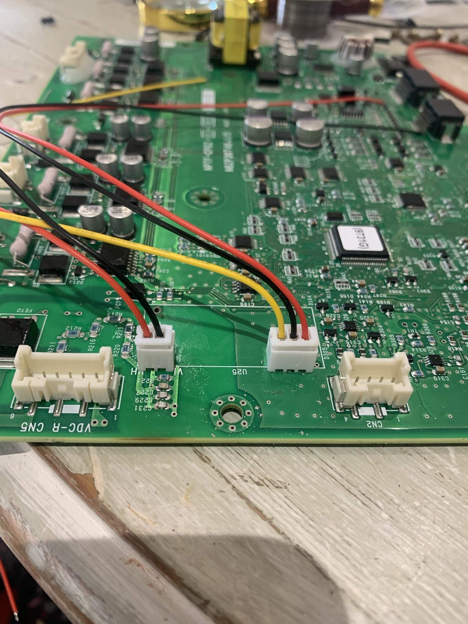
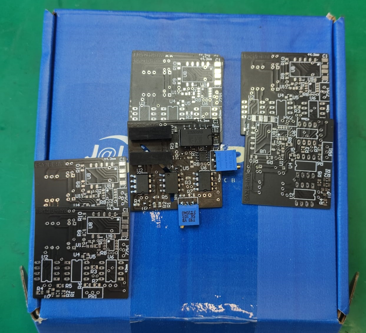
The loom plugs and sockets arrived today and I'm going with them fixed to the main board.


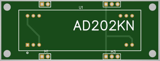
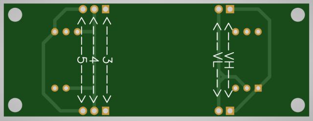
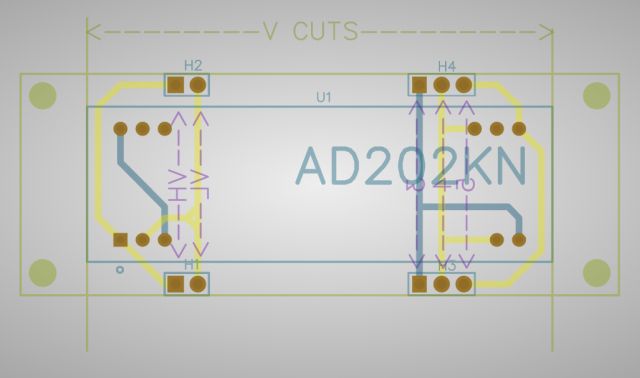
The SIP package would allow a pcb that used all the original mounting points. It is however longer and may need an extra insulation layer between it and the main pcb, or higher standoffs. I was considering doing a design for the SIP, however the parts library I used only had the DIP version, so that would involve creating a part which is doable but I've just had some other things come up that need my time so I won't be doing a SIP version at the moment....i'm curious about what you think for mounting the SIP package?
My wife says I have an unhealthy Velcro obsession!! :lol: :lol: :lol:I’m not a fan of putting anything like double sided or Velcro because I think inevitably with the heat the glue will come away.


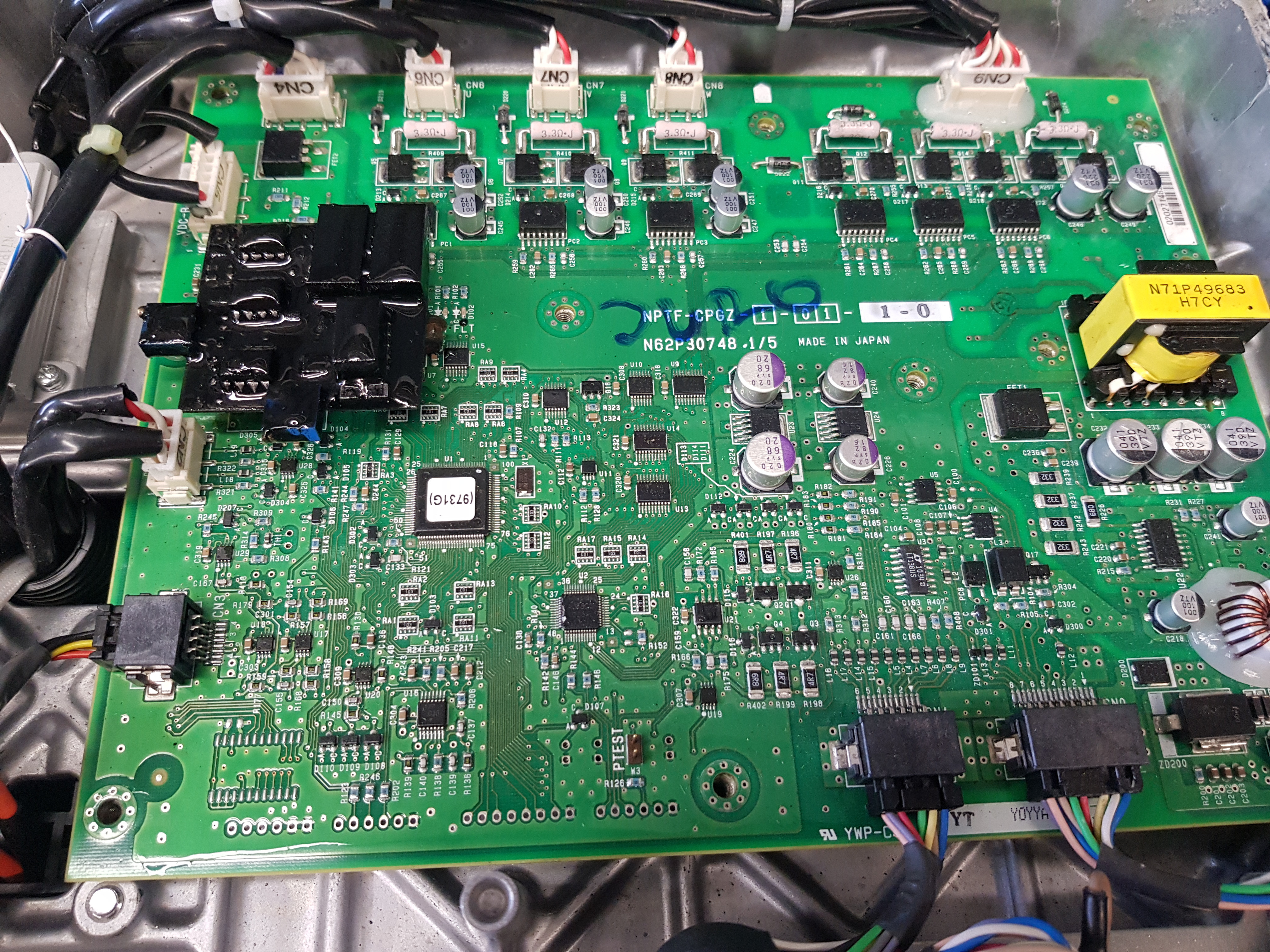
What I don't understand though is what the actual issue is - the voltage measurement is low but as far as I can see the hybrid board doesnt actually measure the voltage, it is just an isolator that passes the voltage along the circuit to be measured later.
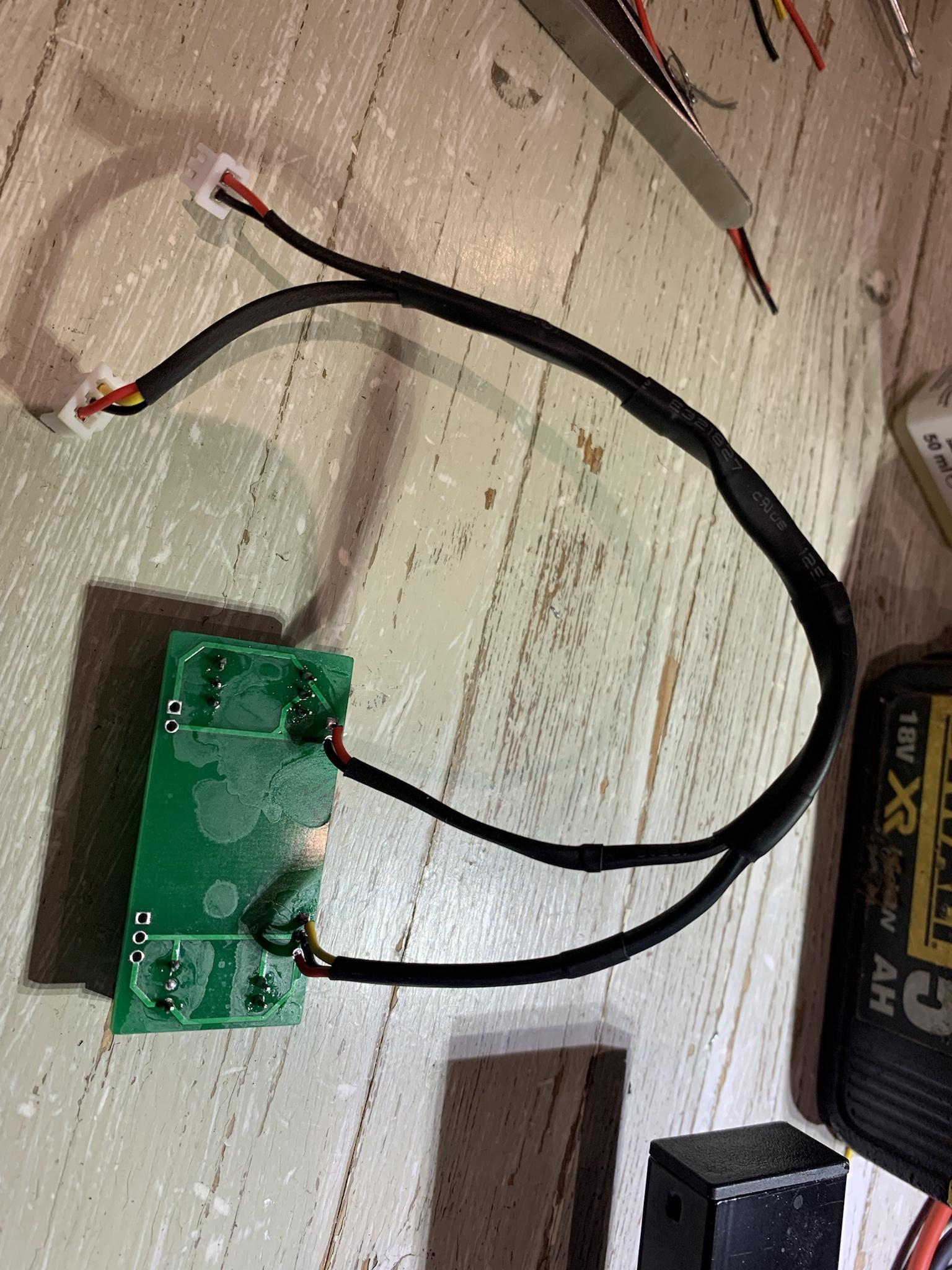
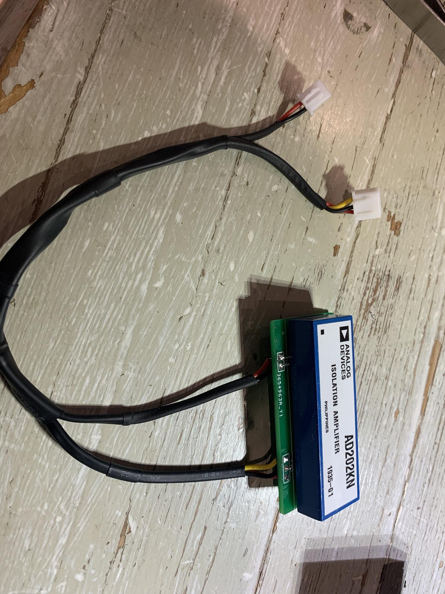
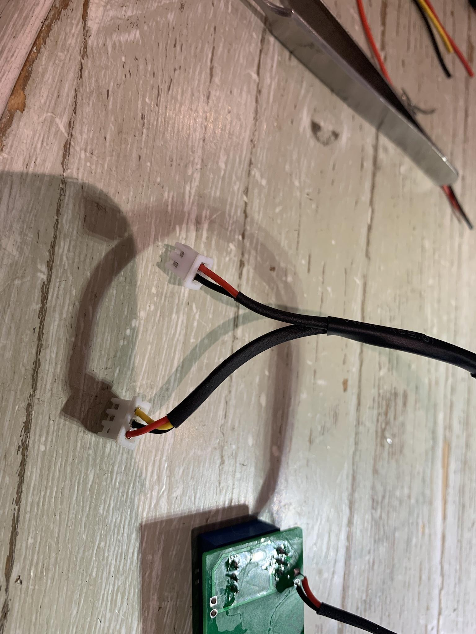
I've bought my czero with a condom on the AC connector (literally) - when I've tried to check the resistance of the compressor so the compressor is damaged and the car arrived from Norway where's its too cold to worry about AC. 140kkm and still 31.9Ah...Where did you tap off the HV?
I'm trying to read the resistance of the HV with a fully discharged capacitor to check for a real short-circuit. Sure thing its a dumb way because tester charges the big capacitor a bit and its a moon phase measurement, not resistanceIf you are reading 800 Ohms
I'm sure what I'm doing - its a hobby toy for me, not something that I'm afraid to screw up. So if it would burn iteslf my only concern would be to make firefighters believe its an accident due to ageing, not my experiments.Not really a good idea to bypass the system to engage pack contactors
no direct measurement performed to both circuits, used a scanner to see the bat voltage. And both multimeter and scanner to see the cap voltage. So BMU is not measuring anyting like that - it summs all the cells voltages instead while inverter actually tries to measure the voltage with the hybrid board.but if you are actually measuring with voltmeter a 12V difference between the pack HV and the MCU capacitor HV
Thank you sir, the more we know of the CAN messages - the more we can fake / patch.CZeroOwner said:Hope this helps
374 (D1 -10)/2 = SoC
374 D7/2 = C
373: (((D3 * 256) + D4) - 32768) * -0.01 = Pack Amps Out (#)
373: ((D5 * 256) + D6) * 0.1 = Pack Volts (#)