You are using an out of date browser. It may not display this or other websites correctly.
You should upgrade or use an alternative browser.
You should upgrade or use an alternative browser.
Not able to drive. P1A15 error.
- Thread starter Gencis
- Start date

Help Support Mitsubishi i-MiEV Forum:
This site may earn a commission from merchant affiliate
links, including eBay, Amazon, and others.
i have almost completed a trace of the ISA board. The final and biggest unknown is the part number/identity of the little 5-pin device on the top near the transformer and op amp.
i'm guessing that it is some kind of dual voltage regulator in an SOT 23-5 package, but the part has been etched on my board and no markings could be read. There is a via off of pin 4 that is an important control input signal to a chip on the bottom side.
Could you please take a look with a magnifying glass to see if you can read a part number? Anyone else with an open MCU control board?
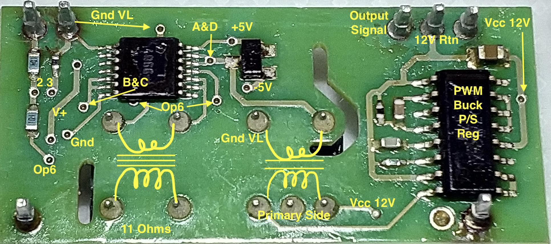
On the top side is the AD8677 op amp, the 5-pin device, 2 transformers (1 signal and 1 for power), a Toshiba 4066 Quad bidirectional switch., and a 3 pin zener diode device. On the bottom side there is another 4066, a 3-pin dual diode, and a TL494 PWM power supply controller chip. So if would be possible to make custom boards if these are suspect and a vendor for the ISA215-HYB cannot be found.
A picture of the ISA board pinouts has been shown in other posts but i will list it here: 1 = VH; 2=VL; 3=Output Signal; 4=Gnd; 5=12V supply.
The P1A15 error code will be generated if that pin 3 signal (0-5V range) is not meeting the necessary ramp-up conditions that the EV-ECU is expecting.
So a fault in any of several parts on this little bitty board will disrupt or degrade the pack HV reading and brick the car. i think we could come up with a way to test this board on the bench with a power supply and oscilloscope. It has no reference designators so we will make up our own.
A quick look seemed to show that this pin 3 signal is sent to the MCU microcontroller; will trace it all the way when i get some free time.
Here is a markup of the bottom side

coulomb
Well-known member
I'm not seeing any controller for the 4066 switch inputs in your list of parts. Could the 5-pin device be a tiny Pic micro or something? Something has to be converting voltage to frequency or PWM, to get the signal through the transformer.
This is of course a wild guess until the schematic trace is revealed.
This is of course a wild guess until the schematic trace is revealed.
My i-miev is still in the workshop.
They exchanged capacitors but it did not solve the problem.
They measured voltage in the battery and in MCU. The difference is 10V. I informed them about the possibility to use additional resistances for correcting voltage readings. With additional resistance, car goes into a ready state.
Now they ordered OPAMP and will change it. We will see the results.
It might be that they could test the hybrid on the bench with a 12V power supply to pin 5 and return on pin 4. Then using an Input signal from 0 to 4 volts on pin 1 (VH) with return on pin 2 (VL), it should be possible to adjust and vary the Input and see the Output on pin 3 vary in the same manner. i would guess it would be around the same level but that depends upon the winding ratio of the transformer. If pin 3 is dead with no output or variation with pin 1, then the board will need additional troubleshooting.
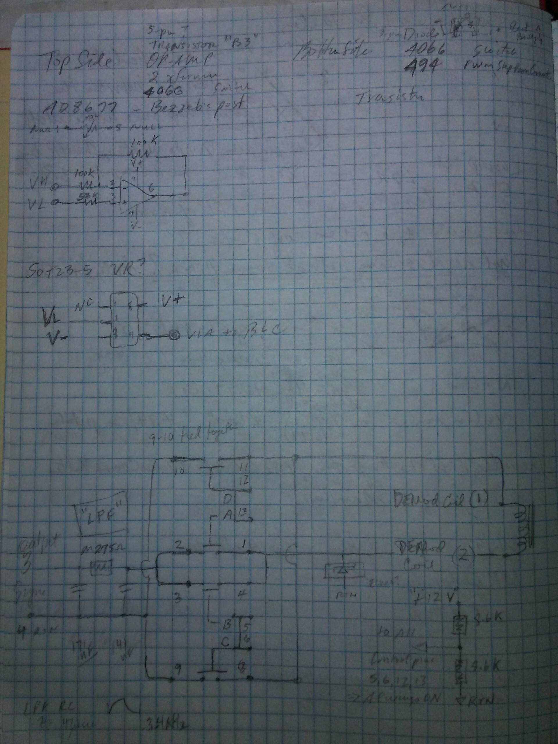
The op amp is being used an a Unity Gain Inverting Buffer, so whatever voltage is Input on VH, should be seen as the same value with opposite polarity on pin 6 of the op amp. If this doesn't occur then the op amp is suspect.
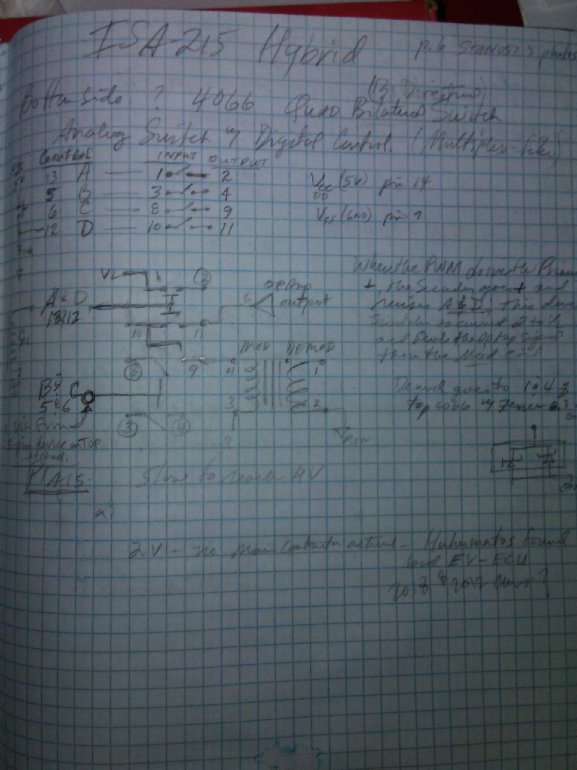
The 12V to hybrid board Pin 5 with respect to Pin 4 is chopped and switched by the PWM regulator chip thru the Primary side of the power transformer. The Secondary of the transformer then creates a +5 and -5V supply for the op amp, and the input 4066, and provides a pulse to the "A" and "D" control pins to switch the gates of the input 4066.
There is a 5 pin and 3 pin device that is involved with the +/- 5V also but that is where is don't have the part numbers.
When the gates of the input 4066 are switched, then the op amp output signal sent thru the primary of the signal isolation transformer; the secondary then carries the isolated signal voltage to the 4066 on the Output side. The output 4066 is constantly gated by a bias voltage created by a voltage divider on the 12V power and the two tiny resistors above and to the left of the output 4066, so the signal runs right thru into a Low Pass Filter seen right at the Output pin 3 of the hybrid. there also appears to be a zener diode to limit over voltage of the Output.
will post a sketch of the trace
Good Luck i hope you can find the issue with their help.

$399.00 ($7.98 / Foot)
$479.00 ($9.58 / Foot)
PRIMECOM Level 2 Electric Vehicle (EV) Charger (220V / 240Volt, 16Amp) Portable EVSE Smart Electric Car Charger, 30', 40', and 50 Feet Lengths (NEMA 14-30P, 50 Feet)
PRIMECOM . TECH

$26.99
KISHACZ 4 PCS Car Door Lock Cover for Mitsubishi i-MiEV 2009-2020, Car Door Latch Lock Protective Cover, Door Latch Lock Cover, Door Latch Guard Car Decorative Accessories,B Black
Yuanpingshilixiuhanshangmaoyouxiangongsi

$29.99
Car Tissue Holder for Mitsubishi i-MiEV 2009-2020, Car Napkin Cover for Car PU Leather Car Visor/Backseat Organizer Hanging Paper Towel Clip Car Accessories,Orange-1
hongchuangbaihuoshangdiangerenduzi

$28.99
FIPOISA Car Rear Bumper Protector for Mitsubishi I-Miev, Carbon Fiber Trunk Door Sill Protection Strip Sticker, Trunk Door Entry Guards Plate Decorative Accessories
yuanpingshizhanghongyushangmaoyouxiangongsi

$14.99
Built Industrial Adjustable 3 Jaw Oil Filter Wrench with Adapter and Plier Tool Set for Auto Care
Infinite-Commerce
Sorry for the poor quality--a Kicad drawing is on my todo list.
The input side 4066 and PWM controller are on the bottom side of the hybrid board.

The input op amp and the output 4066 are on the top side. The signal and power transformers are to the left and right on top side.

The input side 4066 and PWM controller are on the bottom side of the hybrid board.

The input op amp and the output 4066 are on the top side. The signal and power transformers are to the left and right on top side.

Here is some information for the workshop.
They checked OPAMP. It works ok. inverted output (pin6) voltage perfectly coincides with inputted voltage. On ISA hybrid board pin3 voltage difference is 0.15V. If heated, pin3 voltage starts to drop even if OPAMP output remains stable. Also instead of +5 -5, they measure +5.6 and -6.1. Are such values in the limits of the error? It would be interesting to know measures from other cars. Also what such a difference in voltage means?
SOT23-5 marking is hardly readable. It looks like it could be "C5".
Also after heating the board, changes AC voltage on power transformer primary and secondary, DC changes accordingly.
Thank you for that report of their findings--it is quite helpful. The ISA board has a defect and maybe this testing can help determine the source.
The voltage drop of 0.15V from the Input of hybrid pin 1 to the Output pin 3 would explain why the P1A15 code is being thrown--it is quite a significant finding.
The voltage divider ratio on the main board is 6.8k:606.8k to drop the High Voltage down to a level that can be measured. For 360VDC at the pack, the VH signal to the hybrid would see 4.034VDC, but losing .15V across the hybrid would cause the controller to see less and throw the code.
HV VH
360. 4.034
352. 3.945
340. 3.810
i don't know if the +/- "5V" supplies are exact or have variation, as they seem to be simply half-wave rectified from the secondary of the Power transformer. The 3 pin device on the bottom could be the diodes for that, and the unknown 5 pin device may be a voltage regulator, but right now we just don't know..???
The heating test seems to point to leaky ceramic capacitors on the hybrid. But now it must be pinpointed using a cold tip. Maybe while monitoring and heating the board, if they could touch a capacitor or resistor with a cotton swab dipped in alcohol to provide localized cooling of the part while the rest of the board is hot--to help find the defective part.
There are 5 on the top and 3 on the bottom; the 2 larger ones near the power transformer for the + and - "5V" supplies, 2 in the Low Pass Filter section consisting of the 2 smaller caps and tiny resistor near the Output pin 3, and 1 on the 12V input near pin 5. On the bottom there is a large one on the 12V input, and 2 on the PWM chip.
Good Luck you are close to finding the culprit.
BlindMoose
Active member
Hi guys, I'm back. (family bereavement) Some bloke on FB apparently has a Cobra alarm that he was investigating, and my car has that too. So checked the wiring on that as it apparently has CAN connections. No joy though, as connections to CAN have not been used. Mind you, trying to find the alarm box was fun, and forced me to remove the steering shroud and lower dashboard/footwell covers. This has exposed the internal fuse board and a host of multiway connectors for me to check. :shock:
BlindMoose
Active member
@Kiev
So do you think this is a replacement/swap-out pcb, for the existing hybrid board ?
So do you think this is a replacement/swap-out pcb, for the existing hybrid board ?
Yes it is the exact board used in our MCU, so if troubleshooting leads to the hybrid, then it could be replaced to save the huge expense of an MCU.
i submitted an inquiry form to NP with some technical questions and also request for pricing and availability.
i submitted an inquiry form to NP with some technical questions and also request for pricing and availability.
BlindMoose
Active member
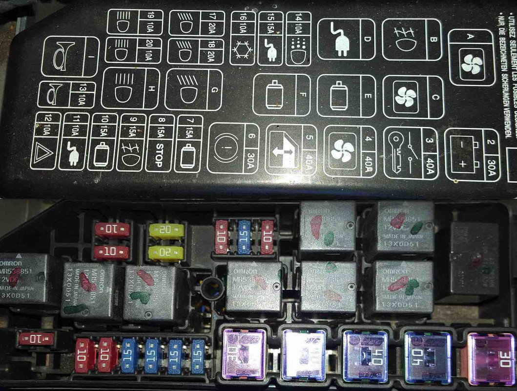
Ok. Following on from removing all the fuses in the internal and under bonnet housings, and cleaning the contacts, and re-inserting them, Nothing has worked. Also removed copious multiway connectors, and sprayed contact cleaner liberally about. Still no joy. So decided to attack the Relays in the under bonnet fusebox. They all seem to be the same type MR538851 12VDC. Had to make a tool to pull them out. There was a small amount of corrosion on the legs, so did the usual cleaning, and re-inserted all 9 of them. Suddenly, the car works. Turned it off, had a cuppa. Turned it on, still works. Drove round the block, turned it off. Went mad and washed it. Turned it on, it still works. Currently off, and will see if it works tomorrow. Fingers crossed. 
Wow that's great news!--it sounds like your perseverance has paid off. Did all the relays have some corrosion, or was it only one or a few. It would be great if the culprit could be identified, but that would just be a bonus on top of getting it running.
BlindMoose
Active member

Finally, my i-miev is back. It was strange to drive it after almost 6 months.
Unfortunately, we did not find the cause of the problem. As they were not able to diagnose where the problem was, we agreed on a temporary solution. They added additional resistance of 2.7M to the hybrid board. And the car drives and I also succeeded to charge it using fast charge and at home.
It seems that an error occurs if MCU measured voltage is lower, the system triggers P1A15 error. If MCU voltage is higher, there is no error message. As such a case is impossible, the system has no rule of dealing with it.
When I have taken MCU out, I did not drain the cooling liquid. I took rubber hosings off and taken the unit out. So I drained only 0,3L of cooling liquid. But there should be some air trapped in the system. How should I bleed the air from it?
Also very good news about the replacement board. I hope it will be available.
That is how Sidemips got his car working again too,
http://myimiev.com/forum/viewtopic.php?f=23&t=4225&hilit=No+Ready+P1A15&start=40#p40858
At least there is this work around even though we don't know why or what is causing the issue.
According to the FSM, the P1A15 is thrown related to the timing of the voltage rise:
http://myimiev.com/forum/viewtopic.php?f=23&t=4225&hilit=No+Ready+P1A15&start=40#p40858
At least there is this work around even though we don't know why or what is causing the issue.
According to the FSM, the P1A15 is thrown related to the timing of the voltage rise:
but we really don't know for sure if it is a voltage level or time fault, and the FSM diagnostics does not dig as deep into the circuits as we do.The high-voltage circuit activation and shutdown are controlled by the EV-ECU. The EV-ECU also monitors the voltage of the smooth condenser in the EMCU via the CAN communication.
If the charging time of the smooth condenser in the EMCU reaches the specified time or more, the diagnosis code No. P1A15 will be set.
Similar threads
- Replies
- 19
- Views
- 888
- Replies
- 34
- Views
- 2K
- Replies
- 44
- Views
- 3K


