Not able to drive. P1A15 error.

Mitsubishi i-MiEV Forum

Help Support Mitsubishi i-MiEV Forum:

This site may earn a commission from merchant affiliate links, including eBay, Amazon, and others.
@BlindMoose,

it looks like you are having the same problem, I had in the beginning. I was able to clear P1A15 error and drive further. Even sometimes for several weeks. Then it started to happen every second charging. And finally I am not able to start.
 
@Gencis
You have several CAN buss errors, but i think the P1A15 is real in your case.

The MCU is coded with the VIN number, otherwise it would be somewhat easy to just swap it out with another unit.

The function of the little hybrid isolation measurement board seems to be degrading over time in your case, which is quite puzzling-- what circuit component could behave in such a manner?

In troubleshooting electronics my first look is for burned or charred damage on a board; then for loose or broken connections and solder joints; then i start looking at any capacitors (especially ceramic) involved in the circuit. This finds a high percentage of faults. After all that then a schematic is necessary to get into the details.

i've never heard of one going bad, but maybe the big black capacitor module in the MCU could be degraded? That would be easy to swap out with another and no VIN required. Be careful that no HV is present if you get into that area.
 
@Gencis

After you clear the codes with the scanner, remember to turn the ignition key off. Wait a minute, then turn ignition on. Then when you scan for the fault, it should have been cleared, and should not show as active. Currently, when I clear the fault codes on mine, provided I don't turn the key to start, the faults stay clear. It's only when I turn the key to start that all 4 faults return, and the yellow icar is illuminated, and won't go into ready.
 
@Kiev

Ok phase 1 complete. Negative terminal off battery, back seat removed, metal shield/covers removed. Had all the plugs out. and earth straps off, checked for dirt/corrosion, but none found. No burnt electronics odours either. Fully reassembled all connectors, and earths. Replaced shields, and seat. Disappointed not to find any suspicious components. Phase 2 will be to attack the under steering wheel area.
 
The car occasionally doesn't do anything when turning the key to start. Similar to leaving it in gear, and trying to start. Currently the vehicle only works when I clear the codes, and start the first time. Everything works fine, car drives, everything works, it recently had a new 12v fully charged ancillary battery. Charger works fine. So drive the car, charge the car, use the aircon & heating, all fine. Stop the car turn it off. That's it. Turn ignition on, all fine. turn to start, and Yellow icar fault appears, and won't go, or take a charge. turn off, and turn ignition on, and yellow icar fault comes on and the fuel display slowly clocks up, 1 bar at a time, instead of the usual instant display. Clear the 4 codes again, and the car is as good as new again. To say that this is frustrating, is putting it mildly.
 
Haven't got my own scanner. Borrow 1 from a garage friend (Launch x-341 pro3) I haven't tried 2 start car recently, just gone to ignition on, which is fine. I know that if I try to start @ the moment it will go into fault, so just slowly working my way through every single connector, fuse, etc, trying to find a crappy earth, or corroded terminal. Got another vehicle, so not a problem time wise. The reasoning behind my approach is, in the past I had a Fuel injected Volvo that wouldn't start. Turned out to be a corroded bullet fuse end, for the high pressure fuel pump. Had another that had a SRS fault, and the garage told me it needed new wheel sensors, brake actuator controller etc. Got the car home and traced the fault to an unplugged socket under the back seat. So, if I put the car into a dealership, I expect they will just go through the wholesale process of swapping out perfectly good components, till they eventually arrive at a cure. They haven't got time to be slow and methodical. It maybe I will fail to find anything, and that there is a serious component problem. However, I find that hard to comprehend, as if the fault codes are removed from the car computer, everything is fine. Daft.
 
Sounds like a good approach to me, especially considering all the labor/shop time expense to inspect, clean and verify electrical connections and wiring.
 
It is on the right hand side.

You can verify this by lifting the carpet and lid of the rear compartment and reading the labels on the boxes. The left hand box is the OBC/DCDC made by Nichicon. And the right hand box is the MCU made by Meiden.
 
To Kiev: Thank you.
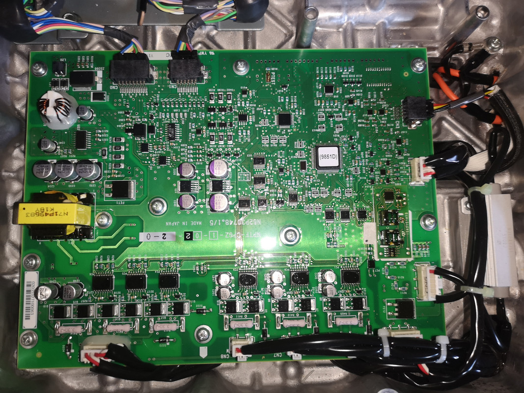
And if I understood from the forum correctly, the MCU board is accessible from the bottom?
 
The control board for the MCU is in the bottom plenum, but i don't know if it is easily accessible from below while installed in the car; it may be easy but i have only worked on these on a workbench after the MCU was removed from the car. But removal has it's own set of issues regarding bleeding air from the coolant lines.

If working on it while in the car, be sure to disconnect the 2 low voltage connectors so no 12V power on the board; and make sure car is off and not charging don't want any HV either.
 
I thought this was an interesting read and, given the technical discussions on the forum, applicable: https://m.slashdot.org/story/385140
 
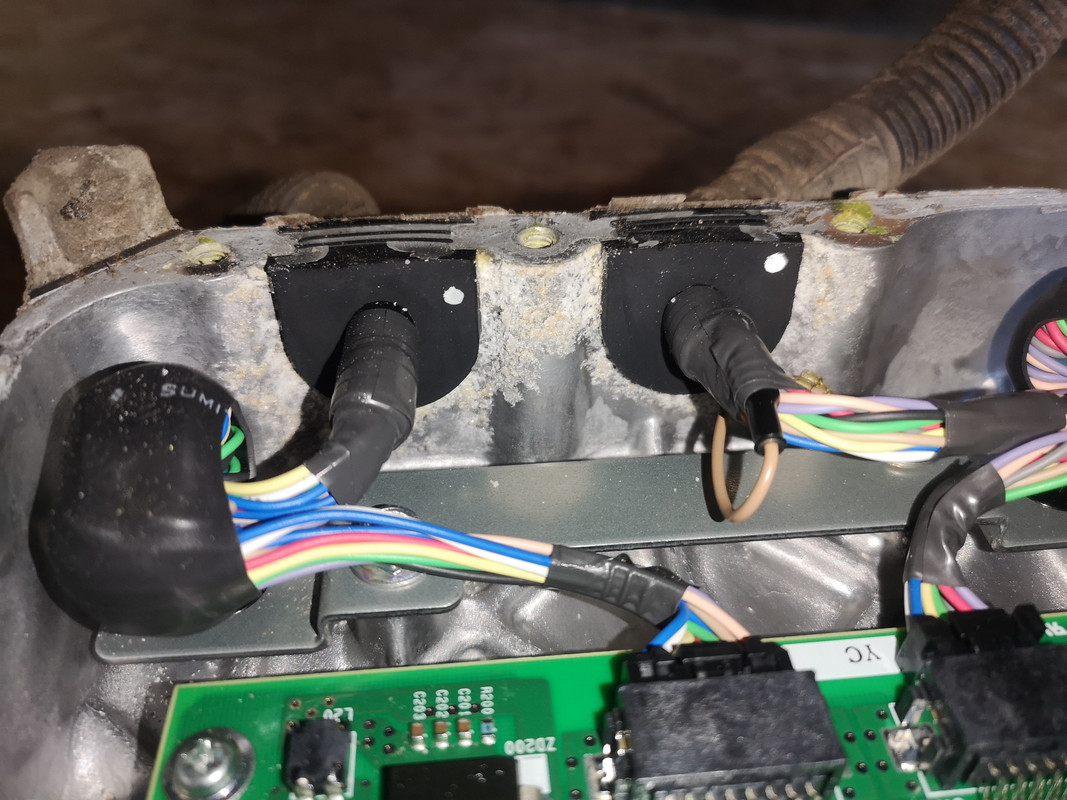
So I have finally taken MCU unit out of the car.
Inside there was some aluminum corrosion at the openings. There was almost no sealant on the cover. It opened very easily.


Inside was some specific smell of electronics. For me, the board has no clear visible damage/loose/burned parts. But I have almost no knowledge of electronics, so all this is a little bit tricky for me.


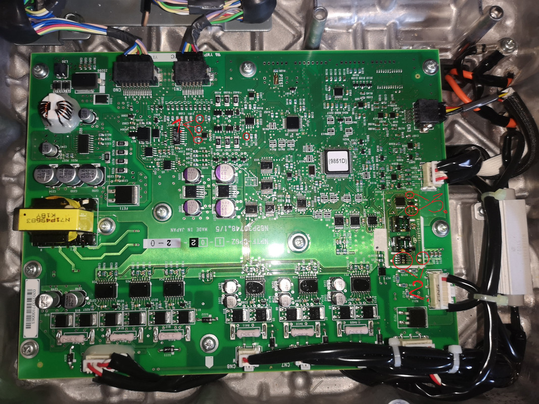
And from forums, I understand that part B21 is responsible for the voltage calculation. Somewhere here is soldering resistors for battery voltage calculation.


What parts should I check when MCU is out of the car?
 
Check the resistance of all the little blue resistors and the resistance from the input posts (VH and VL) to the via near pins 2 and 3 of the op amp on the ISA 215-hybrid board. VH to pin 2 ~100k and VL to pin 3 ~50k. Plus those 3 ceramic capacitors are suspect but would need to be removed from the board to check, then might as well replace them with fresh new ones. An electronics repair shop should be able to check all this for you especially with a schematic.
There is a schematic in this post from page 2 of the P1A15 thread started by Lic. http://myimiev.com/forum/viewtopic.php?f=23&t=4225&start=10#p39208

If no values are found out of spec, then i suspect the hybrid board, but where to buy one? Some folks have tried replacing just the op amp chip marked with date code B21 on your board. B26 on mine.

Bezzeb swapped the op amp
yes, after replacement AD8677 the car started up
but not for long.
As I understand it, the problem is in the capacitors, which, after heating, give an error again
Your P1A15 was an intermittent fault that has progressed to full time, so it appears to be some part degrading over time versus an outright failure. Very difficult to troubleshoot and quite frustrating.
 
To Kiev:
I am preparing the checklist for the electronic workshop. I marked question numbers on the photos. Could you check if I understood correctly?
1. Check the resistance of all the little blue resistors
2. Check resistance from the input posts (VH and VL) to the via near pins 2 and 3 of the operational amplifier on the ISA 215-hybrid board. VH to pin 2 ~100k and VL to pin 3 ~50k.
3. Check 3 ceramic capacitors


Also in any case it would be good to change 3 ceramic capacitors of the hybrid board and operational amplifier B21 with new?
 
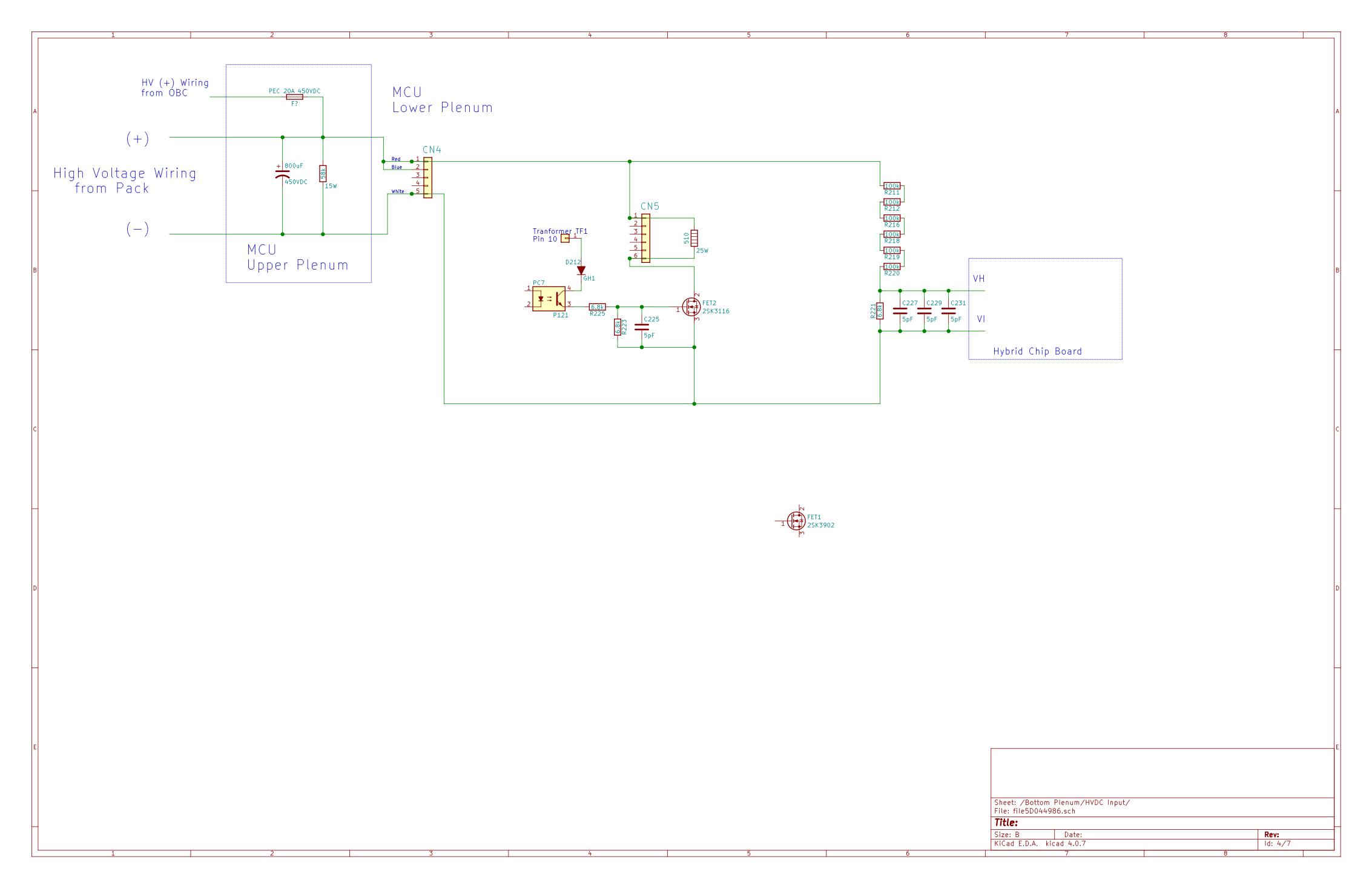
Here is the schematic with the board reference designators for the components in question:
MX7IUyz.png


The blue resistors and 3 ceramic capacitors (each should be about .39uF, not the 5pF default shown on schematic) are part of the voltage divider network on the input side to the hybrid board that drops the pack voltage down to a lower level compatible with the op amp range. Those marked as 1 in your photo are not involved as far as i know.

There is also a bleed-down network in the path shown with FET2. All those parts need to be checked too if possible just to rule out possible fault paths.

There are parts on the bottom side of the ISA hybrid board that could be checked if that board was desoldered from the main board. i don't have a schematic for the hybrid board but it would be worth checking everything that could be measured on it. The next level of diagnostics would be to power up and test the ISA board on the workbench.
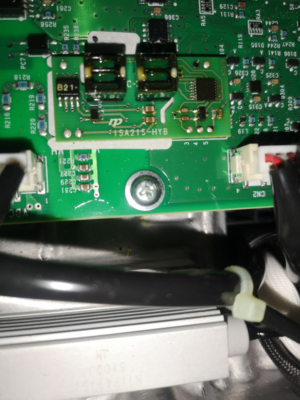
Also on the op amp i measured 100k between pin 6 and pin 2, and 258k between 6 and 3.

If the passive voltage divider network checks out okay, then my guess is the issue is likely on the hybrid board.
 
Back
Top