GregFordyce
Well-known member
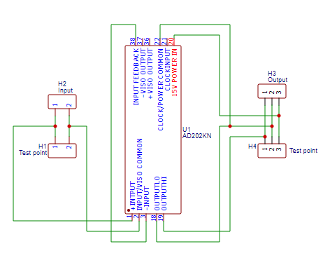
Here's a schematic of the DIP pins to the main PCB connections. The 3 pin connectors on the right labelled pins 1-3 go to pins 3-5 respectively on the main pcb
") Understanding how it worked gave me the info to investigate possible alternatives. The AD202 is marked by the manufacturer as 'unsuitable for new designs' so production may be stopped soon. Ideally a PCB for the AD202KY would be designed. The KY variant stands vertical so the PCB could be mounted parallel to the main circuit board like the original hybrid board is. If AD202KN solution works, is reliable, durable and there is demand, I could design and supply circuit boards for the AD202KY.
Understanding how it worked gave me the info to investigate possible alternatives. The AD202 is marked by the manufacturer as 'unsuitable for new designs' so production may be stopped soon. Ideally a PCB for the AD202KY would be designed. The KY variant stands vertical so the PCB could be mounted parallel to the main circuit board like the original hybrid board is. If AD202KN solution works, is reliable, durable and there is demand, I could design and supply circuit boards for the AD202KY.Gary12345 said:You guys have done some amazing work there!! Especially on the new circuit board that the new voltage measurement package sits on.
I am one of the people with a car with P1A15 - can I buy a circuit board from you?! Will you offer these for sale to help other cars be fixed?
Cheers!
boothegermanshepherd said:...
the voltage is still 6v difference even on regenerate.
The pin spacing is 0.1" or 2.54mm. Those are listed at 1.25mm. I suppose you could solder in the wires at both ends.boothegermanshepherd said:Below are the cables I ordered
https://www.ebay.co.uk/itm/Micro-JST-1-25mm-Connector-Plug-Wire-Cable-Cord-100mm-pcb-mount-socket-/223579971851?mkcid=16&mkevt=1&_trksid=p2349624.m2548.l6249&mkrid=710-127635-2958-0
I wouldn't expect it to. Basically, as I understand it, the BMS reports battery voltage and the MCU reports the voltage it's seeing from the battery via the hybrid board. While it's labelled condenser voltage, as the condenser is connected in parallel to the everything on the high voltage bus, condenser voltage = aircon voltage = heater voltage = OBC voltage = MCU voltage. That's why there are so many things that can cause this fault, anyone of those items can pull the high voltage bus low during precharge and set the error. It would appear that as long as the condenser voltage is within an allowed tolerance (12 volts has been suggested) then you shouldn't have any problems. As I understand it condenser voltage is nothing more than a "dead man's switch", as long as it's reporting within tolerance everything will work fine.Does it change polarity in that the condenser voltage is higher than the pack voltage by 6V during regen?
MCU voltage and pack voltage should always stay the same except for a slight voltage drop due to small resistances in the wires, connections, contactors, etc. On regen the MCU will raise the voltage on the HV bus but it will still be the same at the MCU and battery pack.kiev said:i was thinking that for Regen to occur, then the voltage at the MCU has to be greater than the pack voltage, otherwise no current will flow back to the cells.
I agree with this but on the other hand the board already has a bunch of connectors already, what's 2 more! :shock: I am coming around to the idea of fixing it to the bottom cover with short fly leads. Soldering is more reliable but soldering to the main pcb with 2 connectors hanging down makes access easier. I'll be curious to see if there's enough room for the conectors nest to the AD202 when @boothegermanshepherd builds his....i would want to solder any wires at both ends and not rely on a sliding contact of a pin and socket--a sliding electrical contact is to be avoided whenever possible in my experience.
I'm against this idea because there is the potential for someone to ruin their main PCB board. I believe my hybrid board got ruined by attempts to 'fix' it. When I got my car it had wires coming off the op-amp on the hybrid board running to a switch and resistors. The previous owner said he had got the car to 'ready' and move in his driveway several times. This tells me that the hybrid board was working at that time, but it was completely dead when I got the car. I think the main issue with mine was the contactors in the battery sometimes making a connection and sometimes not. Point is, I would rather have a 6 volt difference that doesn't cause any issue than have someone ruin the main PCB trying to replace that resistorThe easiest way to raise the output to match the pack voltage, if that is what you want, then change the 6.8k on the control board to 6920 Ohm 1% or better resistor. This would bias the input higher such the the AD202 output would be read as equal to the pack.
2x 690k ohm 1% resistors in series = 1.180M ohm. If someone wants to breadboard a working circuit I could add it to the next batch of circuit boards.The gain setting adjustment on the AD202 would involve adding a precision 20k resistor between pins 3 and 4 in the SIP diagram of the datasheet, then a 100pF cap and a precision 1.180 Meg Ohm resistor between pins 3 and 2. A 1.2 Meg is a standard value but maybe the other can be found.
Enter your email address to join: