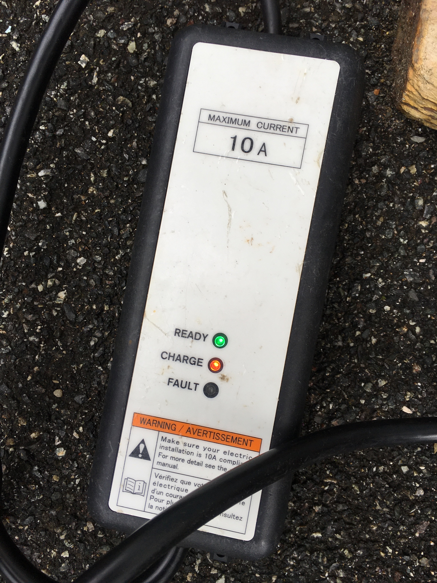
my 2013 Peugeot iOn will not charge :(

Mitsubishi i-MiEV Forum

Help Support Mitsubishi i-MiEV Forum:

This site may earn a commission from merchant affiliate links, including eBay, Amazon, and others.
Fingers crossed it holds. :D

Did you decide to leave the caps exposed or re-pot them ?

I presume the potting is there to keep them still under vibration so if they're not re-potted a blob of glue from the body to the nearby frame might be a good idea..
 
DBMandrake said:
Fingers crossed it holds. :D

Ta :)

I used some squirty silicone conformal coating - though not as deep as the black stuff that was there before.
Not sure I understand why that area is potted, but there are other capacitors on the same board completely exposed.
Could it be a high voltage area?
I may open it up again and get busy with a hot glue gun ;-)
 
i think the primary function of the potted regions, which i sometimes refer to as a doghouse (slang derivative of daughter board, box or housing), are to provide a thermal transfer path for the components within the fence.
 
misterbleepy said:

Seems like same charge cable/EVSE as mine.

Mine will not always charge and I suspect the intake cable is broken. But how do I get of the wires without damage the rubber protection in the intake?
index.php
 
kje said:
Seems like same charge cable/EVSE as mine.

Mine will not always charge and I suspect the intake cable is broken. But how do I get of the wires without damage the rubber protection in the intake?
index.php
I can't get to that link without a login, and my Norwegian isn't good enough for me to register for a userid.
There must be a way to take these apart and get them back together without breaking them, but I don't know how.
Maybe someone else on here has?
 
Well, it looks like I am the next victim of this onboard charger scurge. :(

My 2011 Ion at 59k miles has also had the onboard charger and DC/DC converter both stop working, and I'm piggybacking on this thread because I think (hope ?) my symptoms are a close match for mrbleepy's car.

I plugged the car in to charge on Friday night at about 25% state of charge, the car was not used on Saturday (so remained plugged in) and I then went to use it today on Sunday.

I'm clearly not very observant because I had driven 100 metres up the road before I noticed that I was only at about 70% SoC and had both the low 12 volt battery warning and electric vehicle warning light (yellow car with exclamation) on. Bugger! I turned right around and went back home and took the other car out for the day.

So the car still starts and drives, however the 12v battery is not being charged, so was measuring about 11.9 volts when I checked it with the car in READY - so clearly the DC / DC converter is not charging the 12v battery. I tried plugging the car in to charge and the battery pack fan blows briefly but it the gives up. I haven't tried Chademo charging.

Unlike many of those suffering with this problem I have a Diagbox system so I can get full fault codes and this is what I see:

OBC
02 - Charge fault (traction battery disconnected)
43 - Fault - electrical current too high in the inverter

When I first checked fault codes only code 43 was present, fault 02 didn't appear until after I attempted to charge the car.

BMU
P1A4B - Battery cells fault

EV_ECU
P1B31 - Brake fluid pressure sensor fault
P0A09 - Converter fault
P1A12 - Vehicle charging fault
P1A2F - Fault in the functioning of the cells of the traction battery

So I think it's pretty likely that the 20A fuse in the MCU (?) has blown causing both charging and DC/DC converter functions to stop. What remains to be seen is what else blew first to take out the fuse. Just the caps like mrbleepy would be nice, but from memory there are some resistors that can fail as well ?

Interestingly, I think my specific failure lends more weight to the "capacitors go short circuit first and then blow the fuse" theory because the car charged all the way from 25% to about 70% then spontaneously failed at that point, several hours into the charge. It didn't fail on charge start or due to an interruption to charging. (We don't get power cuts)

Also OBC code 43 tends to suggest a genuine over current situation (though the shorted capacitors) blew the fuse rather than fuse mechanical fatigue.

I'm pretty sure the fault codes relating to traction battery cells are bogus - Canion reports 68% SoC, cell voltages are well matched, all CMU's are reporting cell voltages and the car still drives.

Unfortunately this failure has happened at a very awkward time even if I can fix it, as the yearly MOT is due in under 4 weeks, also I was on the verge of replacing the car with a Nissan Leaf, and may have been using it as a part exchange and at the very least it was being sold to get some money back. If I can't fix it for a reasonable cost it will have to be sold for scrap! :(

What's my best course of action to try to fix this ASAP ? I'm inclined to order the fuse, caps and resistors immediately before even attempting to take the unit apart to minimise delays as time is really of the essence if I'm to get it fixed in time for the MOT.

Is the fuse only available through Mitsubishi or can it be ordered elsewhere ? I've had no dealings with Mitsubishi before. Also I don't suppose you have the details of where you ordered the caps from mrbleepy ?

As far as disassembly goes, I presume initially the best action is to remove the safety link plug under the seat then remove the top of both MCU and OBC to have a look at the fuse and caps ?

I put an intelligent 12v battery charger onto the 12v battery as soon as I noticed the fault, so I think I caught that before it discharged too much, and the traction battery is at about 70% which through luck is an ideal SoC for the car to sit unused for a few weeks.

One other question - when I do remove the OBC completely to replace the caps and check for other faults, what type of coolant is used in the cooling system for on board charger etc, and is there a specific refilling and bleeding process ? I think Diagbox has an actuator test mode that can turn on the coolant pump manually.

I've been following this onboard charger problem on the forum on and off for over a year and been dreading having it happen to me, but just as I was about to sell the car it has finally caught up with me...
 
What a shame, such rotten timing. But you have more tools than most to access and clear fault codes.

i made a repair with the OBC in the car, no need to remove anything unless you can't get a soldering iron out to the car.

The fuse and HV snubber caps can be found at Mouser, but to get the car working and driving until they come in you could just use a jumper to replace the fuse. The MCU fuse only provides protection for the short piece of cable between the OBC and the MCU. i drove my car using a jumper wire in place of the fuse until taking it in for OBC replacement. The jumper will allow the DCDC converter to recharge the aux battery. It's all in your comfort level versus risk management.

i bought a 30A 450V Littlefuse, 0HEV030.ZXISO (plus several other which were xrayed to examine the internal construction, pictures in the OBC thread).

The reason i believe the MCU fuse mechanically fails first is that there is a smaller 20A fuse on the OBC output between the snubber caps and the MCU fuse, which has never blown in anyone's OBC or MCU fuse failure.

Over time, the shock and vibrations while driving caused mechanical fatigue of the tiny thin copper fuse element seen in the xray photos which caused an open circuit situation that resulted in a very high inductive voltage spike that punched thru the snubber caps. This is the simplest explanation that covers all the damage and lack of damage found in most failures. There have been a few failures on the AC input side, but that is a different failure mode altogether with different components.

Some folks have replaced the fuse and snubber caps with good success. In my case damage also occurred in the semiconductors in the epoxy-coated waffle plate, which will require a plate transplant to repair.
 
kiev said:
What a shame, such rotten timing. But you have more tools than most to access and clear fault codes.
Yes having a dealer diagnostic tool certainly helps...
i made a repair with the OBC in the car, no need to remove anything unless you can't get a soldering iron out to the car.
I can get a soldering iron to the car no problem the issue is daylight - it's the middle of winter here so by the time I come home during the week it's pitch black so I would be working in the dark and cold outdoors trying to do delicate soldering work. I can certainly pull the covers off though to give it a visual inspection.
The fuse and HV snubber caps can be found at Mouser,
I'm guessing Mouser is a US parts chain as I've never heard of them in the UK. Mrbleepy is also in the UK so hopefully he sees this and lets me know where he ordered his from.
but to get the car working and driving until they come in you could just use a jumper to replace the fuse. The MCU fuse only provides protection for the short piece of cable between the OBC and the MCU. i drove my car using a jumper wire in place of the fuse until taking it in for OBC replacement. The jumper will allow the DCDC converter to recharge the aux battery. It's all in your comfort level versus risk management.
Doesn't that same fuse also pass the charging current from the onboard charger to the traction battery ?
i bought a 30A 450V Littlefuse, 0HEV030.ZXISO (plus several other which were xrayed to examine the internal construction, pictures in the OBC thread).
I found a link in a thread on speakev.com to where Mrbleepy ordered his fuse from so I have ordered two from here, although it may take a week or so for them to arrive:

https://www.amayama.com/en/part/mitsubishi/9499a656

I have another car to drive in the meantime (a petrol guzzler however!) so the only reason I would consider driving it with a jumper wire for the fuse would be to get it to the MOT test and back. However for that to work I would have already had to have replaced the snubber caps first.
Some folks have replaced the fuse and snubber caps with good success. In my case damage also occurred in the semiconductors in the epoxy-coated waffle plate, which will require a plate transplant to repair.
I'm crossing my fingers that it's just the snubber caps and fuse...!
 
Capacitors, fuse (x2) and conformal coating spray on order, caps and spray should be here in a couple of days, fuses look like they may take a week to 10 days or so.

Farnell and Mouser both didn't have the caps in stock (weeks or months until new supplies) but I found them in stock at Radio spares.

Tomorrow night after work if it's not raining I'm going to pull the front seat out to remove the link plug and pull the top covers off both MCU and OBC to have a close look and confirm what the issue is.

Is there any kind of RTV sealant on the top lids that will need replacing afterwards or is it just a regular re-usable gasket or o-ring ?
 
The lids of the boxes under the boot have a sealant type stuff on, its not a gasket. You prise the lid off and it breaks the seal.

Also the orange "fuse" under the passenger seat can be removed without taking the seat out - just push it back as far as it will go and its possible to unbolt the cover and remove the fuse. If you do remove the seat it can put the airbag light on, which then needs resetting to turn it off. Not exactly a major issue but can be an annoyance if you don't have the correct diagnostic tool to do so.

Cheers.
 
Gary12345 said:
The lids of the boxes under the boot have a sealant type stuff on, its not a gasket. You prise the lid off and it breaks the seal.

Also the orange "fuse" under the passenger seat can be removed without taking the seat out - just push it back as far as it will go and its possible to unbolt the cover and remove the fuse. If you do remove the seat it can put the airbag light on, which then needs resetting to turn it off. Not exactly a major issue but can be an annoyance if you don't have the correct diagnostic tool to do so.

Cheers.
Any suggestion of what kind of sealant to use when I'm ready to seal it up again ?

I've had the passenger seat out before when I did the cell swap and I have the diagnostic tool to reset the airbag fault (again) so that's not a problem.

Also with this weather (rain for the next few weeks pretty much) the only way I will be able to work on the units if I tackle the soldering with the OBC still fitted in the car is if I lie inside the car over the folded down back seats - and removing the front passenger seat gives me a LOT more room to work if I do this. :)
 
Blimey thats dedication ! :shock: To be fair when I had the traction battery out of my first i-miev it was dark with a light drizzle and I had got that far I couldn't resist taking the lid off.....

Anyhow i'm honestly not sure what kind of sealant it is, its grey and looks to me like lead sheet sealant but I couldnt say whether that is suitable for electronics applications or not - I would think as you're planning to chop it in then if you get the car working just bolt it up tight and call it job done... Or maybe worry about that if you are able to fix it?

Best of luck with your lying down soldering in the dark !

Cheers.
 
kiev said:
...
The reason i believe the MCU fuse mechanically fails first is that there is a smaller 20A fuse on the OBC output between the snubber caps and the MCU fuse, which has never blown in anyone's OBC or MCU fuse failure.

Over time, the shock and vibrations while driving caused mechanical fatigue of the tiny thin copper fuse element seen in the xray photos which caused an open circuit situation that resulted in a very high inductive voltage spike that punched thru the snubber caps. This is the simplest explanation that covers all the damage and lack of damage found in most failures. ....

This may have been brought up somewhere, but would it be prudent to preemptively replace the MCU fuse before failure ? though I have a 2014 iMiev, supposedly with different OBC.
 
What a shame, such rotten timing. But you have more tools than most to access and clear fault codes.

i made a repair with the OBC in the car, no need to remove anything unless you can't get a soldering iron out to the car.

The fuse and HV snubber caps can be found at Mouser, but to get the car working and driving until they come in you could just use a jumper to replace the fuse. The MCU fuse only provides protection for the short piece of cable between the OBC and the MCU. i drove my car using a jumper wire in place of the fuse until taking it in for OBC replacement. The jumper will allow the DCDC converter to recharge the aux battery. It's all in your comfort level versus risk management.

i bought a 30A 450V Littlefuse, 0HEV030.ZXISO (plus several other which were xrayed to examine the internal construction, pictures in the OBC thread).

The reason i believe the MCU fuse mechanically fails first is that there is a smaller 20A fuse on the OBC output between the snubber caps and the MCU fuse, which has never blown in anyone's OBC or MCU fuse failure.

Over time, the shock and vibrations while driving caused mechanical fatigue of the tiny thin copper fuse element seen in the xray photos which caused an open circuit situation that resulted in a very high inductive voltage spike that punched thru the snubber caps. This is the simplest explanation that covers all the damage and lack of damage found in most failures. There have been a few failures on the AC input side, but that is a different failure mode altogether with different components.

Some folks have replaced the fuse and snubber caps with good success. In my case damage also occurred in the semiconductors in the epoxy-coated waffle plate, which will require a plate transplant to repair.
Hi Kiev I have a 2011 Peugeot on with the P1A15 fault.also the car will not charge slow or fast.the 12 v battery is ok.the voltage measuring board has been changed using a circuit board from Greg using AN202 replacement. Vehicle still does not go into ready mode.i have diagnostic equipment and only fault showing is P1A15.i have disconnected Aircon & heater cable ev battery showing 342v with part charged battery 31 miles on gom.any advise please many thanks chris
 
Howdy Chris,

Unfortunately it sounds like the repair was not successful, otherwise the P1A15 would have cleared. Did you use an AD202? There is not an isolation amplifier AN 202. There are 2 versions of the chip also, and the pcb traces/wiring would have to be modified for one of them.

So what is the full part number (including suffix, etc) of the device that you bought and installed? Was it a real Analog Devices part or possibly a counterfeit?

P1A15 would not prevent charging, but a blown fuse under the cover of the MCU would prevent charging. So check to see if that fuse is blown.

[Edit: started a new thread for Cwp01's issues] https://myimiev.com/threads/2011-pe...harge-problems-cwp01-is-asking-for-help.5571/
 
Last edited:
Back
Top