Main Traction Battery Upgrade i-MiEV

Mitsubishi i-MiEV Forum

Help Support Mitsubishi i-MiEV Forum:

This site may earn a commission from merchant affiliate links, including eBay, Amazon, and others.
What Mickey said!

My code definitely changes the capacity.

The latest version changes it to 83.7Ah

Code:
Stuff
Yes i was quoting a different code.

This is interesting. So by changing the value in that code to whatever number i wish, i can change the capacity? This is with a CAN device between BMU and the car?

There is not reason not to upgrade the car to the latest battery technology, so this is very good. Thanks for your hard work so far
 
This discussion focuses on upgrades to NMC cells which have been around for a while, if you don’t mind me asking, what are you thinking of using instead?
Well the easiest would be the 93ah NMC batteries, I just meant that given the opportunity cost, value and technology advancement in battery technology in over a decade since this car came out, there is no reason to go "back" to the LE50 batteries.

But I have some experience building 18650 battery packs, perhaps I could make bundles of them to replace the current cells?

But I also have 2 toddlers so I dont think I would have time to sit and weld 2700 batteries either :)
 
Hey pebbles,

Wish you luck in this endeavor.

Yes, I used a drimel tool to mill out some plastic so the case didn’t deform when I inserted cells. I used cork spacers to lift the cells to the desired height. Purchased at a hobby store.
Hi Piev I have an Outlander PHEV but looking to something similar in replacing the battery cells.
1) Understand the cork on the bottom to lift the cell up, but why cork on the top of the cell?
2) Aside from height did they the other 2 dimensions fit? My cells are smaller on all 3 dimensions vs the standard LEV40
3) You need the CAN and software because you want the car to see the extra range?
thanks!
1) The cells were 88 mm tall LEV50's are 98mm so I added fillers so the cells would not move around. The are also thinner and so I added felt spacers between cells as well.
2) The length is a few mm longer and I had to use a Dremel tool to remove some of the plastic case so the cells did not distort the plastic case. I could force them in but it tore the blue shrink wrap and made the case bow. (171mm vs 174mm)
3) Yes, you still need to reset the capacity using a MUT3 or some other device. It will only reset to 48Ah. So the bridge allows you to use the 93Ah capacity.

BTW, for anyone following this thread. Attached is our latest version of the Bridge code.
 

Attachments

  • Arduino_19.txt
    10.6 KB · Views: 3
Last edited:
but why cork on the top of the cell?
Also in addition to the spacing concerns, the case of the cells is "hot", and any exposed metal surface can pass huge current if it is shorted out. The sides and bottom have a heat-shrink coating to insulate the cell, but not the top.

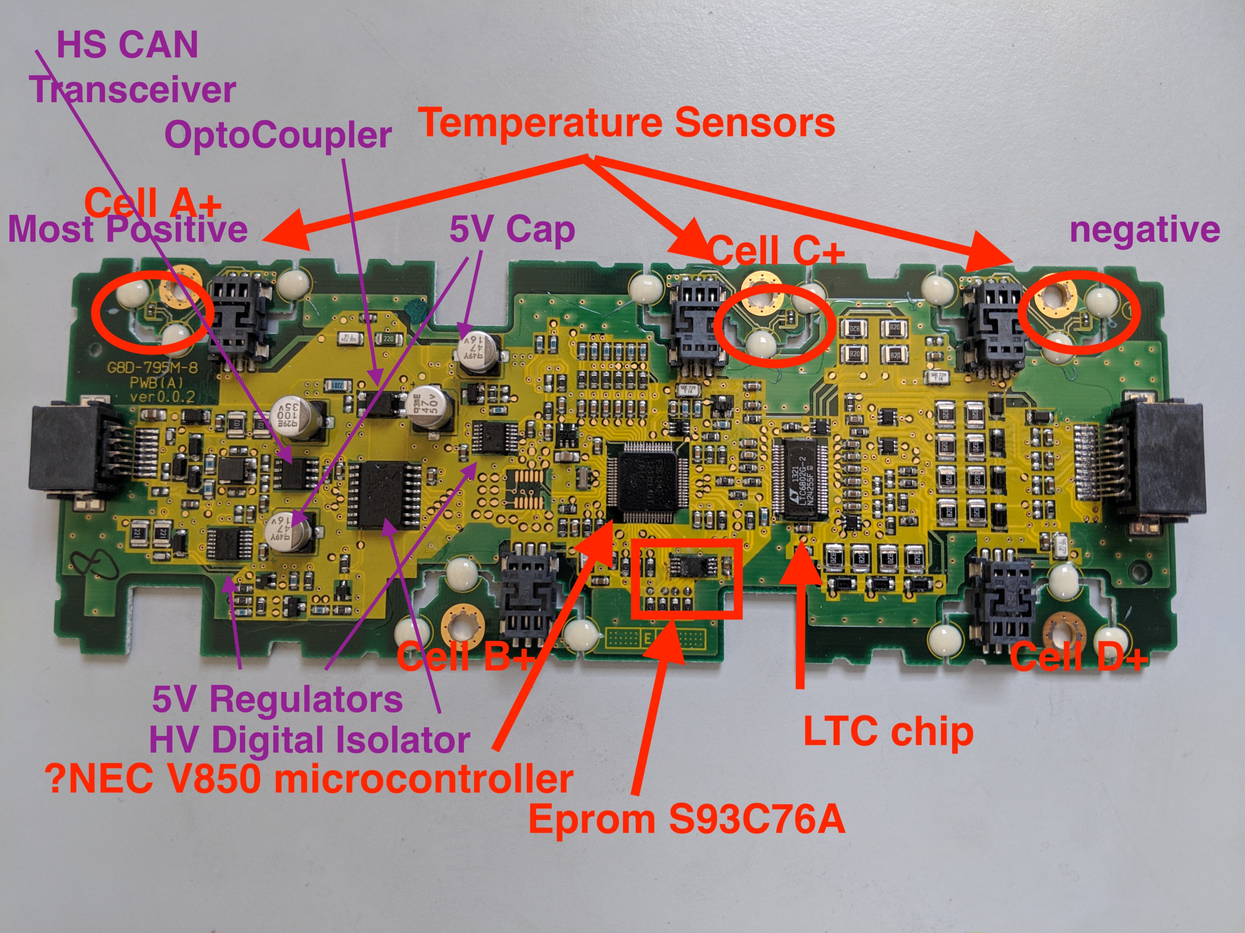
The CMU board "floats" above the top of the LEV cells as the flexible tabs are screwed to raised mounting bosses to read the cell voltage and temperature. Any new cells you find will not have these raised screw mounts, so the bottom of the CMU board needs to be insulated from touching any part of the top of any cell in the modules.

You will have to build some sort of jumper wire to connect the cell terminals to the gold-plated screw holes in the flex tabs of the CMU boards.

7s6JTru.jpg
 
Last edited:
1) The cells were 88 mm tall LEV50's are 98mm so I added fillers so the cells would not move around. The are also thinner and so I added felt spacers between cells as well.
2) The length is a few mm longer and I had to use a Dremel tool to remove some of the plastic case so the cells did not distort the plastic case. I could force them in but it tore the blue shrink wrap and made the case bow. (171mm vs 174mm)
3) Yes, you still need to reset the capacity using a MUT3 or some other device. It will only reset to 48Ah. So the bridge allows you to use the 93Ah capacity.

BTW, for anyone following this thread. Attached is our latest version of the Bridge code.
Thanks for the reply!

2) I am planing on using thermal pads as the spacers, from a tear down video on YouTube I noticed what looks like a t-pad installed from the factory. I plan to use differing thickness T-pads to get me into the mostly correct dimensions. It will be lengthwise that's problematic as I am hoping there's enough flex in the connecting cables to route to the shorter new cells.

3) I have downloaded the MUT3 software and waiting on the VCI dongle so I can test connection to the Outlander. The bridge code is run via MUT3 or something else? I know it was written for imiev but any reason why it would not work on PHEV? I read this thread from the 1st post but there's a lot of gaps in my knowledge right now.

Apologies for the multiple questions while I learn :(
 
Also in addition to the spacing concerns, the case of the cells is "hot", and any exposed metal surface can pass huge current if it is shorted out. The sides and bottom have a heat-shrink coating to insulate the cell, but not the top.

The CMU board "floats" above the top of the LEV cells as the flexible tabs are screwed to raised mounting bosses to read the cell voltage and temperature. Any new cells you find will not have these raised screw mounts, so the bottom of the CMU board needs to be insulated from touching any part of the top of any cell in the modules.

You will have to build some sort of jumper wire to connect the cell terminals to the gold-plated screw holes in the flex tabs of the CMU boards.

7s6JTru.jpg
Hmm thats problematic for me as thats out of my skill set. I can definitely use thermal pads or cork to help with insulation but if I need to MacGyver jumper cables I am out of luck. Was really hoping for a plug'n'play approach with the new cells
 
Hmm thats problematic for me as thats out of my skill set. I can definitely use thermal pads or cork to help with insulation but if I need to MacGyver jumper cables I am out of luck. Was really hoping for a plug'n'play approach with the new cells
It sounds more complicated than it is, see pic below (blue are the new cells).

1720856884573.jpeg
Above ‘cell tab extenders’ were 3D printed but can easily be made out of any (thermally and electrically) conductive material.

More info and images below:
https://www.forums.aeva.asn.au/viewtopic.php?t=5515&start=825
 
It sounds more complicated than it is, see pic below (blue are the new cells).

View attachment 834
Above ‘cell tab extenders’ were 3D printed but can easily be made out of any (thermally and electrically) conductive material.

More info and images below:
https://www.forums.aeva.asn.au/viewtopic.php?t=5515&start=825
Thanks mate, I followed that link and they end up cross referencing this thread at the end ;)

Yep no issues with the spacing of the new cells. I did a spreadsheet to calculate out what thickness thermal pads I would need. Game plan would be to buy a number of sizes so I can adjust if real world is different. If I do it once then I should be able to have a decent stab at making it into a process.

The hard / unknown part is getting the PHEV to see extra range from the larger battery pack.

1720920026482.png
 
Yep no issues with the spacing of the new cells.
What exact cells are you thinking of replacing the LEV40 with?
The hard / unknown part is getting the PHEV to see extra range from the larger battery pack.
Yes, that will require some ‘tweaking’ of the triplet code. But even without a CAN bridge you could reset the battery capacity with your MUT3 and have the original range restored (depending on characteristics of replacement cells)
 
I was wondering if the connection tabs between the Lev50 batteries and the cmu board could be removed to install on the nmc93 batteries? this would be an important step towards plug and play. how are they fixed? Has anyone tried to remove them without destroying them?
 
I was wondering if the connection tabs between the Lev50 batteries and the cmu board could be removed to install on the nmc93 batteries? this would be an important step towards plug and play. how are they fixed? Has anyone tried to remove them without destroying them?
Good point, I tried to pry one off carefully but no luck, found this drawing looks like they are welded on?
1720969925636.jpeg
 
Measured the LEV 50 cell dimensions and picture of the top plates. The case is steel and can be made much thinner than the aluminum cases that are used on most other prismatic cells.

cell_dimensions.jpg

4_group.jpg
 
the definition of the photo does not allow us to see, but would the parts circled in red not be welding points, or rivet points?
The Dremel could tell us more
 

Attachments

  • IMG_20240714_223049.jpg
    IMG_20240714_223049.jpg
    25.3 KB · Views: 1
Last edited:
What exact cells are you thinking of replacing the LEV40 with?

Yes, that will require some ‘tweaking’ of the triplet code. But even without a CAN bridge you could reset the battery capacity with your MUT3 and have the original range restored (depending on characteristics of replacement cells)
I am looking at 90Ah batteries of smaller physical dimensions on all 3 axis.

I am on a PHEV but from what I read it's the same software on MiEV. So hopefully I can recode so it sees the extra mileage, but worse case scenario I move from current 20kms / 15miles up to stock 80kms / 50 miles range.
 
What exact cells are you thinking of replacing the LEV40 with?

Yes, that will require some ‘tweaking’ of the triplet code. But even without a CAN bridge you could reset the battery capacity with your MUT3 and have the original range restored (depending on characteristics of replacement cells)
Hi all, sorry to but in being a newb. I want to also perform this upgrade, I have built booster packs for my various evs with good success and results. I am not afraid of mechanically fastening CMU boards or wiring bms components. what I do struggle with is coding and arduino things, which leads me to ask if there is a thread on the arduino DUE for this application so that I can learn it. are there any boards that I will need to make to implement this CAN bridge? if so where can I find that information? I have read this thread twice trying to find information (which it is full of) for the process, thanks in advance for both constructive and the other feedback that comes my way
 
I am looking at 90Ah batteries of smaller physical dimensions on all 3 axis.

I am on a PHEV but from what I read it's the same software on MiEV. So hopefully I can recode so it sees the extra mileage, but worse case scenario I move from current 20kms / 15miles up to stock 80kms / 50 miles range.
I have 80 2015 LEV40 outlander cells that I recently acquired if you want/need dimensions of the cells before pulling your pack apart
 
Back
Top