Ion 2012. Will not charge AC, only DC. No active codes indicating any useful (after OBC Swap = Yellow car) [Resolved]

Mitsubishi i-MiEV Forum

Help Support Mitsubishi i-MiEV Forum:

This site may earn a commission from merchant affiliate links, including eBay, Amazon, and others.

mwahlgreen

Active member
Joined
Jun 29, 2020
Messages
36
Location
Køge/CPH Denmark
Codes before reset:
U1109 [0xD109]
U1111 [0xD111]
U1116 [0xD116]
U1109 [0xD109] Archive (inactive)
U1111 [0xD111]
U1109 [0xD109] Archive (inactive)
P1A12 [0x1A12] Archive (inactive)

After a reset:
U1116 [0xD116]
U1111 [0xD111]
P1A12 [0x1A12] Archive (inactive)

So I tried to change the OBC to one that should work (caps replaced, never tested)

Now the car gave me the yellow car + ! and no Ready!
Now the only codes showing was
U1111 [0xD111]

The car could not detect the charging cable

Replaced caps in the original OBC and put it back in.
Still yellow car + ! and no Ready!
The car could now detect the charging cable, but no test of anything.

Battery light, !-mark and yellow car stays on in the dash, when key is left for few seconds in ON pos.
(no handbrake activated)

12V battery shows 13.xV and is less than 12 months old (Varta)

Dash shows all "gears", P-R-N-D, when moved and the switch has been sprayed with WD40 as I was in the area.

Main fuse in inverter looks not burned (forgot the measure it)

Any ideas on where to start?


More information + facts

I do not have a MUT II device.
I have an Autel ECS tester. (MaxiCheck MX808)
I also have a OBDLink LX OBD II dongle and an android phone (and an Iphone) with CarScanner & CanIon installed.

I forgot to undo the safety device under the seat+12V battery for one of the swaps, but no key in the ignition at any point, except when trying to read codes with EVERYTHING hook up correctly.

This was Friday (36 hours ago).
I have had a few ideas, that I have not tested yet, however I want your perspective before I muddy the waters with my own.

I also have access to a working car and plenty on old OBC's that just need a new set of caps and one motor controller.

And I really appreciate your help and effort you put in this forum
 
Last edited:
It's unusual to have so many U-codes, which are CAN Buss fault codes.

The P1A12 is thrown for any internal OBC fault for abnormal Stop during charging. The troubleshooting seems to focus on the CAN Buss, and this caution is right up top:
If there is any problem in the CAN bus lines, an incorrect diagnosis code may be set. Prior to this diagnosis, always diagnose the CAN bus lines.

So does the OBC not work due to an internal fault, or because there is a CAN Buss problem (wiring harness damage by rodents, or corrosion of contacts in a connector).

The MCU fuse will not change appearance when it blows--you can't tell by looking at it. This would fail if the snubber capacitors on the HV DC Output section were to blow.

Does the charging sequence seem to fail right at the onset, or does the EVSE relay kick in and the car faults after about 5 seconds?

Since the car will not charge, nor go to READY mode, then the issue is not just about the OBC, but more likely a common cause such as the indicated U-code CAN buss faults.

Pull up the rear seat and inspect wiring and connectors, maybe a mouse has found a way inside.
 
Just to go back to the start, did the car go to READY initially and drove, the only issue was that it didn’t AC charge?

This may seem unrelated, but do your interior (dome) lights work? If not, check fuse #13 as this has prevented AC charging in another instance.

Did you get the DTCs with CarScanner / OBDLink LX on Android, if not try again through the app as iirc someone else had issues getting codes with an Autel
 
...
Just to go back to the start, did the car go to READY initially and drove, the only issue was that it didn’t AC charge?

This may seem unrelated, but do your interior (dome) lights work? If not, check fuse #13 as this has prevented AC charging in another instance.

Did you get the DTCs with CarScanner / OBDLink LX on Android, if not try again through the app as iirc someone else had issues getting codes with an Autel
Yes the car drove in. It would not AC charge.
No snubber cap damage in OBC.

I will run CarScanner and check

I will also check fuses (one of my own ideas)
 
It's unusual to have so many U-codes, which are CAN Buss fault codes.

The P1A12 is thrown for any internal OBC fault for abnormal Stop during charging. The troubleshooting seems to focus on the CAN Buss, and this caution is right up top:


So does the OBC not work due to an internal fault, or because there is a CAN Buss problem (wiring harness damage by rodents, or corrosion of contacts in a connector).

The MCU fuse will not change appearance when it blows--you can't tell by looking at it. This would fail if the snubber capacitors on the HV DC Output section were to blow.

Does the charging sequence seem to fail right at the onset, or does the EVSE relay kick in and the car faults after about 5 seconds?

Since the car will not charge, nor go to READY mode, then the issue is not just about the OBC, but more likely a common cause such as the indicated U-code CAN buss faults.

Pull up the rear seat and inspect wiring and connectors, maybe a mouse has found a way inside.
I will defently measure the HV main fuse. No snubber cap damaged when inspected and changed.

I will take a look at the wireharness for the grey connector again (the connector has been cleaned with contact clean er)

And check for damaged wireharness under the seat.

Cannot remember what the EVSE relay is. However the car does nothing but blinking in the dash. No test of pumps or fans as if the issue where the snubber caps in the OBC. (5 second of "charge")
 
The 5-second time-out is usually due to a failure in the AC Input section.

The session will start with normal pump and contactor clacking noises, and the relay in the EVSE will click ON to supply AC to the car, but the OBC will not detect that AC has made it to the waffle plate.

Your earlier post indicated "no Ready!", so while it may have been driven in, it now won't go to READY, correct?

That's due to the U-codes, there is a fault in the CAN buss somewhere that will block driving or charging. The problem is bigger than just the OBC.
 
Last edited:
Correct, it would go into ready on its way in

No clanking sounds, yes niether main contactors or EVSE relay

I am on my way to dig futher into the wireharness, that migth be the issue

I suspect the gray connector to the OBC on wireharness or a wire full of water ingress (corrosion).
 
You did not (IIRC) mention clearing any DTCs again after installing the replacement OBC…? They will still be active preventing ‘ready’ and charging if they are not cleared despite the ‘new’ OBC.
 
You did not (IIRC) mention clearing any DTCs again after installing the replacement OBC…? They will still be active preventing ‘ready’ and charging if they are not cleared despite the ‘new’ OBC.
Sorry it is not that clear.
I got the yellow car as I was trying to get to ready mode for clearing the codes... As I got the yellow car, I cleared the codes (and have done so many times afterwards.) and still have U1111
 
Update from Monday:
(New questions a later post)
I opened up under the seat. No damage or signs of rodents (wow I did not remember being down here before!)
I then glued my two newly installed caps in the OBC... I found I forgot to tighten a few screws in there, the two orange connections (AC power for something - UPS!). Everything was connected as it should be, but was not tied down properly.
I checked the A13 fuse and cabin dome light = No faults there
I measured MCU fuse = OK

I ran out of time

The next day/evening I shut off the 12V system and went through all the fuses under the steering column, all the fuses in front compartment and pulled all the relays in the front department.
I did not have a relay tester (what is that?), but I just checked all the relays in the front compartment, that they all could come out and go in again (with good contact).
I cleared codes again, no luck.
Shut off 12V again.

I then went to open up the gray connector at the OBC, no sign of damage or corrosion.
I did not take out each wire of the connector and inspect them, but I could have.
I then ran out of time again.

I did not expect to find any faults on any or many of these steps, since I have had no contact that suggests otherwise.

I forgot to try to clear codes with my OBDlink dongle.

I will be back at it at Saturday afternoon.

And just to clarify: I have access to a Autel MaxiDAS DS708 (PRO) and a newer one (which I am not familiar with using). And to a MaxiCheck MX808 as first stated
 
Last edited:
New questions.
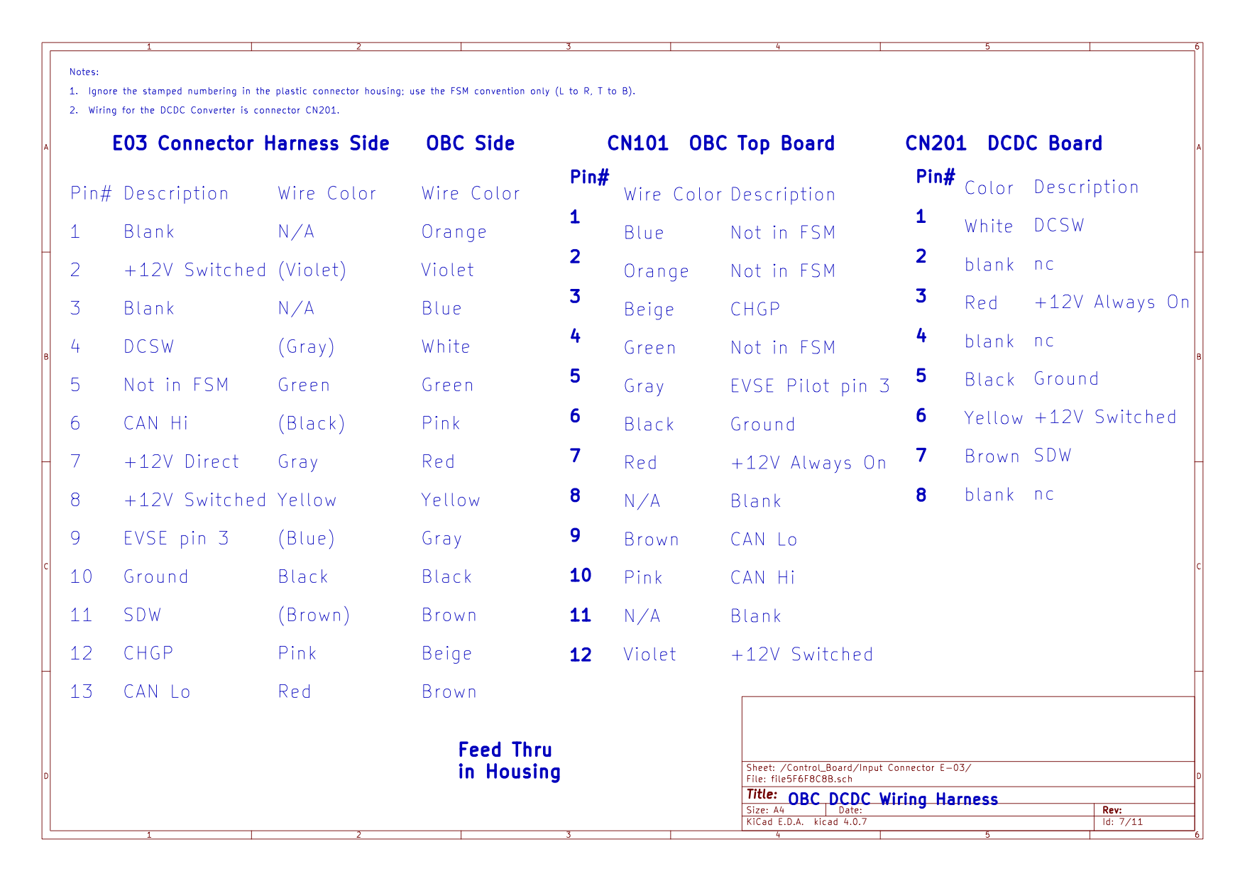
I know there is a wire diagram to be found somewhere here in the forum, or at least a link to one, but I forgot what I need to search for to find it.

Can anyone give me a pinout for the grey connector at the OBC? I would be glad to have a pinout with color codes for the wires in that connector.
(I cannot remember the connector number for this one.)

I would also appreciate some kind of identification to where "pin 1" is on the back of the connector and/or the front. The connector is not in the best place, for me to be able to read small numbers on the housing.

Can I have damaged a CAN transceiver in any device, while I have been working on the car?

Where can I access the CAN-bus for measurements (resistens check), without breaking the loop of the bus?

If I break open the bus, by disconnecting the gray connector on the OBC, have I then removed one of the buses terminators (120 ohm resistor) and cannot expect 60 ohm on the bus?

I may have more questions, but that is all I have come up with and that I can remember.
 
There is a dedicated thread for the Troubleshooting and Repair of the OBC, with an index and links to all the internal circuits, plus the wiring diagram for the gray connector.

https://myimiev.com/threads/the-tro...r-on-board-charger-obc-thread.4079/post-49885

Do a search for the E-03 connector, then there is a link in the index to the diagram. Found it,
dc615a8619a8478ccaa9cbd29846cdff.png
 
Last edited:
New questions.
I know there is a wire diagram to be found somewhere here in the forum, or at least a link to one, but I forgot what I need to search for to find it.

Can anyone give me a pinout for the grey connector at the OBC? I would be glad to have a pinout with color codes for the wires in that connector.
(I cannot remember the connector number for this one.)

I would also appreciate some kind of identification to where "pin 1" is on the back of the connector and/or the front. The connector is not in the best place, for me to be able to read small numbers on the housing.
Have a look here, section 90 Circuit Diagrams
http://mmc-manuals.ru/manuals/i-miev/online/Service_Manual/2017/index_M1.htm
Can I have damaged a CAN transceiver in any device, while I have been working on the car?
That’s a real possibility given that your worse off now then when you started
Where can I access the CAN-bus for measurements (resistens check), without breaking the loop of the bus?

If I break open the bus, by disconnecting the gray connector on the OBC, have I then removed one of the buses terminators (120 ohm resistor) and cannot expect 60 ohm on the bus?

I may have more questions, but that is all I have come up with and that I can remember.
See link above
In a bus system all nodes are connected in parallel, the 120Ohm resistors are at each end of the bus.
 
Update!

I need to come to a conclusion.

Thank you guys for helping my through this...

I fixed the bad boy... It is alive AND it is CHARGING via AC again.

I did a last stretch attempt today. And it worked.

I did as Mickey suggested and looked through the maintenance manual, however, I did not follow his lead fully.

I went into the section for troubleshooting CAN busses instead of directly looking into the diagrams.
This lead me to the locations of various connectors around the car...
So I tested voltage difference to the frame on al CAN busses in C-103 and B-24 (as suggested by the guide)
(I skipped B-20, since I could not lift the car to access connector (B-317) on HV battery pack)
I also tested for resistance between each CAN L & H, and found the two terminators to be around 124 Ohm and 104 Ohm in both connectors, same bus.
Note: All the wires in C-103, was not at the right place according to the manual... However all the CAN L was in low section of numbered pins and all CAN H was in the high section of numbered pins, so it did not matter.

None of the above showed me anything, just that the fault had to be in the OBC or the EV-ECU ;(

Now I picked up my OBD dongle in my Zoe (where it has moved to) and read codes... And codes I had...
After shutting of the CAN 2 off completely twice with power on (for testing according to the manual.) I had "everything"...
I did a reset and got U1116 and U1111... those I knew... Sadly not what I was looking for.
(I think the Autel would have done a fine job as well, but I wanted to try my Dongle)

Now back in my mind, something came up... I was planning another fix, but I had forgotten: Disassemble all of E-03 and check every single wire was ok...
So I did... then I went to reset codes... Before I made that far... NO YELLOW car... I jumped into the seat and started the car... EVERYTHING came alive... READY! BING!
Next step... Check that I would charge... The HV pack disconnected the connectors, as soon as I sat the plug in...
No charging, it just kept blinking in the red plug...

I went for removing the key from the ignition... VOLA... Charging sequence started and the red plug lit up... What a beautiful sight.

I secured the wire for E-03 with some zip-ties, so it should see less vibrations and I think I will tell the owner to spray it with Silicon.

Now I am just waiting for the owner to come and pick up the car.

BTW: I do not think the problem had ANYTHING to do with the codes in the first place.

And it is the second time I see a car with damage to E-03 due to weather and age.
Both cars was covered in Dinitrol/PAVA (anti-corrosion wax)
The first one had a broken wire isolation and I ended up sending it for scrap, since I would not be able to source a new wire harness and even replace it...

I will put the subject of this thread, as solved.
 
Back
Top