You are using an out of date browser. It may not display this or other websites correctly.
You should upgrade or use an alternative browser.
You should upgrade or use an alternative browser.
Gen1 DCDC Converter Troubleshooting and Repair
- Thread starter kiev
- Start date


Help Support Mitsubishi i-MiEV Forum:
This site may earn a commission from merchant affiliate
links, including eBay, Amazon, and others.
[edit2] i just used a power supply to put 5V on pin 1 of CN201 and 12V on pin 6 and did not get any current flow thru the Zener diodes, so i'm thinking the "30" means 30. and not 3.0 volts. So now i'm back to thinking the discrete SDW is nominal 12V battery system voltage levels.
[edit1] i never determined the Zener voltage of ZD 202 and 203, both are marked "30", but if that means 3.0 and not 30., then what i wrote here is not correct. Maybe the DCSW and SDW are 5 or 3.3V signal levels?
[/edit]
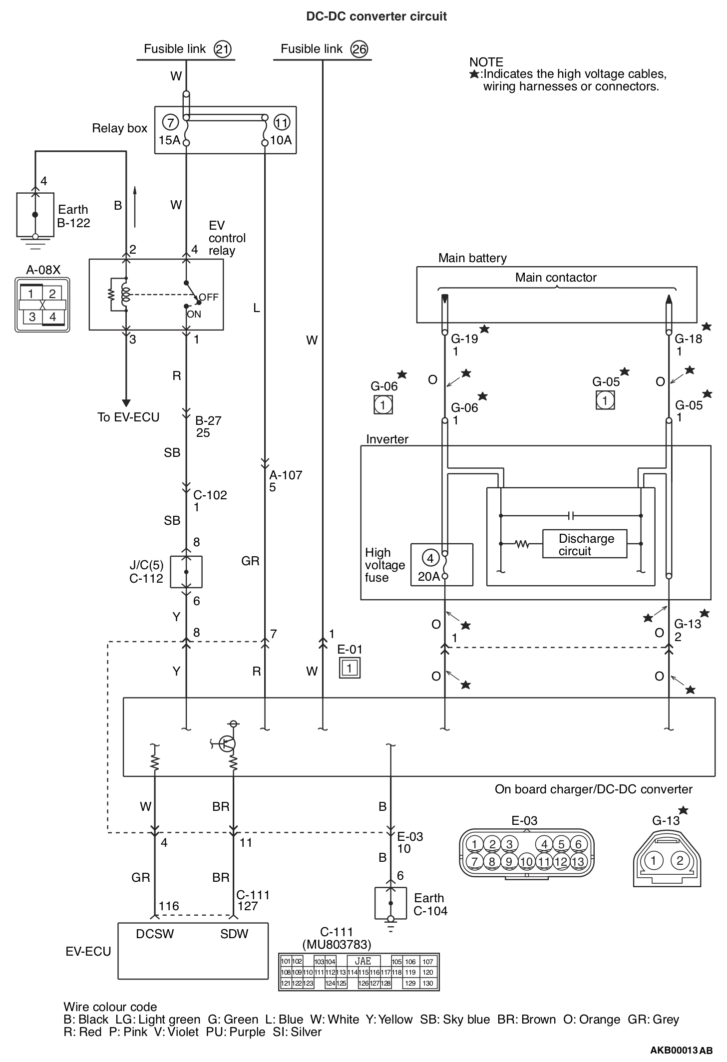
Yes you are right it is battery voltage, i.e. what i was calling the +12V Switched system voltage that comes in on the yellow wire to pin 8 of E03 connector to the OBC, and gets routed down to CN201 connector on the DCDC board pin 6.
This system voltage gets returned on pin 7 "SDW" of CN201 up to the Brown wire of pin 11 in E03 connector to the EV-ECU. This happens when the transistor Q210 is turned ON to complete the path; the drive for Q210 occurs when all the check circuits in the DCDC are "happy".
Not sure what line you are calling a 5V DCDC enable? Is the DCSW a 5V output from the EV-ECU?
This is nearly drawn out in the diagram, just draw a line from the end of pin 8 over to the top of the transistor shown on pin11 of E03.
[edit1] i never determined the Zener voltage of ZD 202 and 203, both are marked "30", but if that means 3.0 and not 30., then what i wrote here is not correct. Maybe the DCSW and SDW are 5 or 3.3V signal levels?
[/edit]
Yes you are right it is battery voltage, i.e. what i was calling the +12V Switched system voltage that comes in on the yellow wire to pin 8 of E03 connector to the OBC, and gets routed down to CN201 connector on the DCDC board pin 6.
This system voltage gets returned on pin 7 "SDW" of CN201 up to the Brown wire of pin 11 in E03 connector to the EV-ECU. This happens when the transistor Q210 is turned ON to complete the path; the drive for Q210 occurs when all the check circuits in the DCDC are "happy".
Not sure what line you are calling a 5V DCDC enable? Is the DCSW a 5V output from the EV-ECU?
This is nearly drawn out in the diagram, just draw a line from the end of pin 8 over to the top of the transistor shown on pin11 of E03.
i've never measured the DCSW signal at pin 116 of the EV-ECU, or at pin 4 of the OBC E03 connector. Has anyone done this?
[edit]
Looking in the FSM, pin 116 is the "DCSW" and listed as the 12V DCDC converter shutdown signal, and the measurement should show battery voltage.
http://mmc-manuals.ru/manuals/i-miev/online/Service_Manual/2012/54/html/M154920100002700ENG.HTM
Pin 127 is the "SDW" and listed as 12V DCDC converter drive signal
Electric motor switch: ON (before electric motor unit start), should read 1 V or less
Electric motor switch: ON → START position (after electric motor unit start), should read Battery voltage.
From my look at the circuit boards and wire colors, i think DCSW is an output of the EV-ECU and SDW is an output of the DCDC.
i wonder if there is a typo or error in the FSM, where DCSW should be the Enable or Drive signal, not the shutdown; and SDW is the Shut Down, not the drive?
Overview of DCDC Converter in the Technical Information Manual,
http://mmc-manuals.ru/manuals/i-miev/online/Service_Manual/2012/54/html/M254950030002900ENG.HTM


$14.99
Built Industrial Adjustable 3 Jaw Oil Filter Wrench with Adapter and Plier Tool Set for Auto Care
Infinite-Commerce


$399.00 ($7.98 / Foot)
$479.00 ($9.58 / Foot)
PRIMECOM Level 2 Electric Vehicle (EV) Charger (220V / 240Volt, 16Amp) Portable EVSE Smart Electric Car Charger, 30', 40', and 50 Feet Lengths (NEMA 14-30P, 50 Feet)
PRIMECOM . TECH


Thank you for the update that is very helpful information for this thread. Good luck on your repairs and getting it all working again.
Thank you to. IDK how many days I would spent trying to make this work, if not your help. And if only I always recheck any connections, it would be faster. So, I may say even more, cos of my "fails"
- No charger connected or half plugged gives battery errors.
- Brown wire to yellow, as dc-dc do gives sometimes error on dash
- Brown wire to red one I don't even tried, cos it may give some errors immediately.
- Brown wire to gnd gives absolutely nothing
- Brown to white gives no errors on dash and no errors in diagnostic software.
Looks like switched +12 and DCSW shows up in the almost same time, but DCSW turns of little earlier than switched +12. Just in case someone will need this information to use i-miev gen1 with another dc-dc or use "stock" dc-dc without i-miev
Can you tell me what material the part where the MOSFETs lay on is made of? (the small plate)Pictures here,
bottom cover of OBC removed, the DCDC is in this lower plenum, only 5 wires to CN201, 450V 20A input fuse, 125V output fuse,
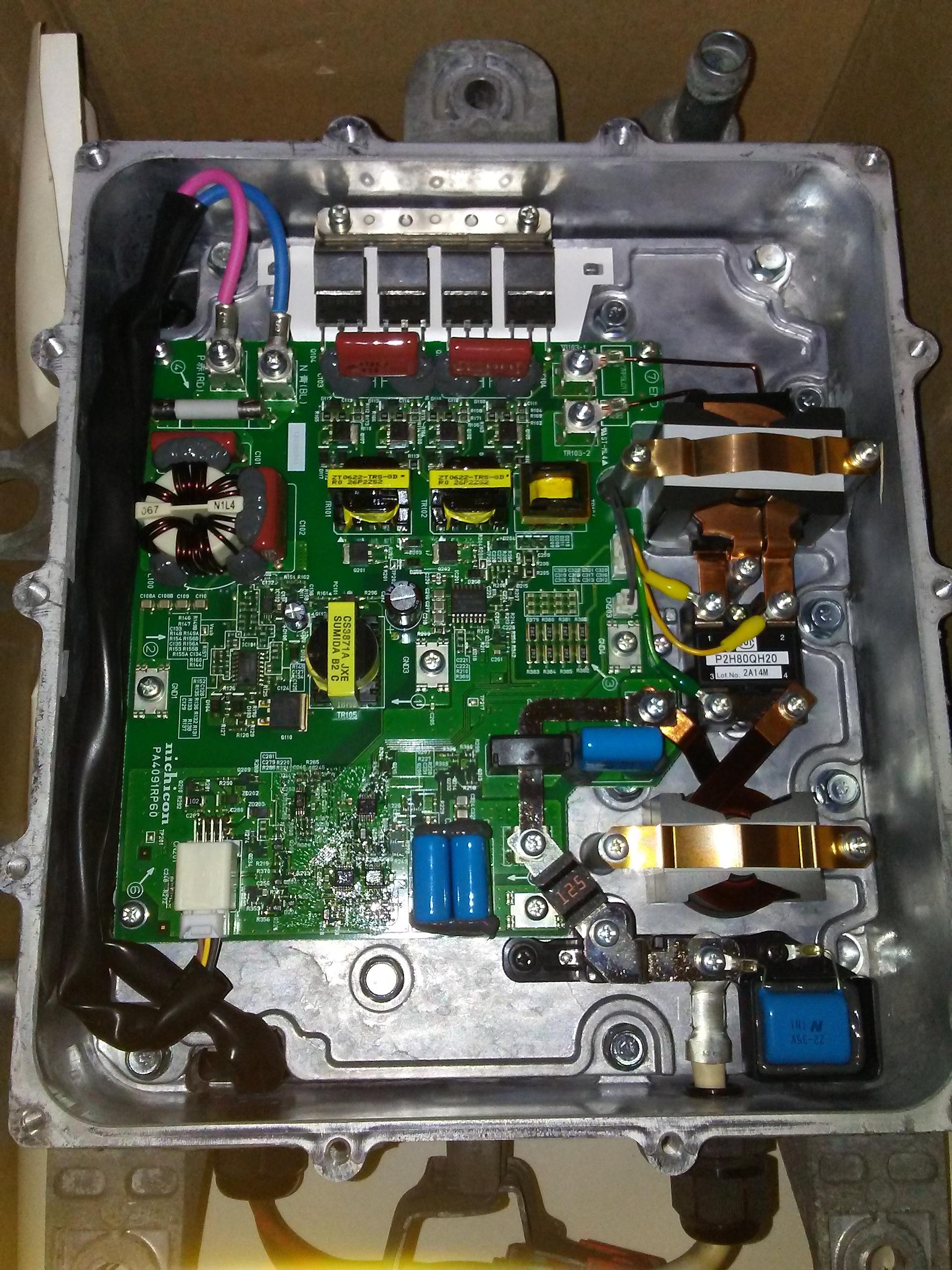
DCDC board removed, MOSFETs are clamped to heatsink for cooling,
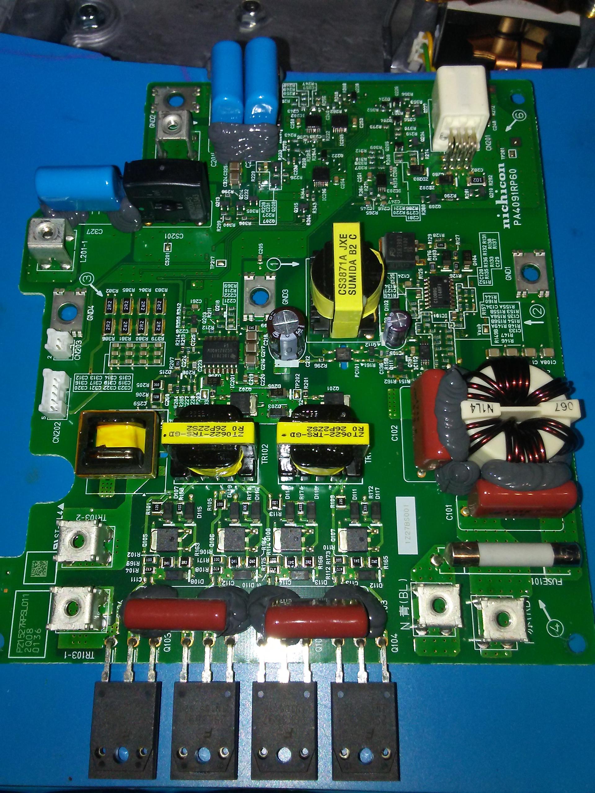
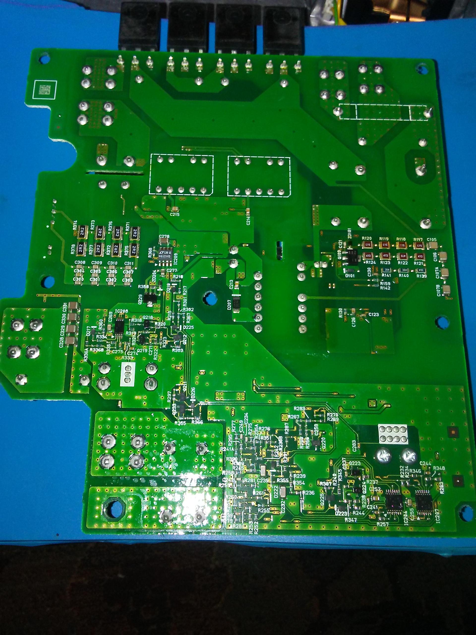
bottom side of the DCDC board, no microcontroller found,
Heat-sinked components attached to cold plate, MOSFETs, Transformer, Diode Module, Output Inductor,
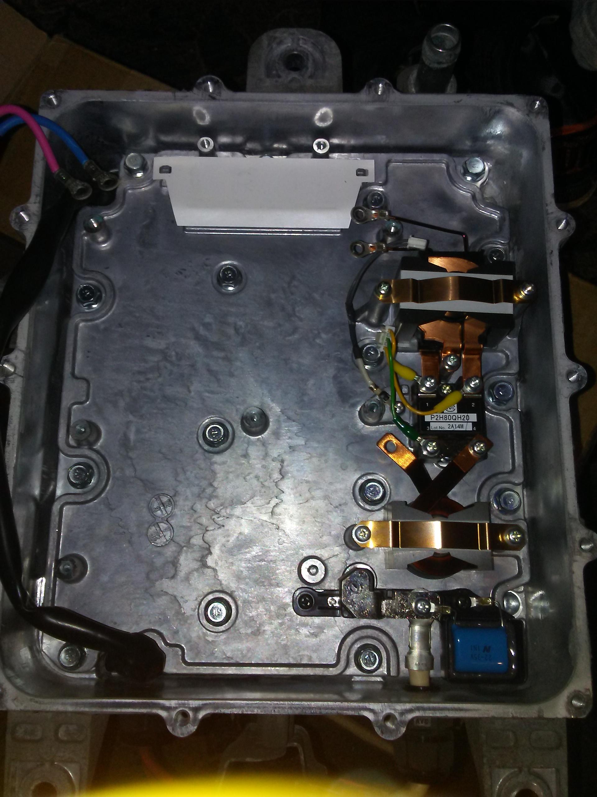
i think it is some sort of cho-therm pad, thermally conductive and electrical isolator, such as found here: cho-therm pads
With some specs here: chotherm 1671
With some specs here: chotherm 1671
Last edited:
Hi, everybody!
Two weeks ago i bought dead Peugeot ION, this marking is plotted only in three place, another place have Mitsubishi)
I have a little experience with electronics, and after two days i found bad connection in CAN bus between BMU and CMU's, fixed it and deleted all DTC. After what my car can drive and charge. But i can't connect with OBC and DCDC modules. I use Launch X431, and when I scan devices OBC module answered, the icon turns green, but I can't read anything from it.
My auxiliary battery is OK, it charge (14.4v) in READY mode and when I connect external charger. I have check all connector from CAN2 to white socket in OBC plate, checked the oscillograms of the CAN signal. From all this, I conclude that the problem is in the CAN on the OBC board.
Do I understand correctly that the DCDC converter does not have a direct connection to the CAN? Can someone help me with the CAN circuit inside the OBC/DCDC module or other advice?
Attachments


Well done on the repair, did you try to connect to the OBC when it’s active (charging)?Do I understand correctly that the DCDC converter does not have a direct connection to the CAN? Can someone help me with the CAN circuit inside the OBC/DCDC module or other advice?
Yes, I connect my charger. When i don't do this, the OBC stayed in Launch in grey color.Well done on the repair, did you try to connect to the OBC when it’s active (charging)?
Ok, you may need a MUT3 or Lexia/Diagbox dealer diagnostics tool to access detailed OBC information. I gather all is in working order and you don’t get any DTC, so why bother?Yes, I connect my charger. When i don't do this, the OBC stayed in Launch in grey color.
Thank fou trying to help me. I can't read eny DTC from OBC/DCDC, but when i connect charger i have many CAN fehler in another blocks. After deleting i can normally drive...up to the next charge))Ok, you may need a MUT3 or Lexia/Diagbox dealer diagnostics tool to access detailed OBC information. I gather all is in working order and you don’t get any DTC, so why bother?
Ok, I see, might be helpful if you post the DCT’s you get when charging.Thank fou trying to help me. I can't read eny DTC from OBC/DCDC, but when i connect charger i have many CAN fehler in another blocks. After deleting i can normally drive...up to the next charge))
Btw you’re right, there is no dedicated DC/DC ECU, it’s all managed by the OBC CAN [Edit, I was mistaken, see @kiev ’s post below]
Last edited:
There is no CAN buss to the DCDC Converter--it is controlled with discrete voltages from the EV-ECU. All DTCs are stored and reported by the EV-ECU. There is a separate thread with schematics and info for troubleshooting the OBC.
Hello Folks! Back with another problem. The 12V DC/DC is not outputting voltage when the car is turned on. Car Check and battery are on when ready. I've made sure the OBC is working after ensuring the 12V battery was charged externally while disconnected. Forgive my ignorance but, any checks I can do before removing the unit out (i.e. fuses, etc)? Thus far, the OBC related fuses in the two fuse boxes check continuity. Haven't open the unit to validate anything else, as the DC/DC is on the bottom. Thanks!
Check for wiring harness damage under the rear seat from the EV-ECU back to the OBC; check for contact terminal corrosion in all the connectors; for example, E-03 at the OBC. Check for continuity of the DCDC command lines from the EV-ECU to E-03 at the OBC.
Maybe insert some needle pins to back probe at the EV-ECU and at E-03 and measure the signal voltages, if the DCDC start command is getting sent out and received.
There are fuses on the DCDC board but not sure that anyone has ever reported blowing one.
Maybe insert some needle pins to back probe at the EV-ECU and at E-03 and measure the signal voltages, if the DCDC start command is getting sent out and received.
There are fuses on the DCDC board but not sure that anyone has ever reported blowing one.
") . Out goes the box for further troubleshooting or swapping.
. Out goes the box for further troubleshooting or swapping.Similar threads
- Replies
- 0
- Views
- 801
- Replies
- 21
- Views
- 2K
- Replies
- 17
- Views
- 1K
- Replies
- 2
- Views
- 991