Ha! I just made a coast/neutral button!

Mitsubishi i-MiEV Forum

Help Support Mitsubishi i-MiEV Forum:

This site may earn a commission from merchant affiliate links, including eBay, Amazon, and others.
kiev said:
Shifting to N while at max regen is probably a dumb move--there is a lot of energy stored up in the rotating magnetic field that will need to be dissipated, and blowing up the MCU would increase operating and repair costs beyond any benefit from this mod...
That *may be* one reason why Mitsu never incorporated anything like this into the car in the first place - If it can't be done without the danger of breaking something under any and all operating circumstances, no doubt they would leave it out

I really like the idea of a coast button, but no doubt in my mind there would be times when we would end up wanting to coast when we were regenning at the time

Don
 
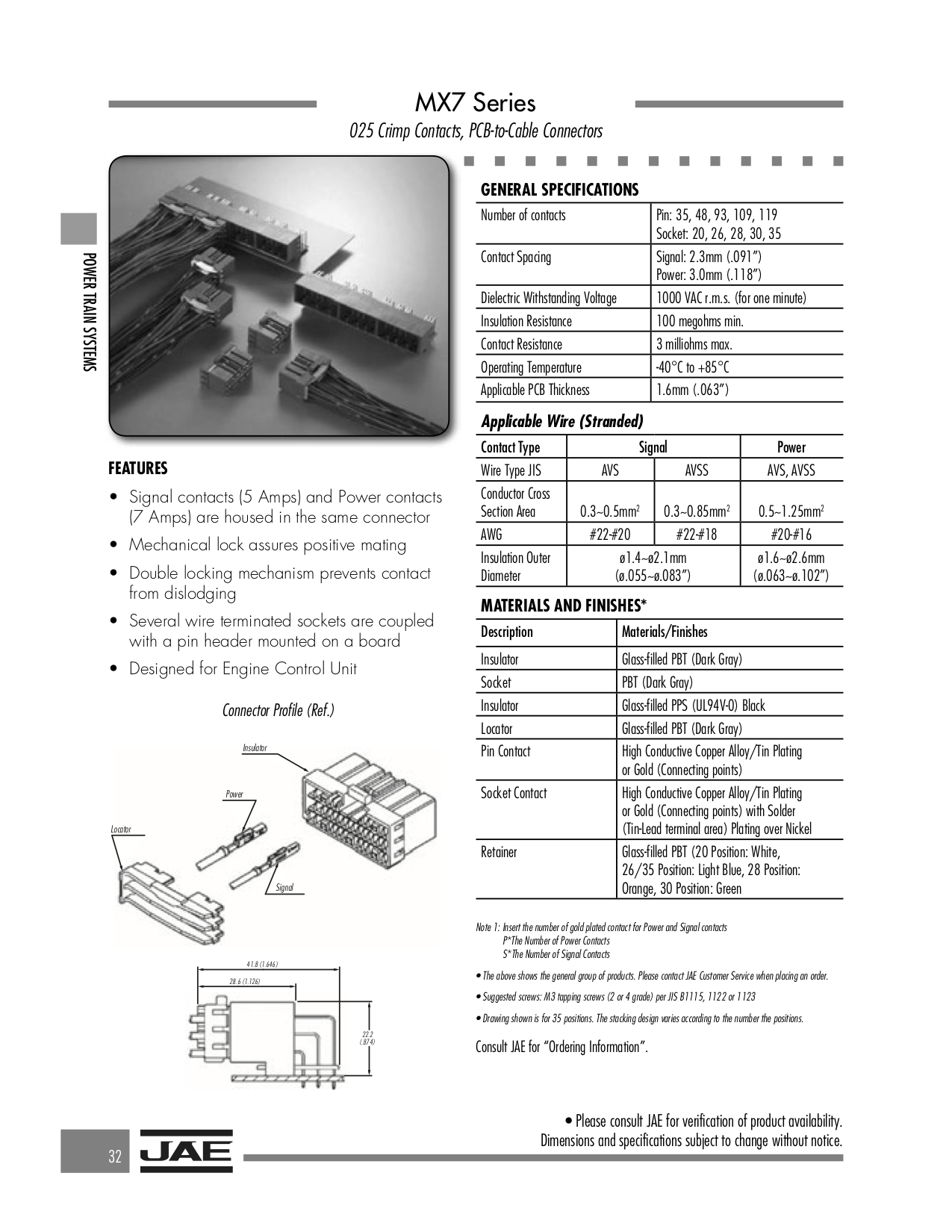
As for the plugs, it doesn't matter if the male side is PCB only. No big deal. To have a board made up just to have the connector on is but a few pennies. Happens all the time in my industry. Either that or cough up ~$2500 to have molds made. Will have to sell a LOT of coast switches to cover that though.
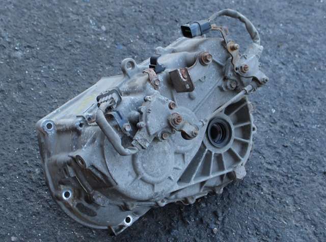
It wasn't the one you circled, but the one on the module itself.

And my harness guys may indeed find them aftermarket somewhere.


I have gone from heavy regen to N and back many times already with my button. I tried it at WOT, full regen and everywhere in between. So far so good. But it indeed may not be healthy in the long run. My normal driving doesn't have me doing that though. If anything I go from coast to heavy regen and not so much the other way around.
 
The plug itself is discontinued from the original manufacturer. But there are indeed a few kicking around here and there. Now to find the PCB side but with only the plug I need and not all of them.
 
Well, JAE never made the single socket for the 28p. They did make a dual though. For that plug and a 20 pin at the same time though. That's better than 100+ pins.

Could probably just cut the 20p off.

Found a couple of places that may actually have stock! We will see if they even reply.
 
I spent some time aggressively driving.

137kmh on the speedo. Lol.

But I was checking this regen-to-coast concern, and I am not concerned in the slightest.

From a max-regen at 75kmh to coast, I felt the transition was extremely smooth and controlled. To me it seems like the car knows what's going on and it is A-ok with it all.

I did this many times, from many speeds. Max regen in B mode, then hit the coast switch. Always the same results.

And for curiosity's sake, I did the opposite. Coast to WOT. Also felt great. Then tried full regen to full throttle.

Kiev - did you switch both pairs of pins? 4 pins total? I'm thinking your problem was not due to your concern.


But for me, heavy regen to coast is a non-issue.
 
@Go

i drove again today and did not have a problem while shifting either direction, B->N, N->B. with and without max regen.

When i had the fault lights, i may have been shifting back and forth numerous times and then accidentally held the shift lever between the gates to cause the EV-ECU to become confused--it then started throwing codes and putting the car in a safe mode. It took me a little while to get used to throwing it forward to hit B from E, and in traffic with redlights i was diddling with the knob instead of putting it in and leaving it in there (that's what she said).

A switch would save wear and tear on the shift sensor sliding contacts and avoid the issue of holding the lever between the gates, so press on regardless of my little incident.

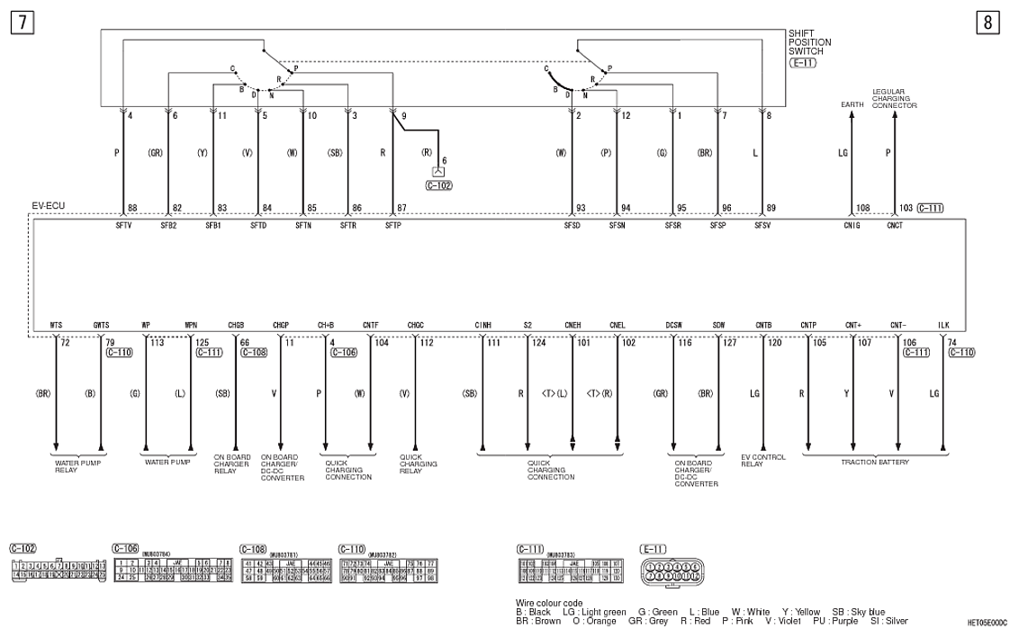
i didn't change the secondary sensor wires since D, E, B are all shown to be connected to the same shift position switch sensor wire to the EV-ECU in the schematic.

Hvjb3Sn.png
 
kiev said:
Shifting to N while at max regen is probably a dumb move--there is a lot of energy stored up in the rotating magnetic field that will need to be dissipated, and blowing up the MCU would increase operating and repair costs beyond any benefit from this mod...

Yes I agree, I do a lot of shifting from D to N and back (mostly on the freeway) as previously discussed. I just naturally smoothed the transitions with throttle positioning. For instance the car seems to have a good controlled ramp if you shift from N into a driving gear. However if you shift from a drive gear to N it seems to just let go. I instinctively zero the needle with the accelerator before sliding the shifter to neutral. Didn't really think about harming the MCU or not. Just like it smoooth ;) I'm sure it is likely best practice though!

Aerowhatt
 
Had written this before Aerowhatt's post...

As someone who has probably spent more time coasting in Neutral than anyone else on this forum (except maybe Aerowhatt), I've been following this N-button discussion with interest, primarily from the hacking standpoint and wondering if it could form the basis for perhaps a better user interface than our clunky shift lever.

The North American shifter layout provides for a gradual decrease in regeneration, with a logical progression going up from B-E-D to Neutral. I do a lot of hilly driving and on downhills (with my foot off the accelerator) I'm constantly modulating my speed using that shift lever, primarily to stay with the flow of traffic. Inasmuch as I try to keep my transitions smooth, I think it would be rare that I would be in B and then would need to instantly jump into N.

The only unexpected response from the car that I've experienced when jumping from N back into one of the other settings has been on long sweeping downhill curves when the road surface gets rough and ASC suddenly kicks the car out regen.

Of greater interest to me has always been the possibility of being able to modulate regeneration using some type of paddle or joystick, but I simply have way too many other projects to take the time to pursue this. Been advocating this concept going back to the Aptera, as well as starting with the early days of this forum.
 
On a 2011 UK MIEV the plug on the EV-ECU under the rear seat is C-110.
I tried without success to release pins 82 and 84 using a 0.026" needle , 0.028" was suggested..
Where is the pin inserted ?
Into the face in the image with the ruler ?
Into the top bar of the "T" ?
Or into the upright of the "T" ?
How far in ?
Which way is "apply slight downward pressure ", towards the metal sockets ?

Help would be appreciated.
 
Thanks kiev, that video helped me to succeed.
Removing the coloured (orange) shroud helped, or was necessary , I'm not sure which.
However I didn't get the desired change in "gear" selection.
According to the Electric Motor Unit Control System diagram part 7:
C is pin 82 Grey
B is pin 83 Blue
D is pin 84 Violet
N is pin 85 Yellow
Swapping D and C gave Neutrals in the wrong places, and the engine light.
So I put it back to normal, all was good again, and I'll leave it like that !
I would have swapped 83/84 to do N<->B but then @kiev was mentioning pin 12 in the picture, can you clarify? Or is wiring different depending on the age of the car?
 
Don't mess with N unless you are doing the push-button mod.

The photo showing socket 12 as the 5th location over on the second row was just to illustrate where N was located. N is designated as Pin 85 of the EV-ECU which counts across all 4 of its connectors.


And yes the 2011 has different wiring than a 2012. That's why folks should put their car info on the profile or signature that shows up when they post. i don't have time to chase around to figure out what model somebody is driving. All my cars are 2012 and that's what i use when i post schematics, unless otherwise stated. Here is the 2011 wiring,

Screenshot 2024-06-04 at 11.42.48 AM.png

And it depends upon which style of shift position sensor(s) is used on the car, which could be two separate ones like this,
OtAFadj.jpg
 
Last edited:
Hi Kenny

" i don't have time to chase around to figure out what model somebody is driving. "
Apologies, I did put "UK 2011" in my first post.
I was using the 2011 wiring diagram.
I hadn't said, I just want the lowest Regen (C) next to N, and highest regen (D) after C and B.
So N - C - B - D

Lightbulb moment, slaps forehead:

I had it fixed in my brain that the sub-switch wiring didn't need altering.
From seeing an image in an earlier post where the sub-switch has C, B, D joined.
So please confirm, now I've prpoerly looked at the 20111 wiring diagram, that I should also be altering pins 89, 81, 92, 93 from the sub switch, as well as 82 to 85 from the main switch ?

Going forward, rather than damaging the locking pins by repeated unlocking, I intend to cut the wires well back from the plugs, crimp on ferrules, and re-attach with Wago-type connectors.
 
Last edited:
Howdy Michael,
Sorry to be old and cranky, and missing that you did post your model year.

You are correct that both sets of sensor inputs at the EV-ECU have to be swapped around to get the shift sequence that you desire. It looks like you just want to swap C with D, so just 4 pins total: 82 with 84, and 81with 93

i found another 2011 wiring diagram in a service bulletin
Screenshot 2024-06-05 at 8.05.17 AM.png
 
2012 diagram definitely had wrong colours, 2011 was correct.
EXCEPT
Pin 93 was sky blue (as correctly was pin 86) instead of orange.
But the swapping by cutting wires and rejoining with Wagos worked.
Many thanks to all who replied.

Next questions.
1. Is the motor connected to the wheels in N, as some posts worried where the regen goes to if the motor is connected when coasting in N ?
2. Is it possible to code the amount of Regen, as I find even C is too much ?
I would rather have zero like the BO paddle on Outlander PHEVs gives.
 
Here's my answers:

1. Yes the motor is always connected to the wheels--it is a direct connection thru the gearbox and differential with no clutch or shifting of gears.

2. Interesting idea but nobody has reported cracking the code. It would seem that some CAN Buss command would control the regen level--did they determine this over on the Outlander site?
 
Back
Top