kiev said:
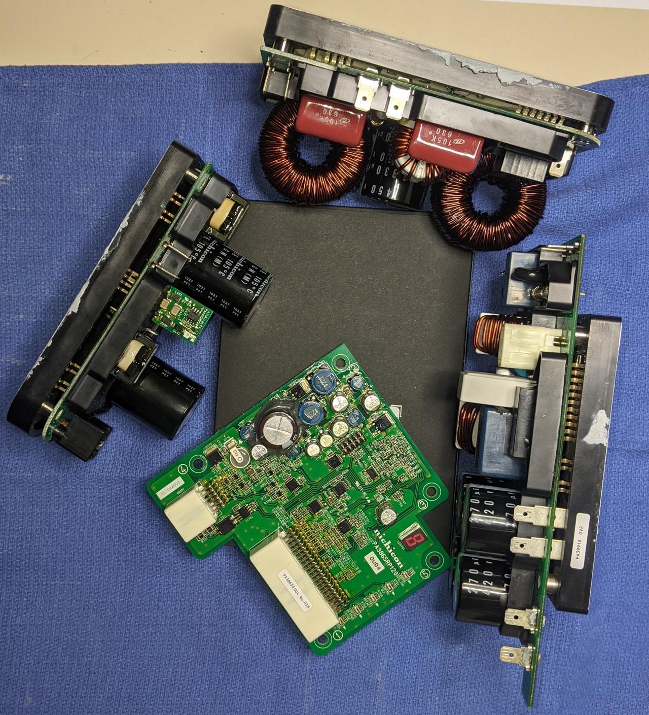
@ coulomb, take a look at Phil's board at the rh end--somehow that circuit looks familiar
It sure does! Thank you so much! I never thought about the other modules and how they get their power for isolated measurements.
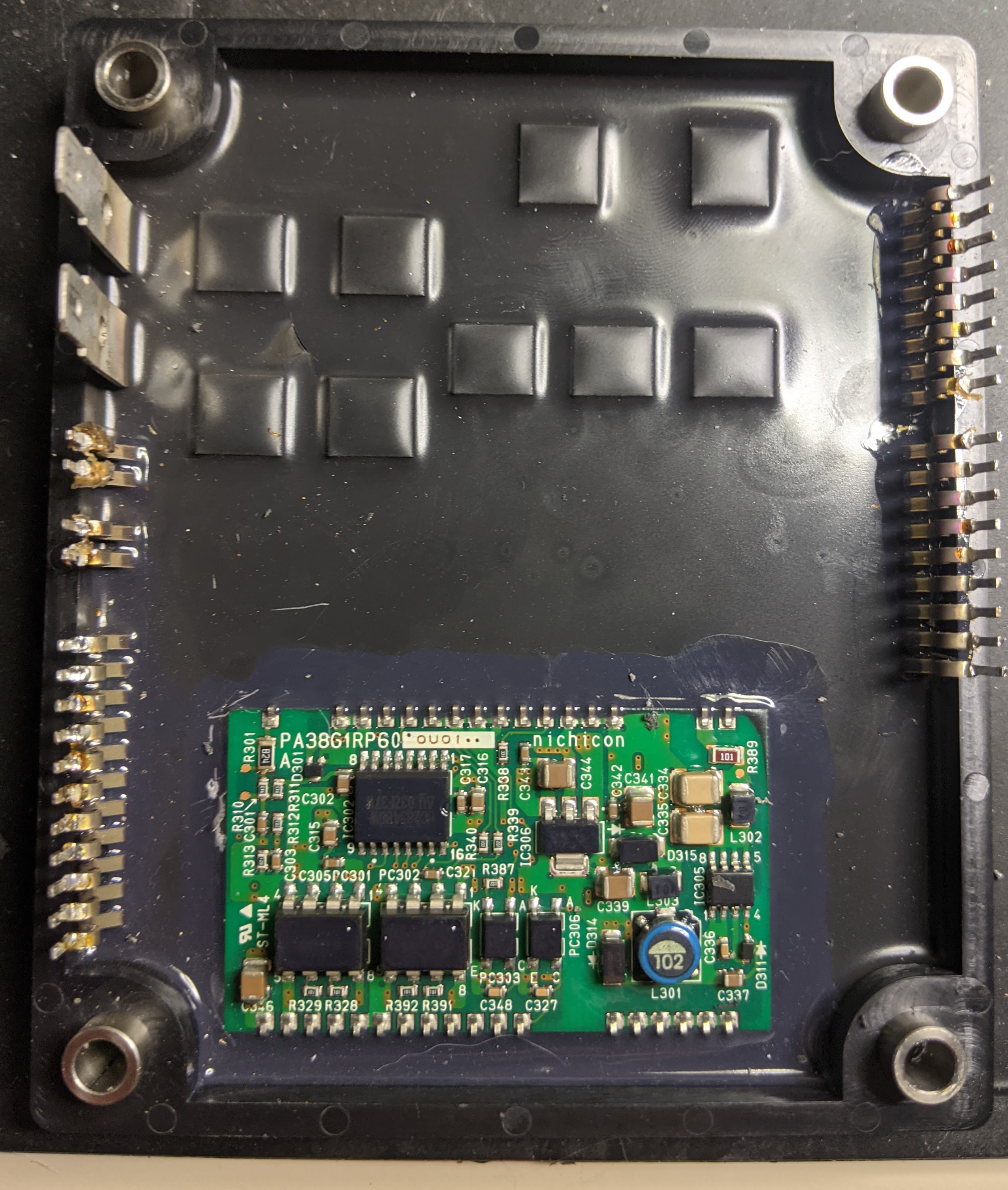
IC305 looks like a Viper,
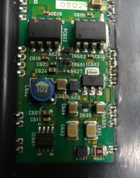
I'm sure it is, with pins 5-8 and 1-2 commoned. And L301 looks identical to L601.
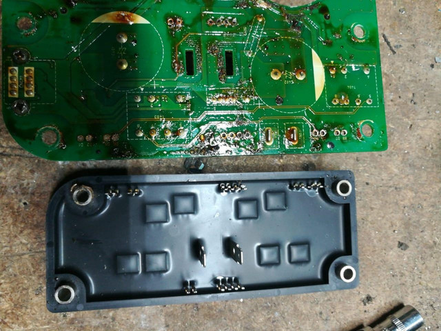
also take a look at D315 or 311 or 314--one of those might be the missing diode on your board?
Yes, D314 looks like it's the "missing" diode, and it appears to be bigger than the ones on the output module. I can't read the marking codes; it
might be K8 or KB on one line and D6 on the one below. Possibly D311 provides the Vcc feed to the Viper, along with the nearby capacitors. If that's all there is to the Vref circuit (pin 3), it's very simple and clean.
But most important of all, the value for R389 is clearly readable! It will hopefully be the equivalent of the blown R601, code 101 = 100Ω. It seems smaller in size to R601, and the clearance for DC arcs is shockingly small, so let's hope that C334 and C335 hold up better than C601 and C602. My guess is that this Viper doesn't run on main battery volage, which is not available in this rectifier module, but rather from rectified mains, which peaks at some 340 V (or half that for 120 V charging), but has a lower RMS value (240 or 120 V). But instead of running all the time when the car is in ready, this will be present only when plugged in for charging, so I'm hopeful that these capacitors will last much longer than their equivalents in the output module. It's something to keep in mind as a potential fault pattern, though, if mains measurement stops working in future repairs.
It looks like this module has two analog measurements, and two digital outputs (via opto couplers PC303 and PC306). IC302 will of course be the PFC chip. I read UC285480W, nothing like the L4981AD PFC chip on the Elcon chargers. I see that the 100Ω resistors between the isolation amplifiers and the outside world are on top of this board (R329 etc). Maybe they were able to fit all the parts on one side of this board.
Thanks so much for your thoughts, Kiev! It validates adding the 150Ω resistor in series with the fuse, though of course @vik013's measurement on a known-good output module would be even better to know.
Edit: here is the direct link to Phil's photo on Imgur: https://i.imgur.com/guRRm5e.jpeg . That makes it easier to try and read marking codes, etc.