You are using an out of date browser. It may not display this or other websites correctly.
You should upgrade or use an alternative browser.
You should upgrade or use an alternative browser.
The Troubleshooting and Repair for On-board Charger (OBC) Thread
- Thread starter kiev
- Start date

Help Support Mitsubishi i-MiEV Forum:
This site may earn a commission from merchant affiliate
links, including eBay, Amazon, and others.
Like Coulomb stated there is likely a much bigger issue. The capacitor was just a symptom of a failure, not the cause. The 5V power supply is suspect and many chips are powered by that buss. There is also a 16V supply and the 12V input voltage lines. There is a fuse on the board that hopefully blew to save the rest--it is shown on your picture at F701.
U111D On board chargger CAN time-out
The CAN buss communicates from the microcontroller to the EV-ECU. The EV-ECU is not getting communication with the OBC and throwing this code.
The simplest solution would be to replace that little upper board completely--swap it out with another unit to see if that solves the DTC error.
318iEV
Member
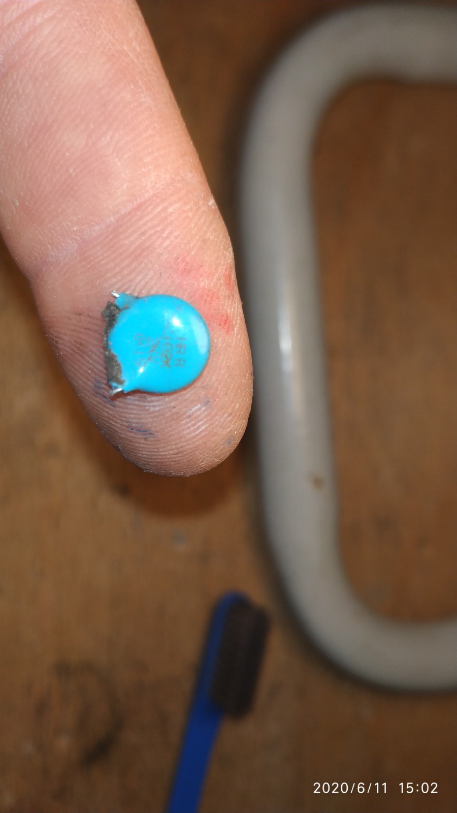
Has anyone ever encountered the OKAYA LE105 capacitor in the potting goo on the top board of the OBC exploding as well as the caps on the bottom board when it fails? I’ve bought the new capacitors and will be hopefully fixing the OBC soon, I thought I’d mention this issue as I haven’t been able to find any other mentions of this specific cap failing.
New top board capacitor:
https://nz.rs-online.com/web/p/polypropylene-film-capacitors/1896834/
Photo:
https://photos.app.goo.gl/18di4AGxAXnmVQfG7
New top board capacitor:
https://nz.rs-online.com/web/p/polypropylene-film-capacitors/1896834/
Photo:
https://photos.app.goo.gl/18di4AGxAXnmVQfG7
That LE105 capacitor on the upper board is in the mains AC input filter circuit.
The snubber capacitors on the bottom board are in the HV DC output section.
Usually it is one or the other that gets damaged, not sure if we have ever heard of both failing in the same OBC.
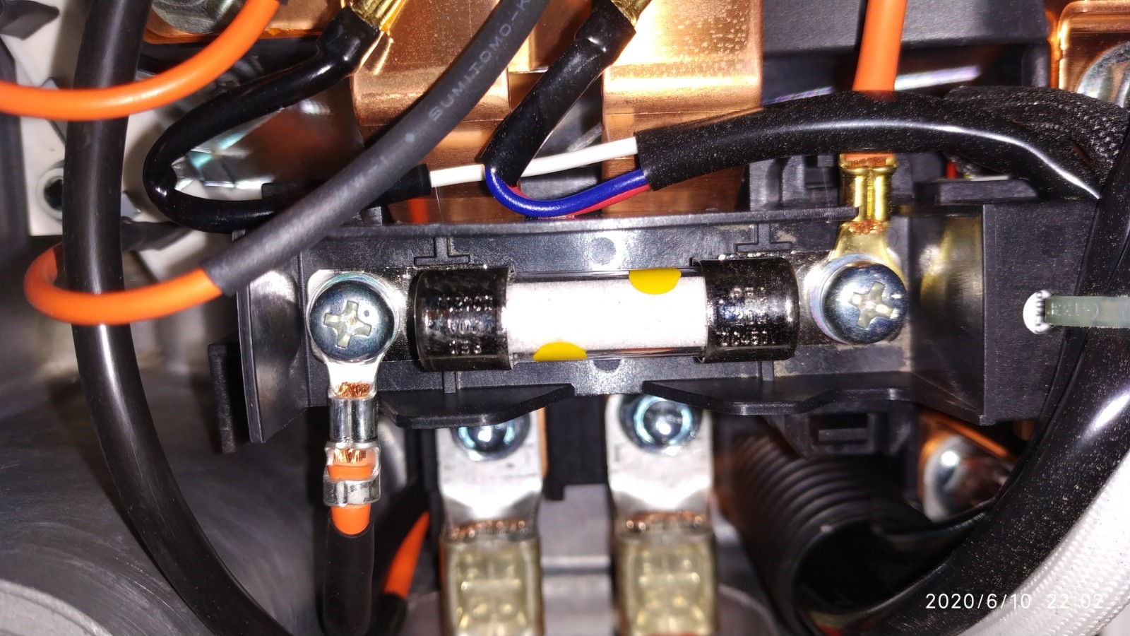
Does your car still run and drive without draining the 12V aux battery? If so then the 20A fuse in the MCU is intact and the DC/DC converter is able to chargge the aux. Usually when the snubber caps are cracked open then that fuse has blown too.
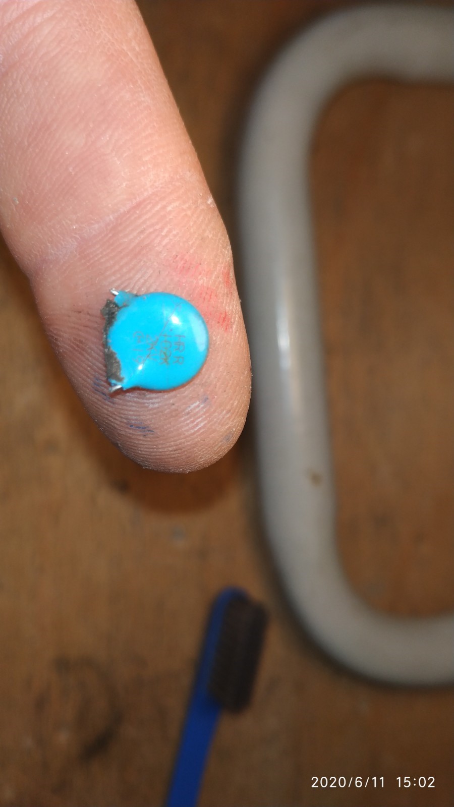
You may want to go ahead and replace those ZNR V20471U transient surge absorbers (black disc devices) while you are in there. Whatever over-voltage or surge took out that capacitor likely hit those also.
318iEV
Member
No, sadly the 20A fuse in the MCU was blown as well.
we noticed the problem because in the morning the car had stopped charging, but had only gained about 50% charge.
Thanks for the advise on those surge absorbers. I wouldn't even have considered replacing them otherwise, and since their such a cheap component its definitely worth replacing just in case.
If the 20A fuse in the MCU has blown, then the snubber caps on the bottom board will be toast. Several folks have made the snubber replacement repair "from above" which is much easier than from below. Go back a few pages and view some of the repair photos. Be careful when bending the leads not to crack the epoxy coating where it blends to the lead.
It might be a good idea to check the diodes and semiconductors before going to the trouble--if the waffle plate is damaged then it can't be repaired.
Although most folks have been able to just replace the caps and fuse and get going again.
Where are you located? The US cars have an extended warranty to cover this OBC failure.

$26.99
KISHACZ 4 PCS Car Door Lock Cover for Mitsubishi i-MiEV 2009-2020, Car Door Latch Lock Protective Cover, Door Latch Lock Cover, Door Latch Guard Car Decorative Accessories,B Black
Yuanpingshilixiuhanshangmaoyouxiangongsi

$29.99
Car Tissue Holder for Mitsubishi i-MiEV 2009-2020, Car Napkin Cover for Car PU Leather Car Visor/Backseat Organizer Hanging Paper Towel Clip Car Accessories,Orange-1
hongchuangbaihuoshangdiangerenduzi

$28.99
FIPOISA Car Rear Bumper Protector for Mitsubishi I-Miev, Carbon Fiber Trunk Door Sill Protection Strip Sticker, Trunk Door Entry Guards Plate Decorative Accessories
yuanpingshizhanghongyushangmaoyouxiangongsi

$150.00
$299.99
EP Home Smart Electric Vehicle Charger, 40 Amp Level 2 EV Charger, NEMA14-50 Wall Indoor/Outdoor Electric Car Charging Station, 240V, 25 Ft Cable
Energy Pro Cable

$15.99
Built Industrial Adjustable 3 Jaw Oil Filter Wrench with Adapter and Plier Tool Set for Auto Care
Infinite-Commerce
dutchlincoln
New member
- Joined
- Jun 21, 2018
- Messages
- 2
Hello,
I own a 2012 Peugeot Ion, and have the same issue: blown snubber caps. (thanks to this forum, i managed to detect what the fault could be).
At first, i couldnt believe that 2 of those tiny caps could be the problem, but yes; they were.
I needed to de-solder the big backplate, and couldnt really manage this with my little tin de-solder tool and my Weller iron, so i looked for someone with good experience in these kind of repairs.
I came in contact with P. Wilbrink from http://www.printplaatreparatie.nl , and discussed my problem. He was well willing to take a look at it, and we set a date for repair. In the meanwhile, i pointed him to this forum post, send him some of the schematics and findings of people here, and he ordered the parts.
Yesterday i put my electronics back into the car, and YES!! It worked again!
So, thanks to this forum and its members, i was able to repair (or better: have it repaired) my car.
I am very thankful to all of you.
I will try to share my part to this, and post some pictures of the electronics and the repair.
The backplate had some visuals of the components, so it might be helpfulin some way.
Thanks all!
And special thanks to Mr. Wilbrink!!
My regards,
Dutch.
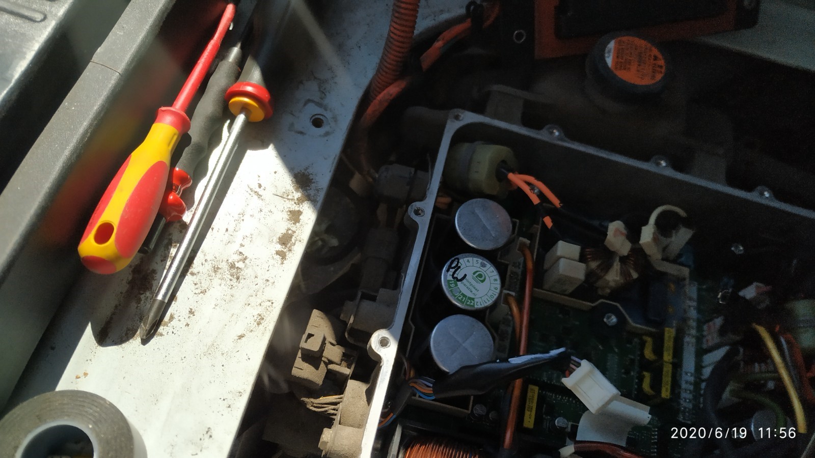
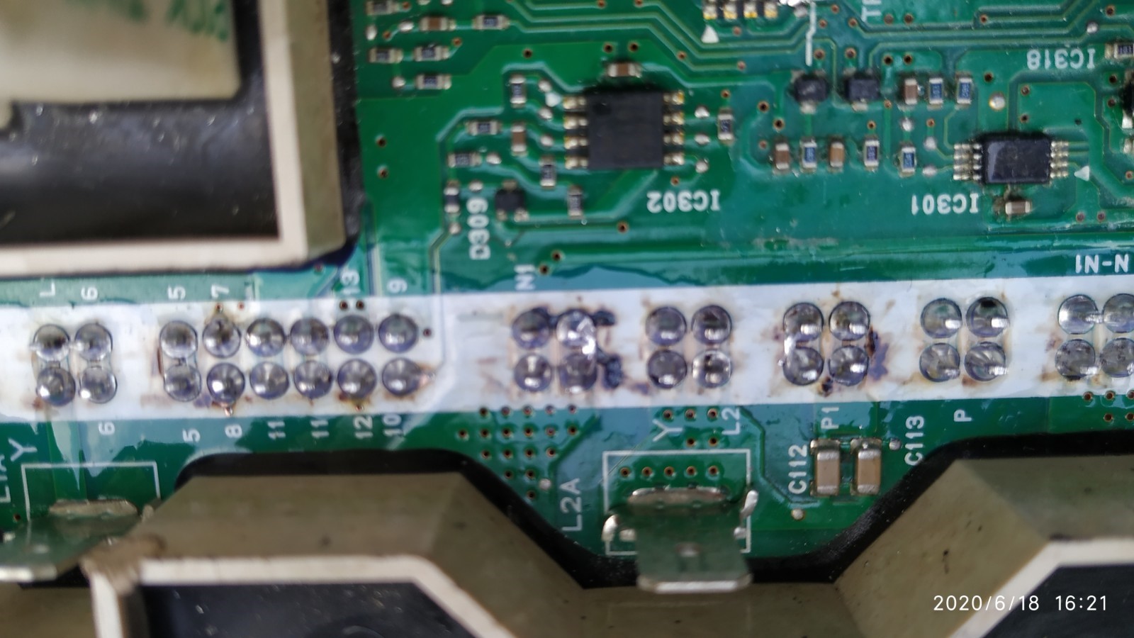
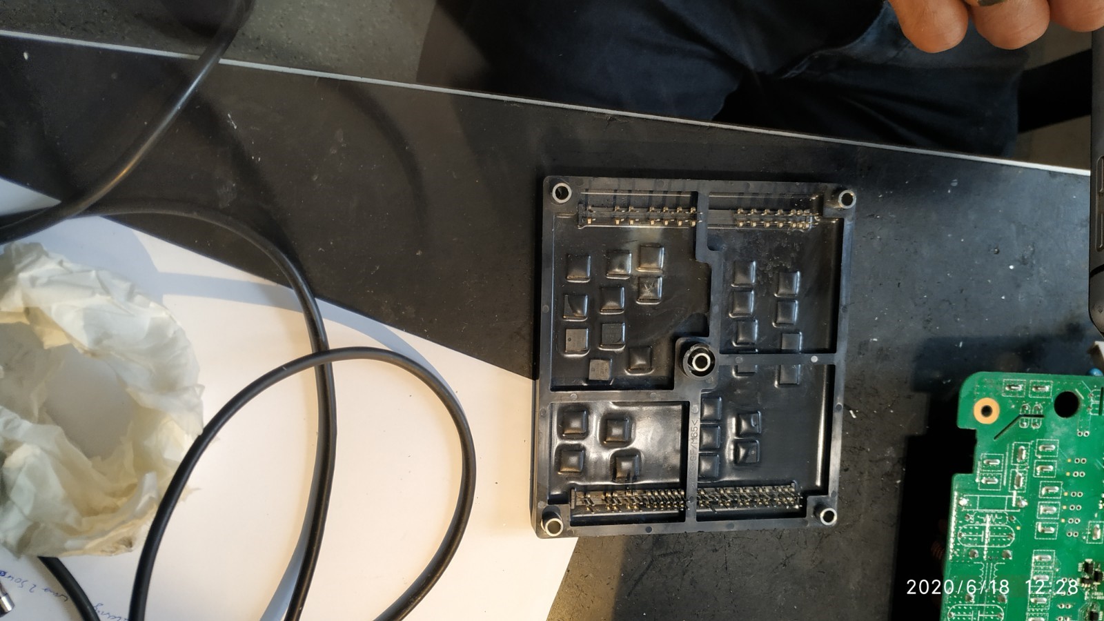
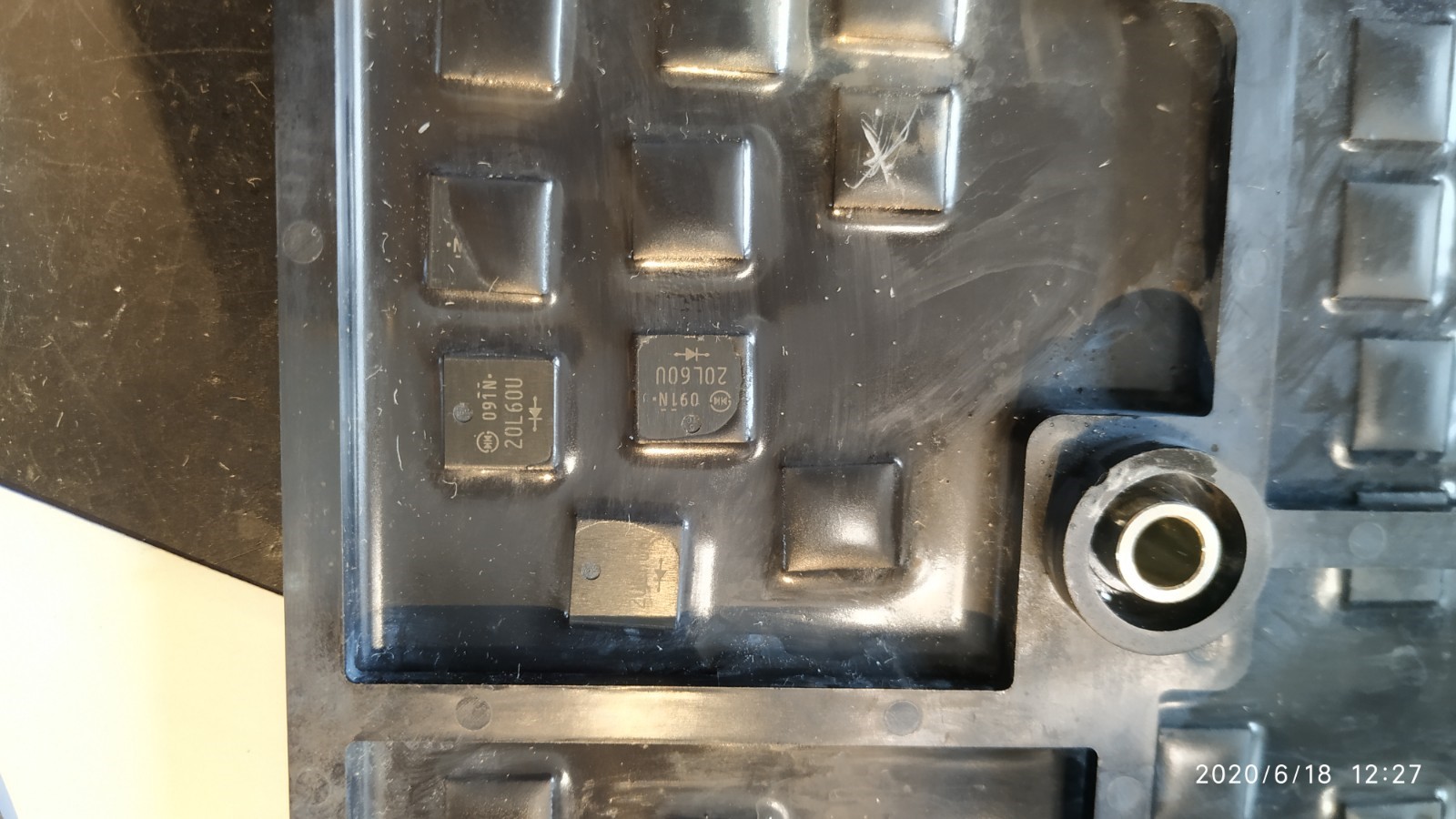
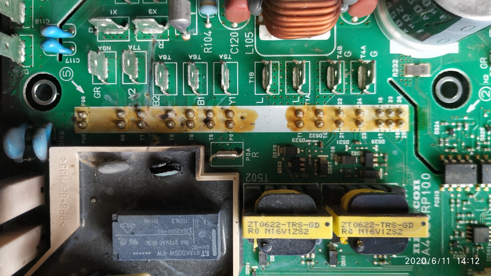
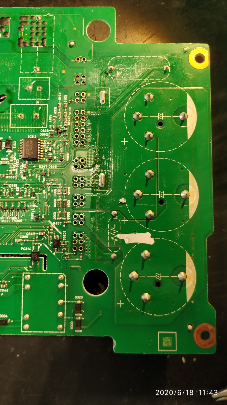
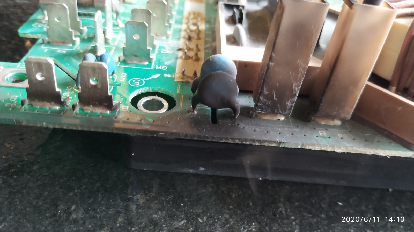
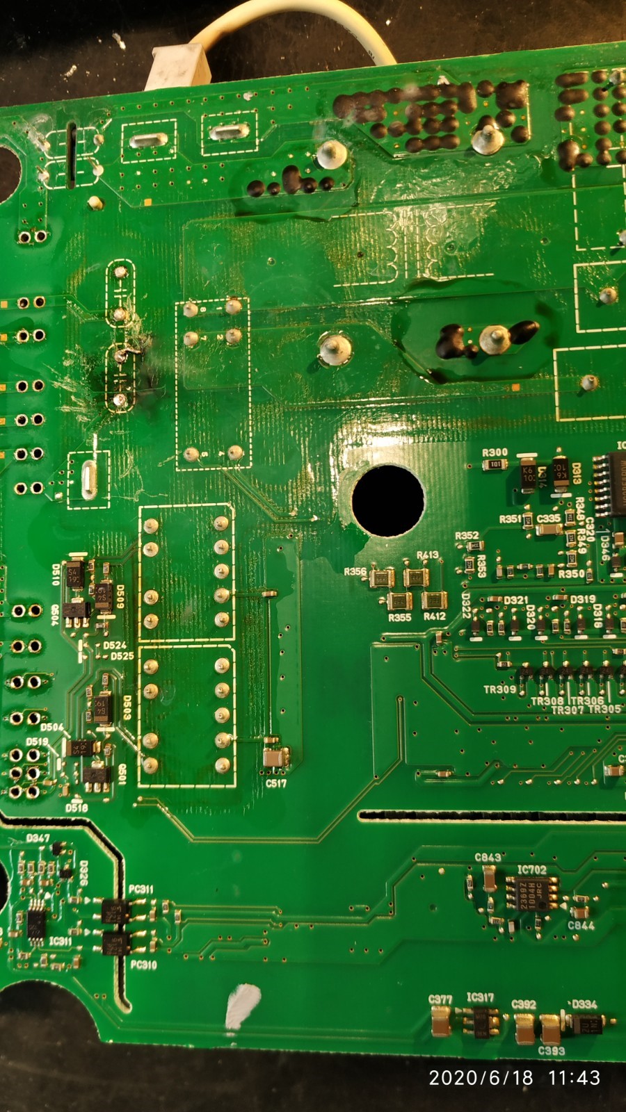
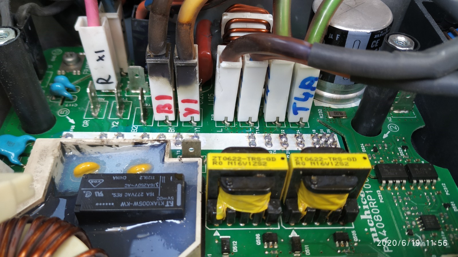
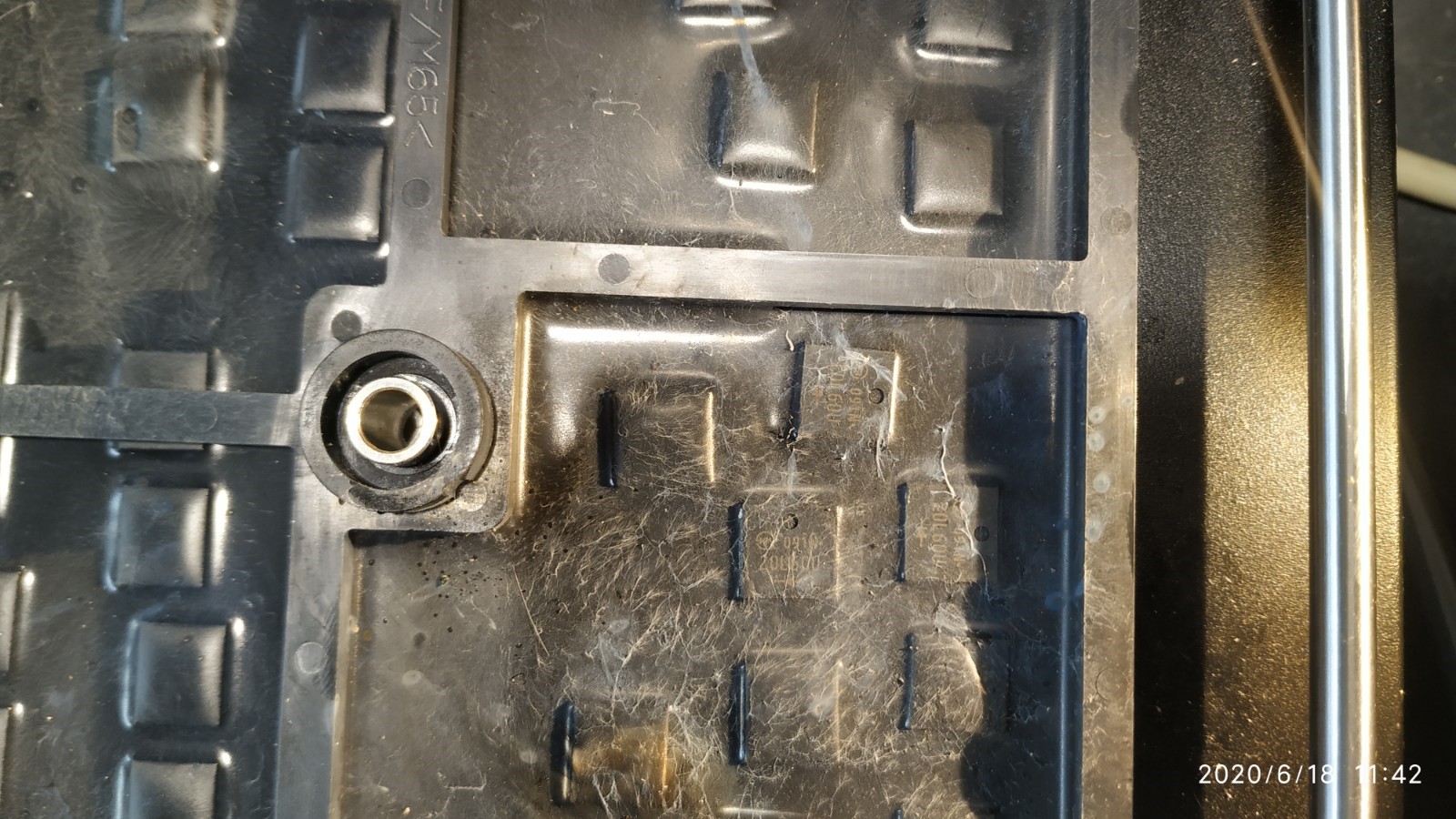
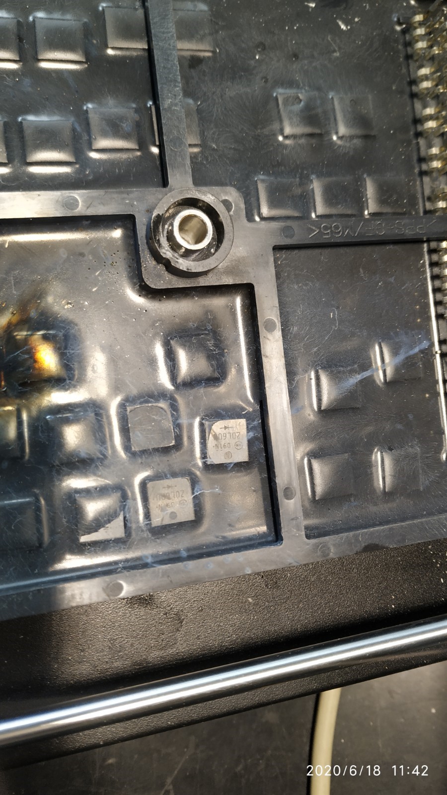
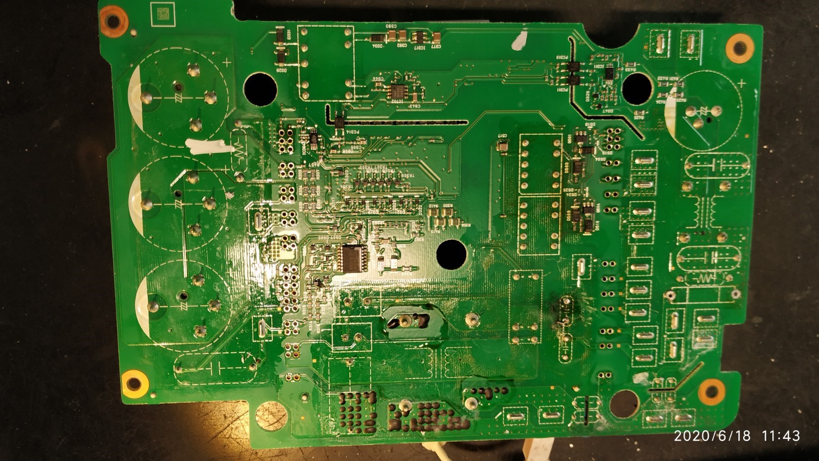
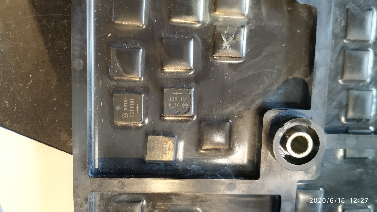
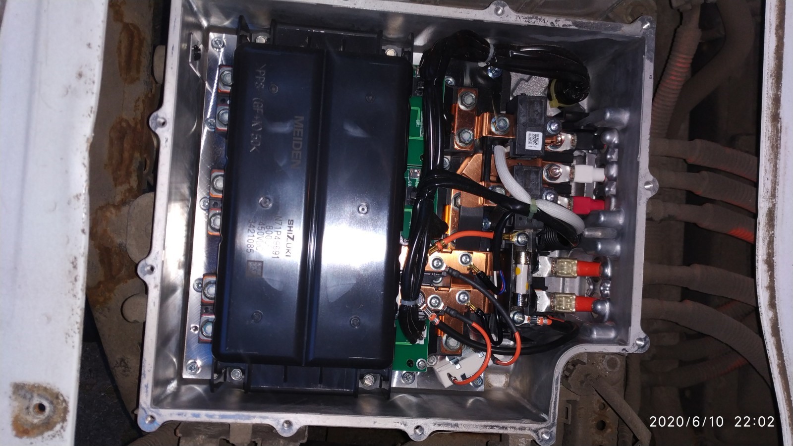
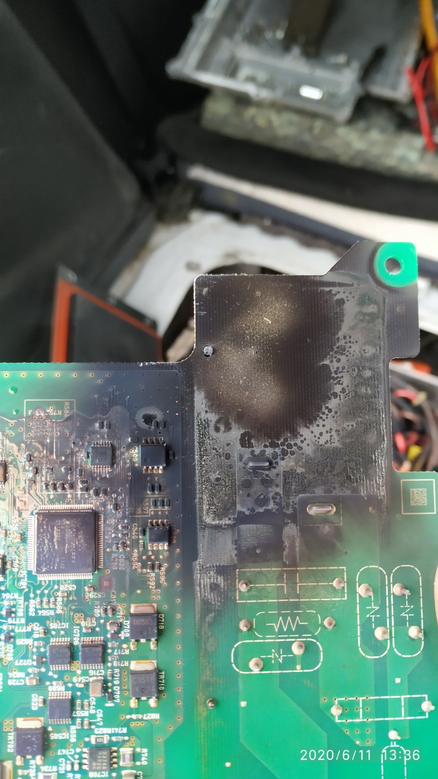
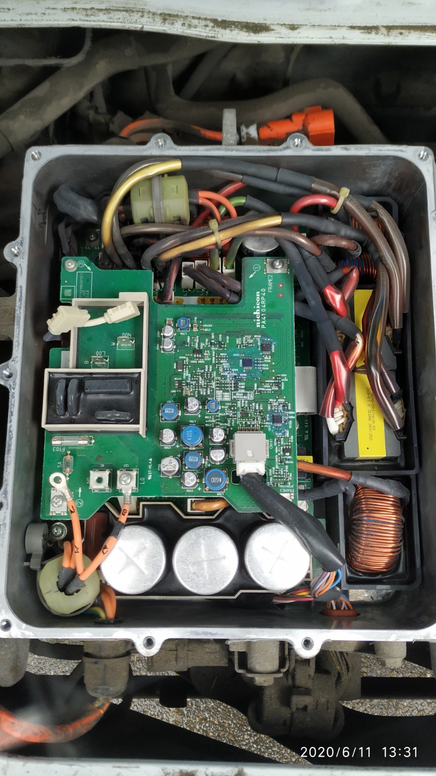
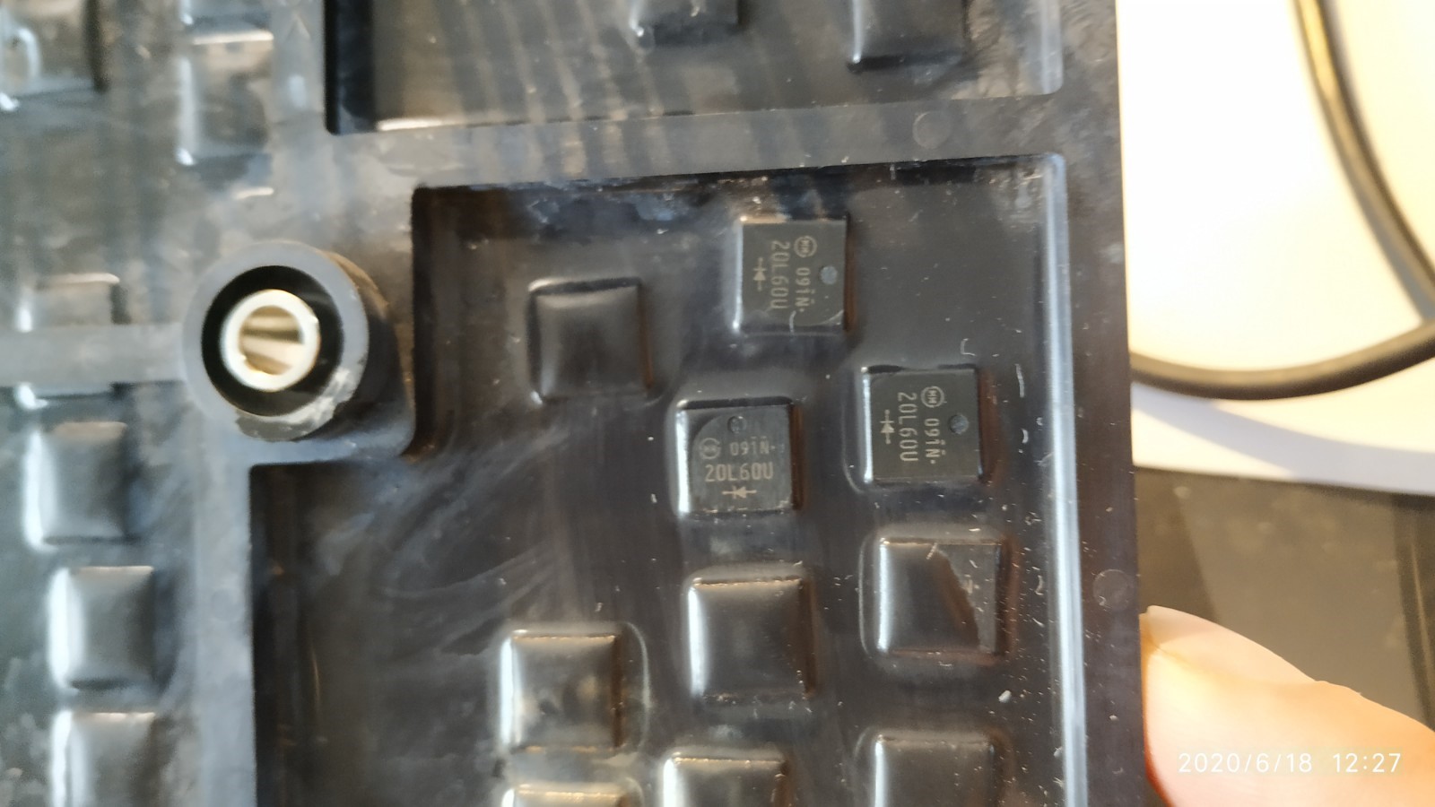
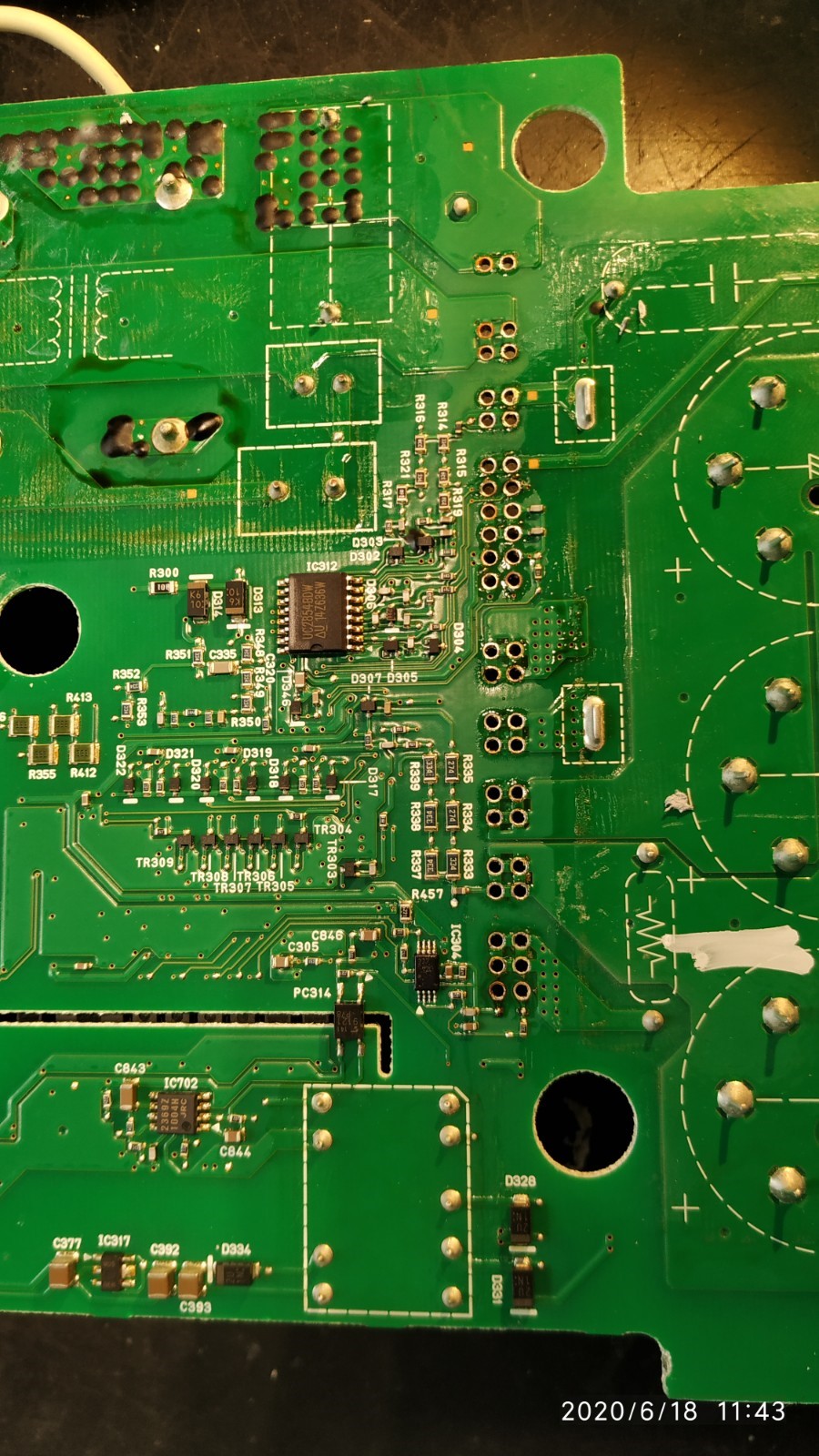


Howdy Dutch and thanks for sharing your repair experience. It's always good to hear a success story that helps keep these fun little cars running
Unfortunately i could not view the pictures as some security certificate had expired at the host site and the browser would not open them..?
Unfortunately i could not view the pictures as some security certificate had expired at the host site and the browser would not open them..?
coulomb
Well-known member
Those images didn't display for me, due to what seems like a https problem (maybe expired certificate).
[ Edit: I see that once I forced the certificate on one, they all displayed. Or maybe it was because I viewed and saved them all; anyway, I hope it saves some readers a lot of trouble. ]
[ Edit 2: Oops! I only got every second one. Done now. ]
[ Edit 3: Sorted into date order. ]
I took the liberty of extracting them and posting them here via imgur.com .
20
03
22
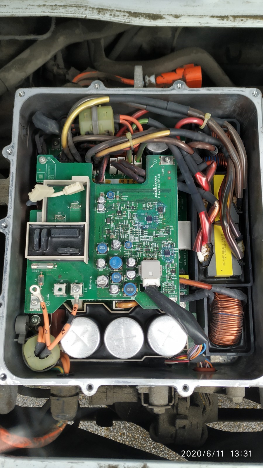
21
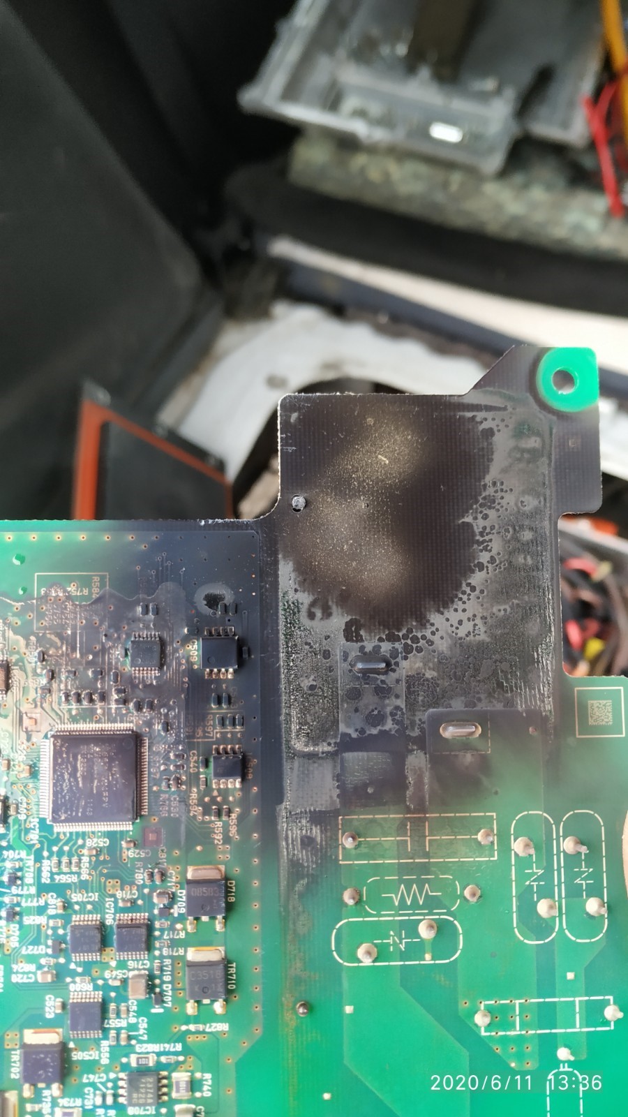
Woe! That must have been a hell of a repair job.
13
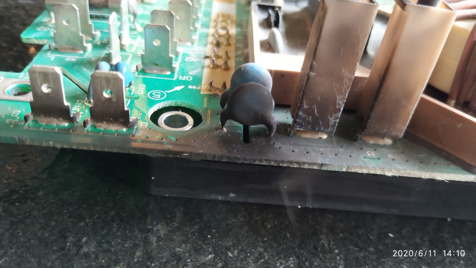
11
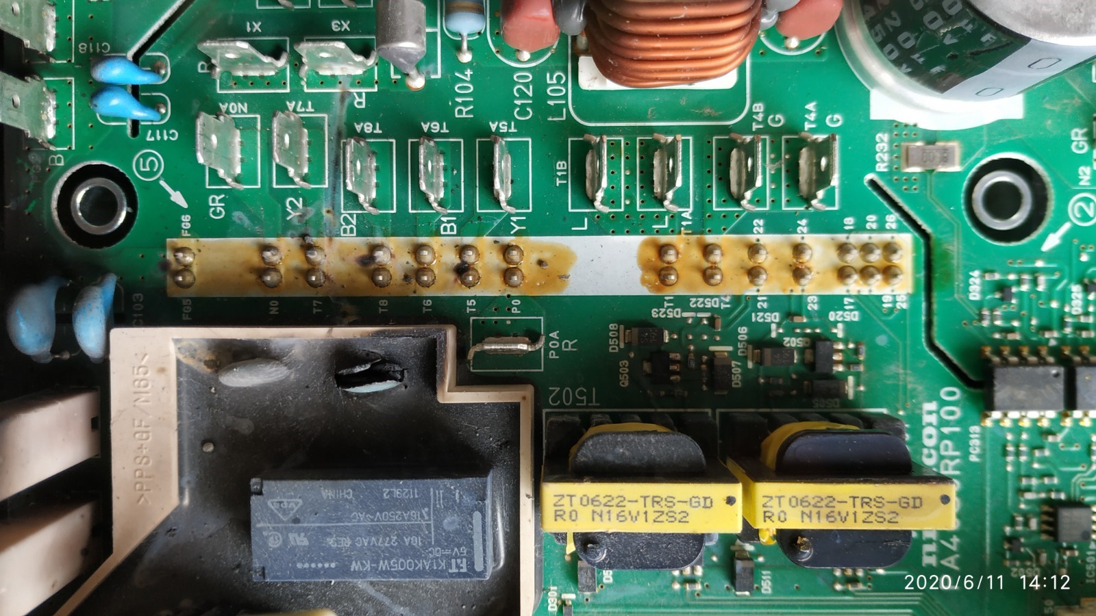
04
02
06
16
17
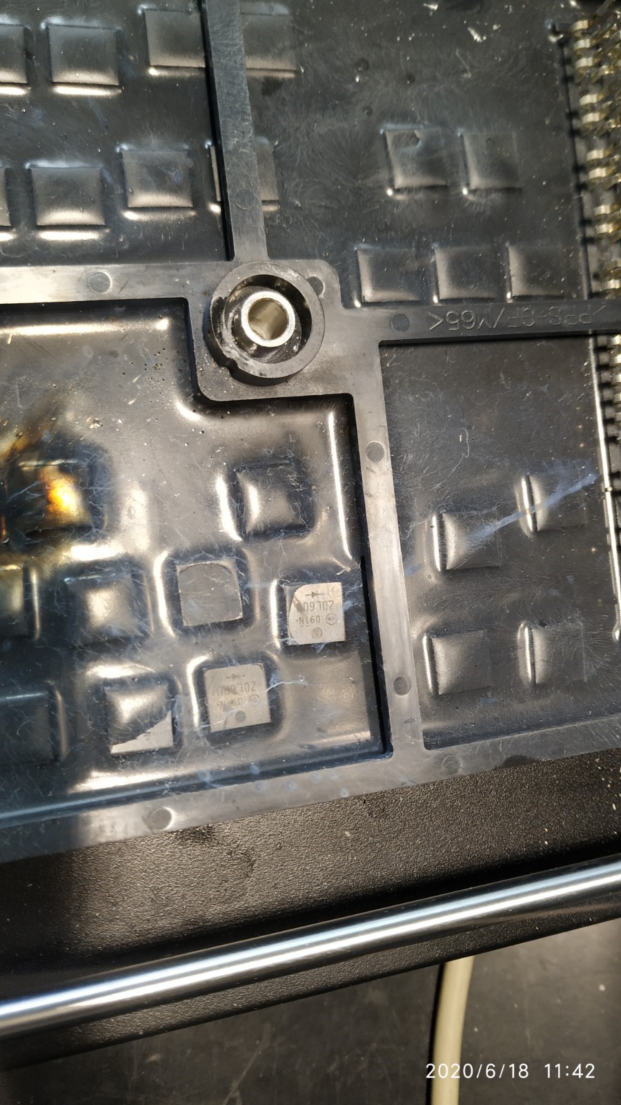
07
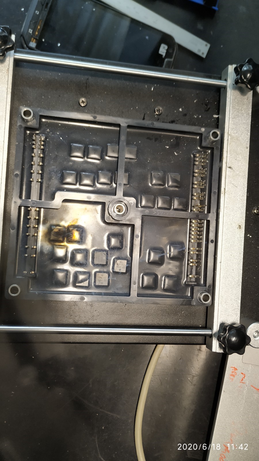
18
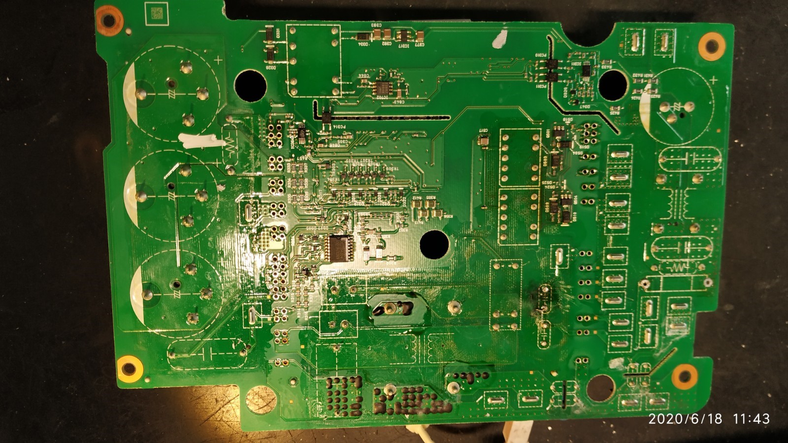
14
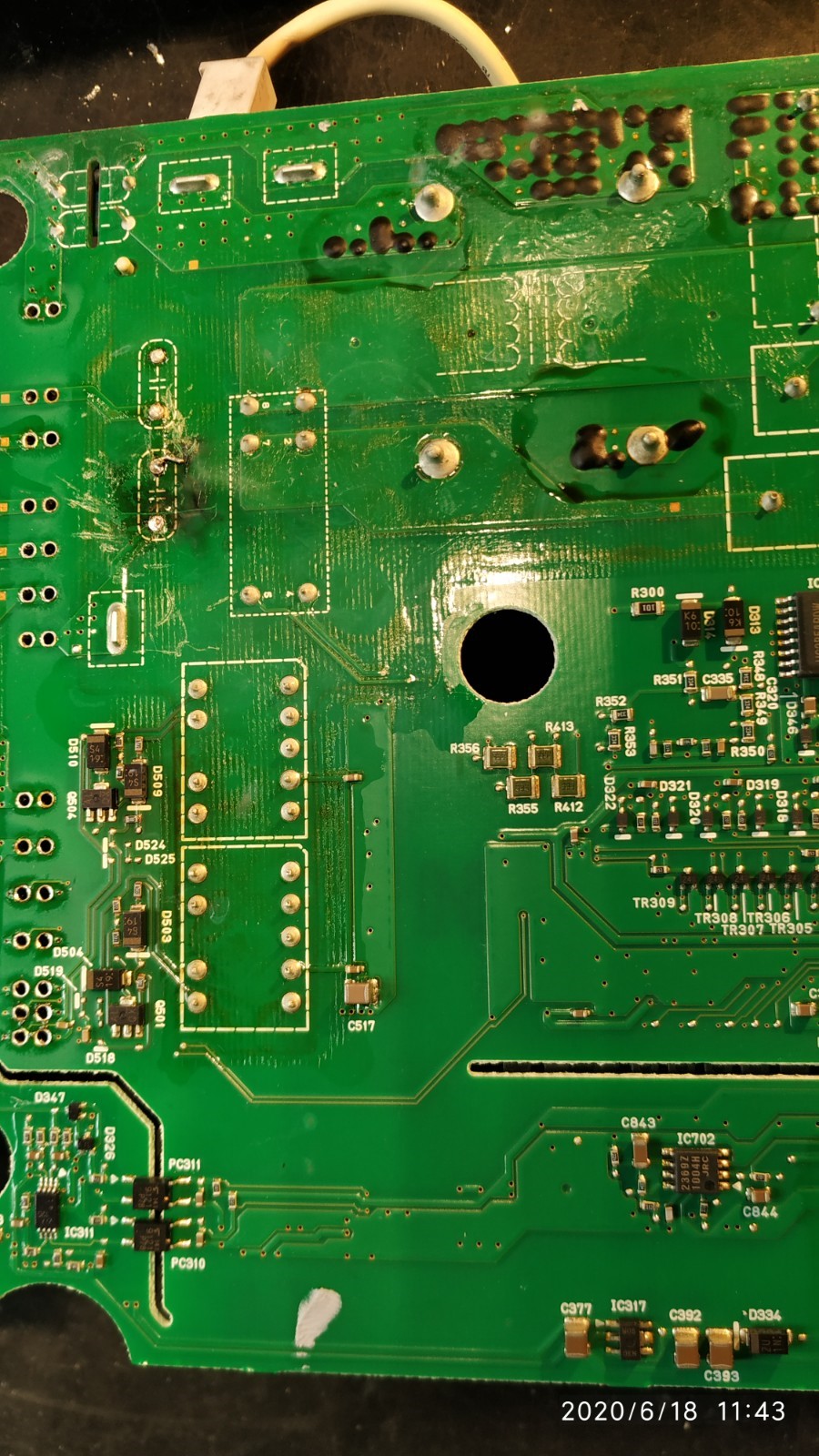
24
12
25
09
10
23
19
08
01
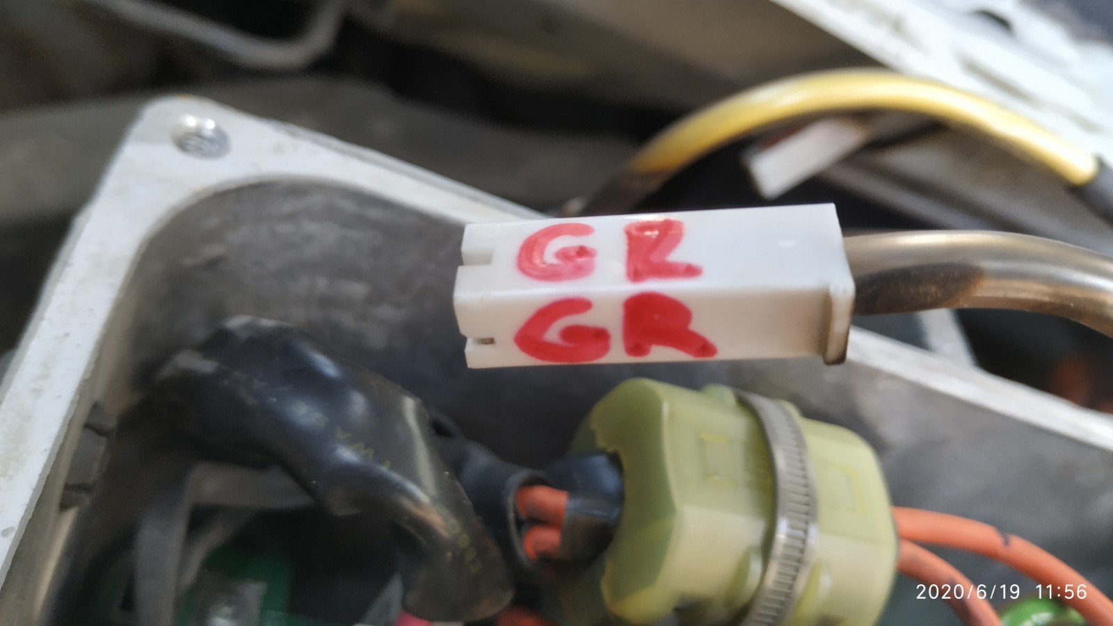
15
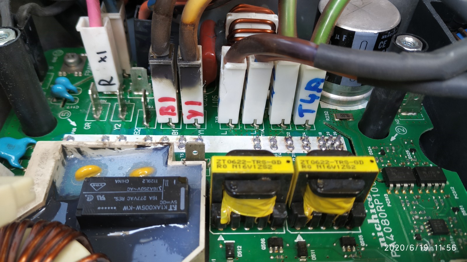
05
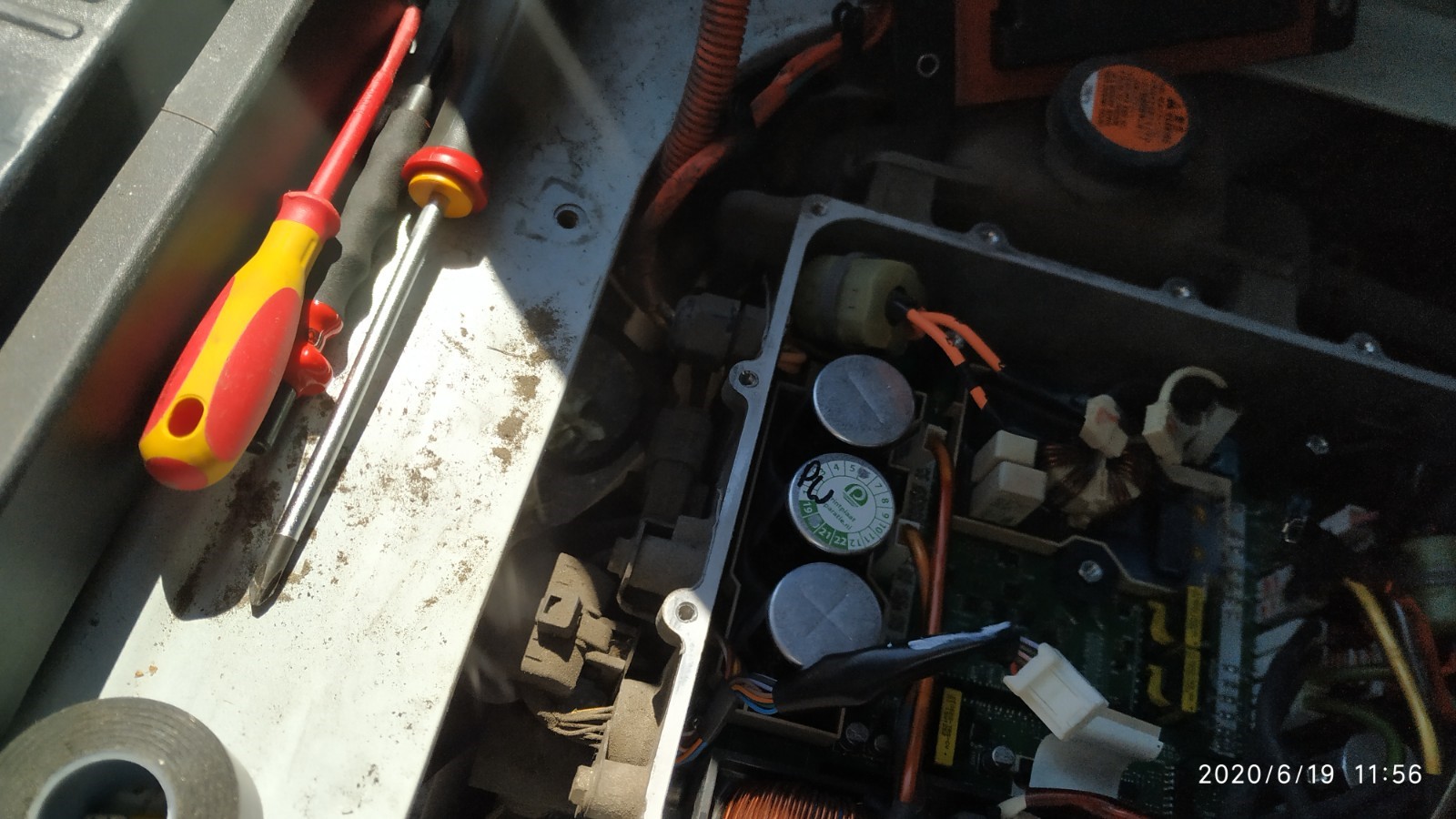
26
[ Edit: I see that once I forced the certificate on one, they all displayed. Or maybe it was because I viewed and saved them all; anyway, I hope it saves some readers a lot of trouble. ]
[ Edit 2: Oops! I only got every second one. Done now. ]
[ Edit 3: Sorted into date order. ]
I took the liberty of extracting them and posting them here via imgur.com .
20

03

22

21

Woe! That must have been a hell of a repair job.
13

11

04

02

06

16

17

07

18

14

24

12

25

09

10

23

19

08

01

15

05

26

coulomb
Well-known member
I added the odd numbered images in the above post, for those that might have missed my edit.
[ Edit: and re-ordered in order of date and time. ]
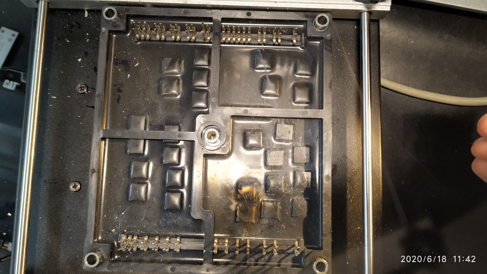
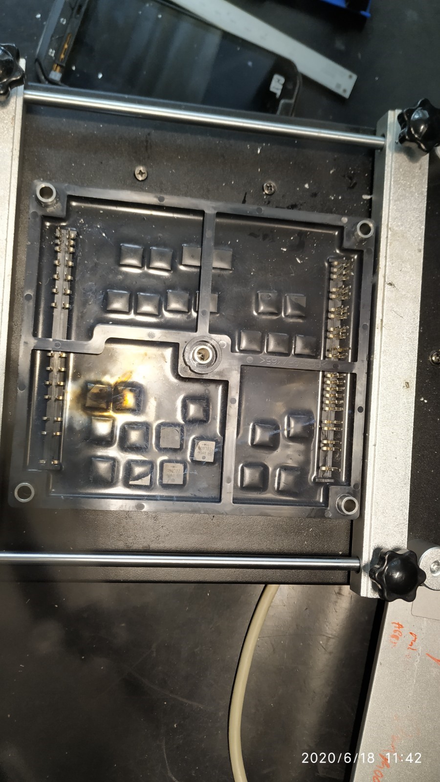
Do you know if Mr. Wilbrink had to replace the parts on the Waffle Plate™ that appear to be burned? Or did they just get really hot and yet survived?
[ Edit: I now see that the yellow sheen/muck must be from the capacitors as well. In later photos, we see it cleaned up nicely. ]
Any idea how he got the potting mix off the parts? Did it just chisel off? [ Edit: now I see it seems they didn't use quite enough potting mix to cover all the devices. ]
I'm quite surprised about the burned corner of the top PCB. It seems absolutely fine from above... or was that board replaced? Also, I can't see what would have gotten so hot that it burned the bottom of the board like that. Parts for centimetres about received a really bad dose of soot! I hope he managed to clean that off; it can cause weird problems if left on. Or maybe the board has really, really good conformal coating.
[ Edit: It's just occurred to me that the soot must have come from something below that board. Any idea what it was? Ah. The two small capacitors? ]
Anyway, congratulations on a miraculous repair! And well documented with photos!
coulomb
Well-known member
I guess there is a lesson to be learned from this repair. If you choose to replace the capacitors without removing the lower board from the Waffle Plate™, you risk leaving some soot on the top of the Waffle Plate™. I'd say the devices themselves would be fine; that potting mix and the epoxy of the devices should prevent any problems of flash-over to other parts or to the presumed PCB below.
But some soot might end up near the pins from the Waffle Plate™ to the lower board. It would be worth attempting to clean that area as best you can around the pins where they exit the Waffle Plate™.
You may also have to clean the bottom of the top board, but that should be easy, and not removing the lower board has no impact on that. I imagine that most of the soot goes up not down, so if the top board is pretty clean, then the Waffle Plate™ pins are likely to be even cleaner.
318iEV
Member
I’m located in NZ, plus this iMiEV was imported from Japan so sadly nothing’s under warranty.
Luckily there are no soot/burn marks anywhere in the OBC apart from right next to the failed snubber, and after peeping between the gaps the waffle plate doesn’t show any visible signs of failure.
I have replaced the two snubbers with 3kv ones and am currently waiting for the replacement LE105 cap, transient surge absorbers and 20A fuse.
From what I’ve seen there is also a relay that can fail too though I’m not too sure where on the board to test it from, any help would be appreciated.
Thanks
@ coulomb, Thanks for hosting those pictures.
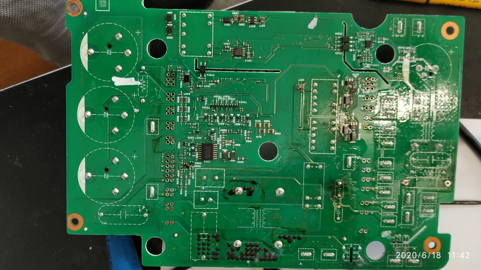
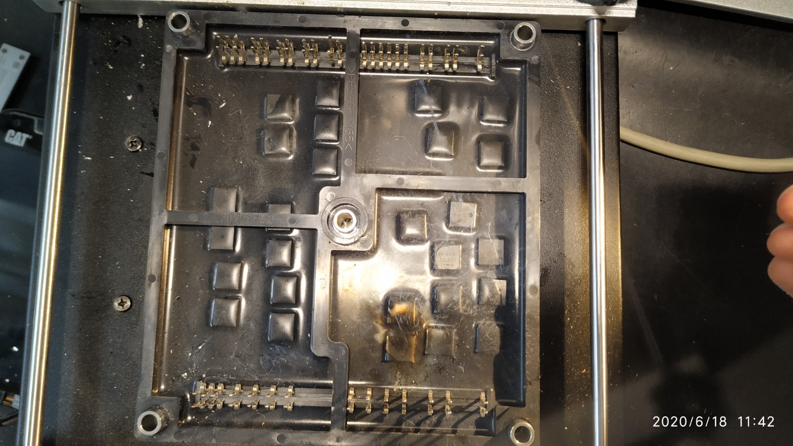
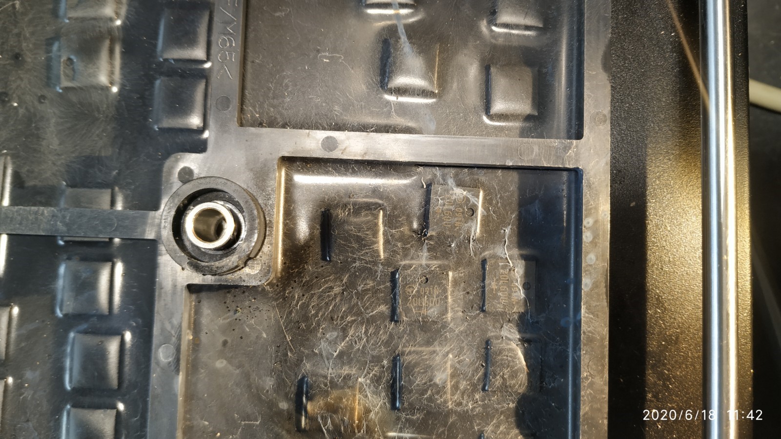
All that soot and molten metal [pic# 21]looks to me that the OBC was operating with a split snubber [pic# 11] that was arcing and eroding over some length of time. Look at the size of that gap! That looks like arc erosion has just eaten out the dielectric material and spread it inside the box. [edit, couldn't think of the word in the early morning]
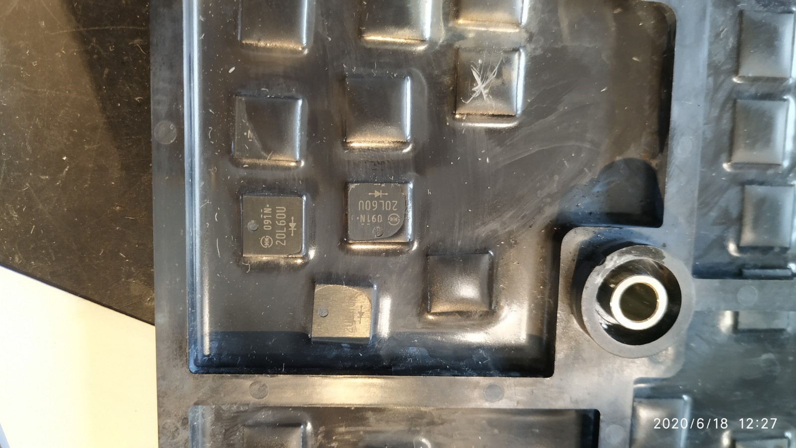
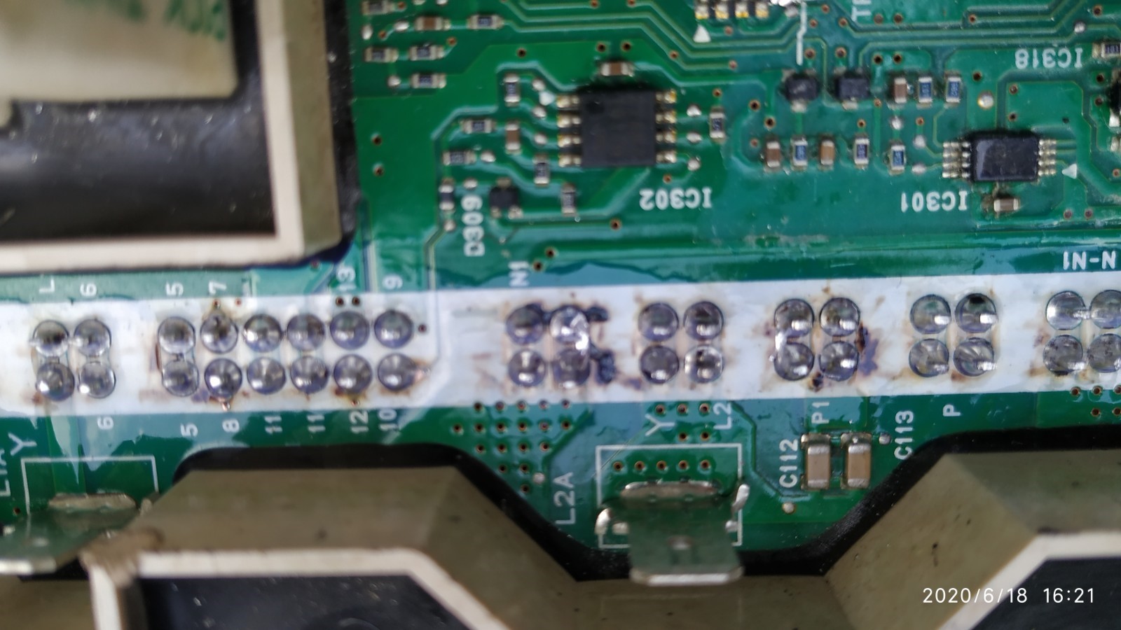
There appears to have been burn marks [pic# 08] around some of the solder joint thru holes? don't know if that is from arcing or solder removal.
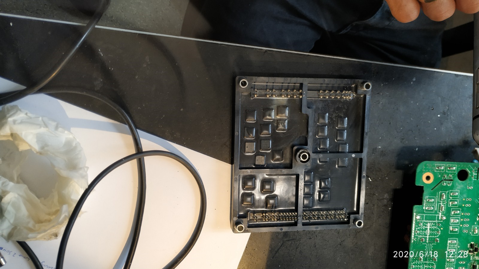
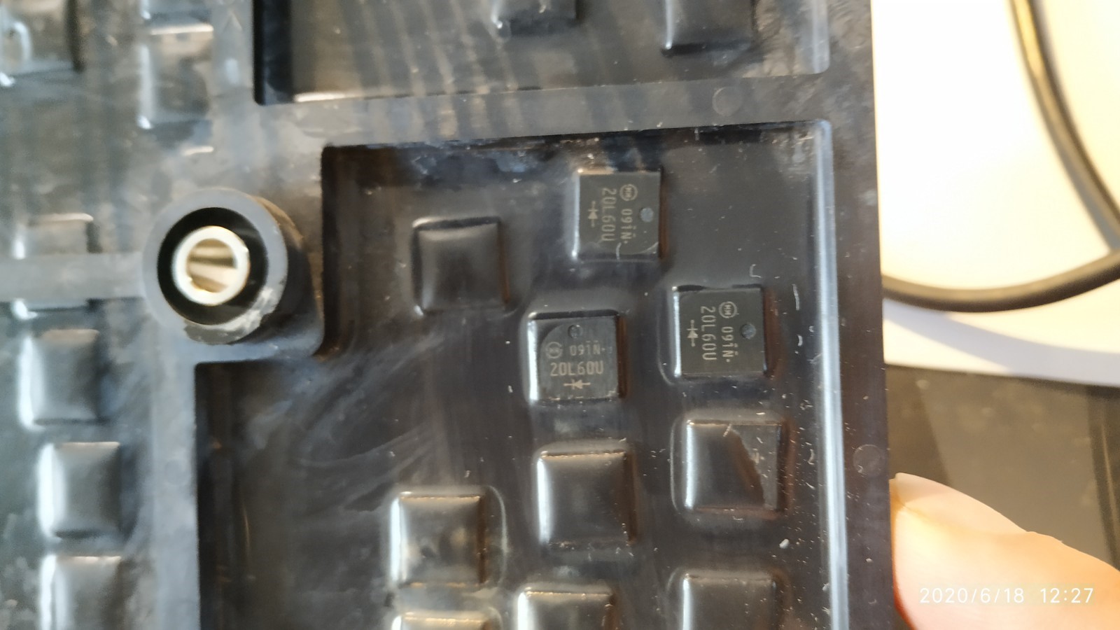
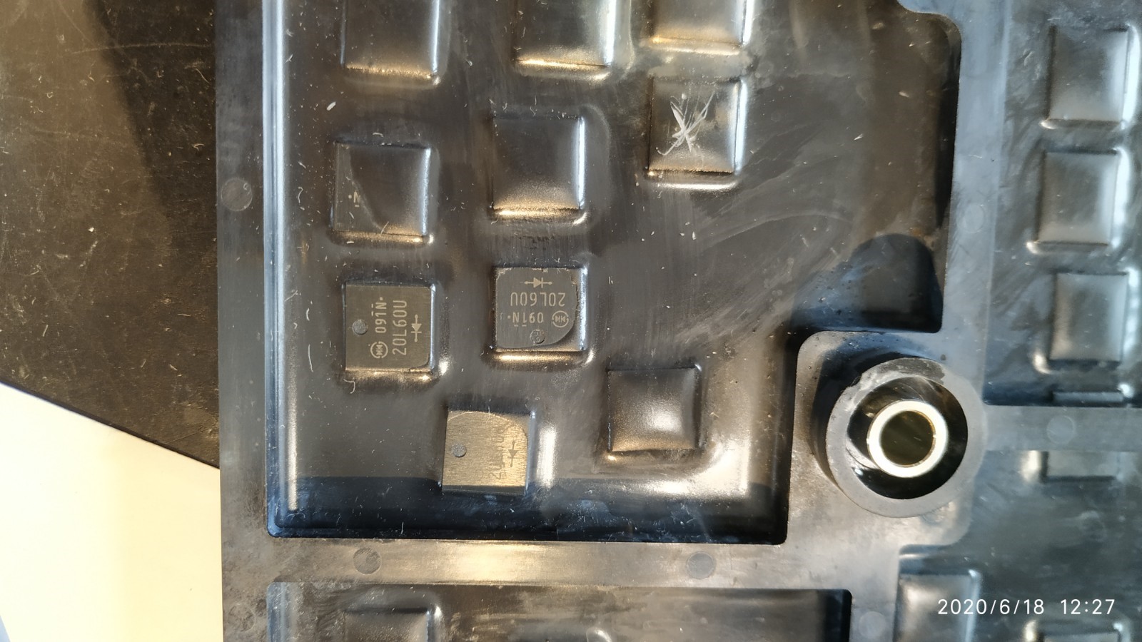
And the metal spheres and soot on the waffle plate looks like there may have been arcing between the un-cut or extra-long leads at the solder joint of the snubber cap [pic# 25]. i'm assuming they just cleaned the waffle plate and didn't replace anything in it. It's amazing that some FET or diode wasn't damaged in the plate.
The strangest picture is lucky [# 13] where it is showing soot on the backside of the AC line input covers and the decoupling capacitor at the card edge. It also shows a side view of the snubber to see the huge gap between the electrodes.
The story of these pictures appears to me that the OBC was still operating in a degraded condition with a broken snubber up until some time later when the MCU fuse broke.
Most other failure pictures have shown a snubber that is just cracked open a bit with a small amount of residue; these would be failed snubbers due the MCU fuse breaking first.
@318 , for testing the AC input relay.
Here is a link with a good picture of D301 which is a good point to apply 4.5V with a 200mA current limited power supply. i wouldn't connect a battery without current limiting and do be careful of the polarity.
http://myimiev.com/forum/viewtopic.php?f=23&t=4079&p=37548&hilit=relay#p37548
You can measure the resistance between the White Faston tab and the "Neutral" on the waffle plate solder joints as you activate the relay: ~10R when Open and shorted when Closed.
http://myimiev.com/forum/viewtopic.php?f=23&t=4079&start=30#p36735
coulomb
Well-known member
I agree, and was thinking similar thoughts, but not in as much detail.kiev said:All that soot and molten metal [pic# 21]looks to me that the OBC was operating with a split snubber [pic# 11] that was arcing and eroding over some length of time.
Look at the size of that gap! That looks like arc erosion has just eaten out the guts and spread it inside the box.
Perhaps one capacitor failed first, and unusually failed not shorted but medium impedance. Operating at pack voltage, it would get hot. Amazingly, it stayed that way, eventually boiling its contents and depositing it on the PCB above and on surrounding components. The medium impedance was not enough to blow the MCU fuse.
I find it harder to explain the soot or more likely metal deposited on the waffle plate. Perhaps as you suggest @Kiev, there was arcing under the board as a result of extra long pigtails. Maybe arcing under the board happened first, heating the capacitor above and tipping it towards failure.
Finally, the second capacitor failed, and as is far more common, it failed shorted, blowing the MCU fuse and alerting the owner that there was a problem. Perhaps it was affected by the same heat that fried the first one, but failed later as it was further away from the source of the heat (either the arcing below the board, the first capacitor failing medium impedance, or both).
> And the metal spheres and soot on the waffle plate looks like there may have been arcing between the un-cut or extra-long leads at the solder joint of the snubber cap [pic# 25].
Well spotted, I didn't notice the metal spheres. It seems unlikely to me that extra long pigtails would be present from the factory; it depends on how they buy the capacitors. So this might have resulted from a botched repair job. Possibly performed from above, so there was no opportunity to do the obvious tidying up, including clipping the pigtails. The metal spheres might even be solder, resulting from inserting and soldering from above.
BTW, the numbering of the pictures was just my way of keeping track of them when reordering them. The numbers are actually in front of the img tags, so refer to the image to the right or below. But no matter, I'm glad that they served another purpose.
Edit: the numbers indicate the order of the original images. Pity it's now such a pain to find a particular image (use search I guess).
zetafunction
Active member
- Joined
- Jul 31, 2020
- Messages
- 35
Hello,
I own a 2011 Citroën C-Zero which does not charge anymore at 220VAC. Fast charging does work. When I connect the 220V charger, it tries to charge and after 5 seconds it stops. The OBC Error codes are 39 and 42.
I opened the OBC unit up and took out both boards, everything looks fine. I double checked under the microscope and could not see anything wrong. However I did not desolder the backplate of the second board yet.
Can you please give me any advise on what to check first? Thank you very much!
Howdy zeta,
If you can somehow share the pictures then we can look to see if there is something abnormal.
Your OBC codes indicate 2 different problems on opposite sides of the board.
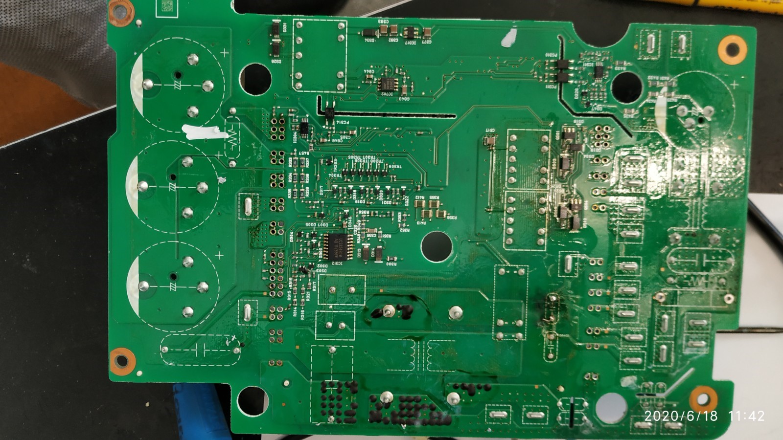
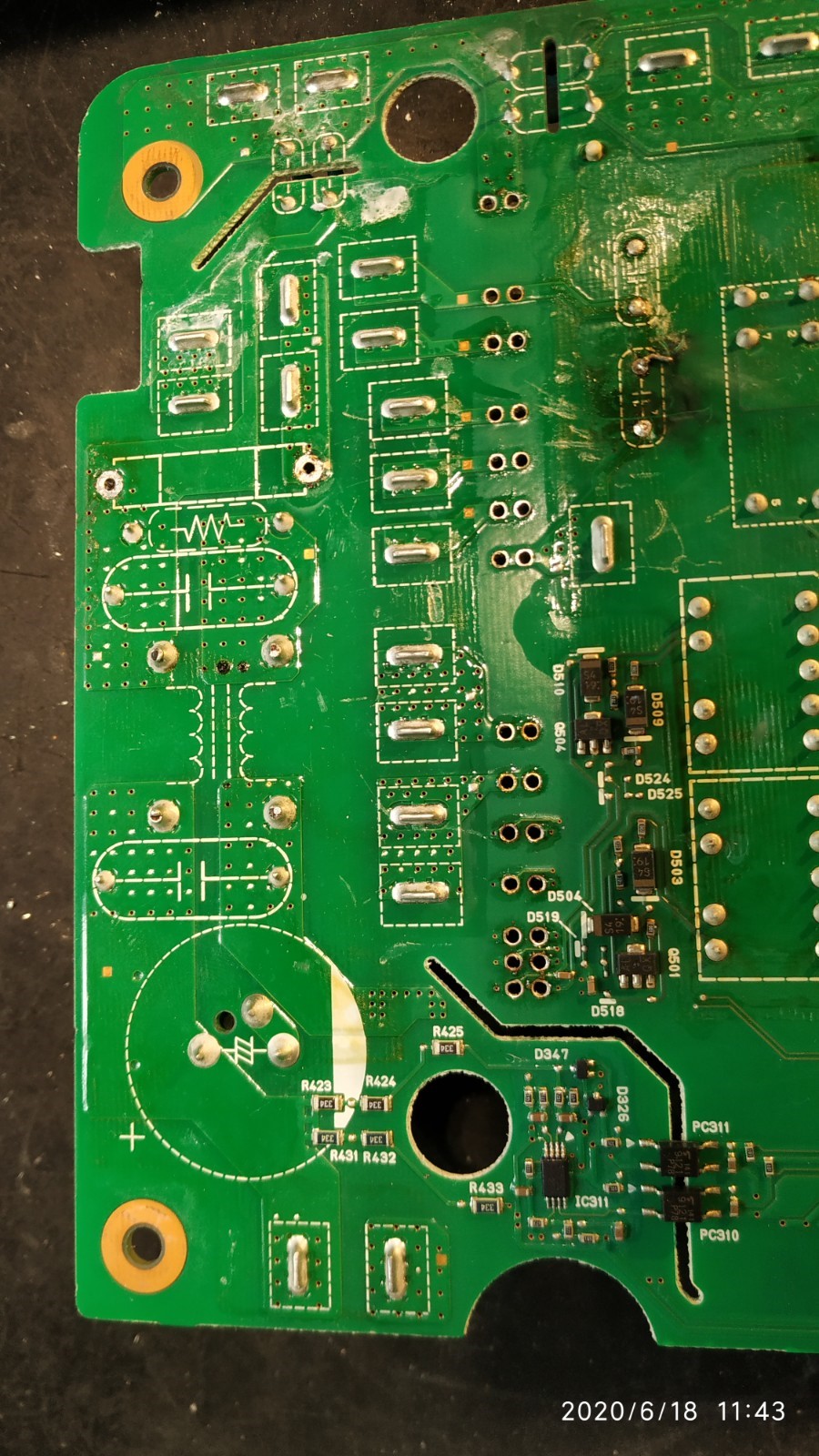
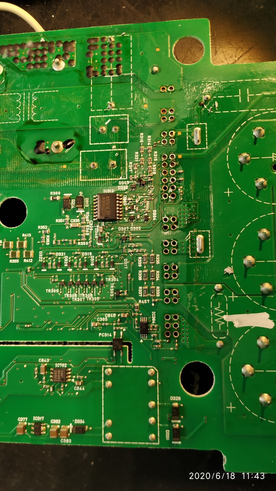
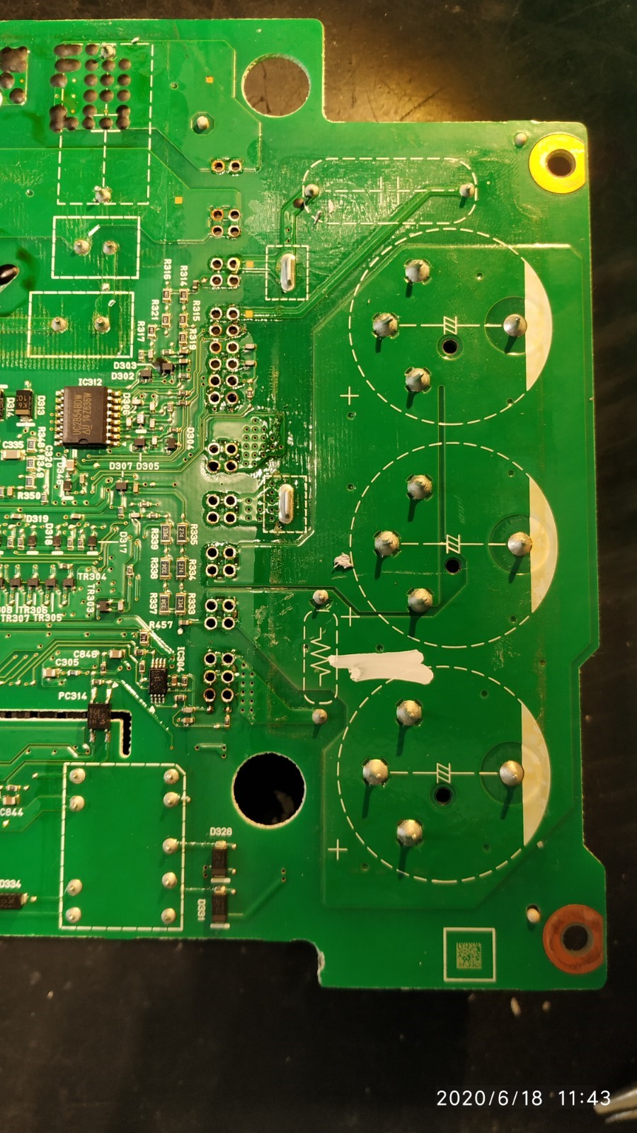
OBC 39 is Power factor correction (PFC) circuit output voltage abnormal; the PFC boost is done after the rectification of the input AC voltage and is in the vicinity of the 3 large capacitors on the bottom board. The control ic IC312 for the PFC is on the bottom side of the board, so i would recommend to check all the diode drops in the waffle plate first to rule out a major semiconductor failure.
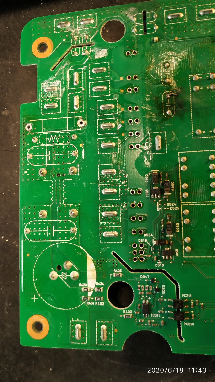
OBC 42 is Output current sensor zero-point abnormal; this is telling me that there is a bias voltage or bad feedback in an op amp circuit. The output should be zero when no current is flowing on the output, but it is reading some voltage that is interpreted as a current in the sensing circuit. This is located in the vicinity of the single large capacitor, resistor R232, and a high voltage isolation slot cut out in the bottom board.
The one thing in common is that both of these signals are sent to the top board for reading by the main controller chip, and they may share the same low voltage power supply. Which means the issue could be on the top board digital section. So closely inspect both sides of the top board looking for scorch marks or puffy capacitors.
zetafunction
Active member
- Joined
- Jul 31, 2020
- Messages
- 35
Thank you for your fast answer!
You can find all the pictures of the boards here: https://imgur.com/a/zUoyObd
I just checked the board again and I can not spot anything burn marks or damaged parts. Then I checked all of the diodes I could reach with the diode setting of my multimeter. Diode D301 has a drop of 0.0925V on both sides, is this normal?
D301 is the freewheeling diode for the coil on the AC input relay inside the potted region. It should read about 60 Ohms and will cause the diode drop to read like you did.
F701 is a fuse on the top board, likely okay but doesn't hurt to check.
The diodes i am worried about are inside the waffle plate with the big heatsink soldered to the bottom board. There is a diagram with the voltage drops that you can measure on the solder joints on page 45, but there are some good pictures of the plate and underneath the board on the previous page of this thread.
latest schematic of waffle plate is here:
https://drive.google.com/file/d/1tHilCxdM7tmisq-a1U_R6NnYbFyOVV85/view
zetafunction
Active member
- Joined
- Jul 31, 2020
- Messages
- 35
I just checked all diodes with your great schematic and they seem to be fine. I also checked F701.
What should I consider doing next?
What should I consider doing next?
Similar threads
- Replies
- 5
- Views
- 617
- Replies
- 21
- Views
- 2K
- Replies
- 0
- Views
- 723
- Replies
- 6
- Views
- 8K
- Replies
- 5
- Views
- 2K


