DBMandrake
Well-known member
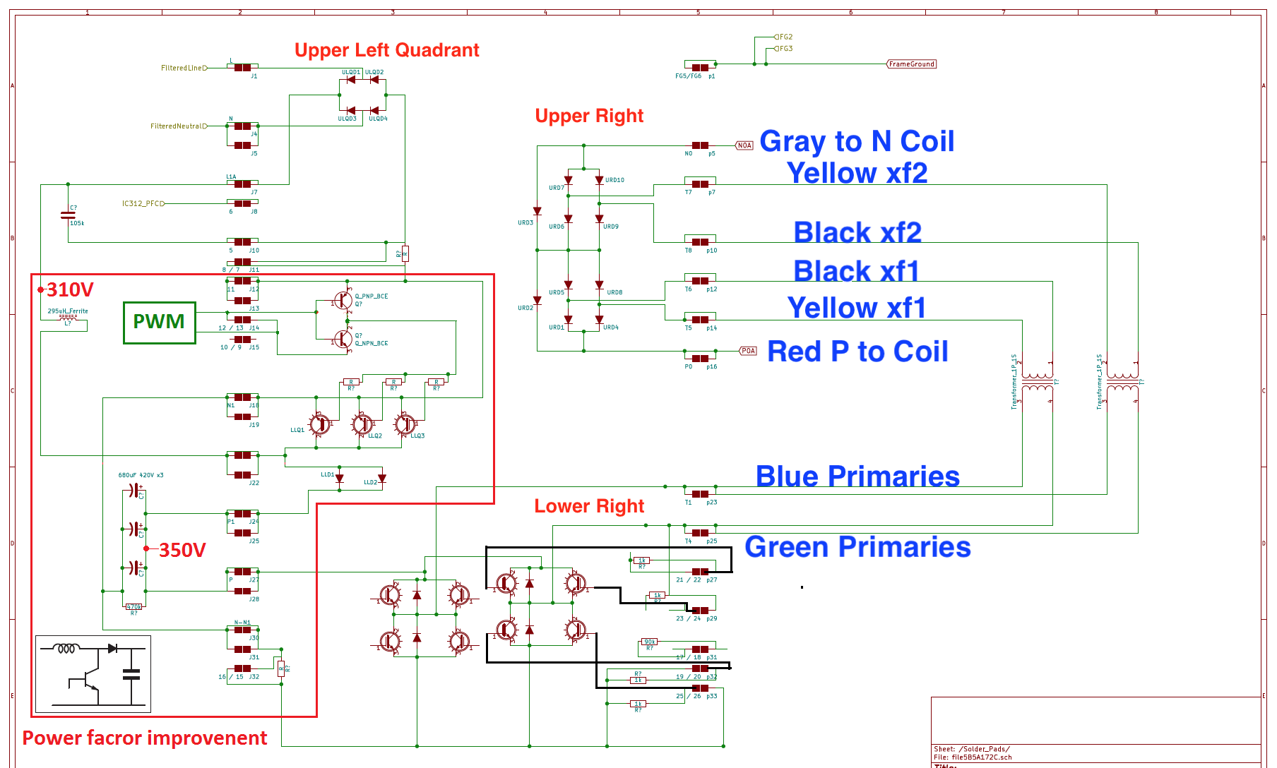
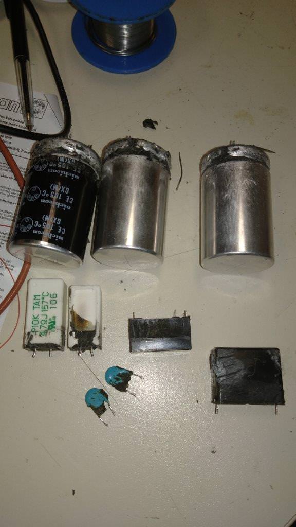
The snubber caps in my OBC were definitely 2kV not 3kV as shown in your diagram - one was undamaged and easy to read. I fitted 6kV replacements which were approximately 3x as thick as the original discs.kiev said:Here is a simplified functional schematic of the OBC, MCU and Pack, showing details of the HV DC Output section with the snubber caps and MCU fuse that seems to blow.
The DC/DC converter can draw more than 10 amps though when the car is being driven I presume ? Otherwise why make the fuses more than double the current drawn - which actually peaks at less than 9 amps while charging.During charging there is about 10 Amps of current from the OBC to the Pack thru the MCU 20A fuse.
Ok that's new to me - are you referring to the fuse on the corner of the main PCB not far from the snubber caps ? I thought that fuse was on the input side of the charger ? If it's directly in series with the other fuse why bother to have both ?The 20A fuse in the OBC has never been found to blow even though it is in the same current path as the MCU fuse?

Anyway as to why doesn't it blow instead - it's not that surprising. While they're both nominally 20 amps they're significantly different in design and will have different fusing speeds. If the triggering event is a snubber going shorted (which is still what I favour) then whichever fuse is a faster fusing type is going to blow first and save the other one... it's possible of course that the other fuse has now been "stressed" and could potentially fail in the future.
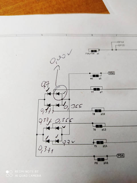
BTW the snubber caps are not connected to the output of a regular 4 diode bridge as shown as far as I remember - they're connected to the maximum output branch of that large conglomeration of diodes on the waffle plate shown on one of your earlier hand drawn diagrams ? I assume the diagram above is simplified to ignore this ? Too much simplification of the actual circuit may make it impossible for us to analyse possible fault causes.


