The Troubleshooting and Repair for On-board Charger (OBC) Thread

Mitsubishi i-MiEV Forum

Help Support Mitsubishi i-MiEV Forum:

This site may earn a commission from merchant affiliate links, including eBay, Amazon, and others.
Hi KIEV:
You can add this second Charrger that I am working on as #17 on your Index on this thread.
I've used Coulomb's suggestion, and I've replaced the 20 amp fuse in the MCU on the I-MIEV that I
am using as a test bed with a fuse holder and a 1000v rated 20 amp fuse that is commonly used
in the solar power industry. That way I don't have to worry about Arc problems. I've replaced the
vertical PCB in the doghouse with two 1000pf 3000v ceramic caps, I've visually inspected the
Charrger boards and the DC-DC Converter boards and could not spot any further damage.
I did all the basic tests that I did on the previous charrger and all supply voltaged looked good.
I installed the charger back into the test car and tried to check DTCs with MUT III.
In the beginning, the MUT III would not even communicate with the car and I received a message
that the 12v was low. I found that since the car had sit for a week, the 12v battery was sitting at 10v
It's a bit far away to connect an external charger, so I used jumper cables to connect a external battery
across the I-MIEV 12V, and managed to get 11.9v. I was then able to get the MUT III to communicate.
I could get car to go to "READY" and I could see that the DC-DC was working as the 12v battery was
now reading 14.3v. I did a scan for DTC, and got a POA09 error which was a left over error, so I cleared that
ran scan again and did not have any errors listed. I then tried charge car, connecting the charger cable.
I could hear the clunk of the contactors, The cooling fan came on, The charger light lit up on the dash, and all
looked good for a moment. While I was watching the charge light on the dash, I saw it blink off for a second but
came back on. The car seemed to continue charging for about another minute or so, then the charge light
went out. I disconnected the charge cable for a few minutes, then re-connected it but never saw the car try
and charge again (no charge light on Dash, no contactor clunk, no fan noise.) I checked the 20 amp fuse in
the MCU and that was still ok. I turned the car back to "READY" and ran a DTC Scan with the MUT III, and no
errors came up. I noticed that during the MUT III Scan, when it passes each section like BMU, CMUs etc it displays
a "OK" if there are no errors. When it got to the OBC scan, It displays "-" as if its not even scanning for errors on
that section, and no DTCs are reported. I pulled the charrger out of the car and put it back on bench. The two
1000pf caps in the dog house did not get blown are still ok. Later today, while it's on the Bench, I'll apply AC in
again and see what voltage appears across the 3x big electrolytics to see if the front end is still ok. I'll do a
basic diode check with multimeter across the IGBT section again to see if that still looks ok, and I'll check voltage
across all the electrolytics on the top pcb to see if any supply has died.

I've noticed this problem with My MUT III skipping over the OBC DTC scan on several other cars as well (all 2010 I-MIEV). I cannot read Hardware and Firmware revisions of the OBC like I can do with other ECUs in the car. The MUT III also says it cannot do canbus tests, so maybe the MUT III Cable to the car that I am using is incorrect, or there is some CANBUS difference in a 2010 I-MIEV that is preventing this. Maybe my MUT III is currently using LIN BUS for the other ECUs DTC Checked? I also noted that the CANBUS that is on the Chademo port is separate to the CANBUS that is on the under the dash OBD Connector, and I read somewhere that the EV-ECU connects to both CANBUS's and acts as a firewall between them. Do you know anything about this? During the MUT III Sofware installation, it installed BOTH MUT III AND MUT III SE (Second Edition). Only the SE will work with I-MIEV.
 
kiev said:
Some more general theoreticals:

So if (during charging) the Aux battery hiccups for some reason, then the DC/DC senses a change in current or voltage such that it goes to the rails trying to maintain the 12V buss--resulting in a huge inrush thru the MCU fuse to the DC/DC.
I'm not sure what the DC-DC will do if the 12 V output disconnects for some reason. IF it behaves, it will suddenly draw very little current, not a lot of current. It will not have to supply much current (just some leakage) to maintain 14.0 V (or whatever its set-point is).

So I don't think it's the DC-DC that blows the MCU fuse.

However, I'm sure that if it's supplying 50-80 A and suddenly the 12 V battery goes open circuit, then even though it would try to pull back the current instantly, it won't be able to, and the nominally 12 V rail would overshoot. I have no idea what it would overshoot to; my guess is only 20 V or so. That would not trouble the charrger power supply at all. But maybe I'm wrong and it shoots up to say 60 V; that could be a problem.
 
skylogger said:
Hi KIEV:
You can add this second Charrger that I am working on as #17 on your Index on this thread.

okay thanks, will do.

it sounds like you have done a great job of troubleshooting on that unit and may be close to getting it working. Thanks for sharing your notes and the detailed steps that you took.

i really believe it's necessary to have a good strong Aux battery before trying to drive or charrge these cars. If the main contactors let go under load they will be damaged. There are numerous small relays, the cooling fan and pump, etc that will be loading down the system. The CAN buss, instrument panel and all the processors in all the ECUs need power. The DCDC may be trying to hold these up, but it is a bootstrap situation with no fault tolerance.

The charrger wants to send current to the pack to charge the cells, but the DCDC wants to pull current from the pack in order to hold up the 14.3V buss. When the Aux is only reading 11.9 open circuit, it will be pulled to 11.5 or lower when going to READY. When trying to use the OBC to charrge the pack with a weak Aux--which way is the current going to flow?

i think an Aux battery below 12.5 OCV is worn out and not safe for use in an EV, maybe ok in an ICE car, but not in an EV.
The BMU has two CAN busses, the main one to the EV-ECU and another to the CMUs.

The EV-ECU also has two CAN busses coming in to IC5 and IC6 near connectors D and B in the picture i posted on the EV-ECU thread.
 
Well, we finally got our iMiEV home today, so now I can start the work on the repair of the DC/DC Converter.

First thing we did was remove the cover from the Motor Controller to check the 450v fuse, got out the multimeter, set it to continuity, placed the probes either side of the fuse, hoping it was still in tact...... Damn, it's blown.

Called Mitsubishi to order the fuse, non in Australia apparently, well not in the warehouses anyway. I asked about possibility of some in SA, he checked and said the SA warehouse moved to Victoria, and there is none of that part there. He did say that he cannot check other dealers stock, yay for the dealership bullshit model, they don't talk to each other. Wishing we had money for a Tesla right now, since they do not have dealerships as such, but oh well. So I ordered the part, up to 4 weeks to deliver, sigh. I might try calling some SA dealers on Monday, skyloger any idea were in SA the stock may be?

So, the problem is the same as all the other iMiEV deaths.

Next up (probably tomorrow), we'll drain the coolant and remove the DC/DC converter and continue our investigation into it. Time to take our baby into surgery.
 
I've come across some faulty componens now. These have probably just blown up due to me jumping the gun and not taking Coulomb's advice and using a current limited powersupply during testing.
Since the charrger has now stopped detecting AC comming in, I decided to check the AC input part of the charger again.
When I measure from the AC Screw terminal Neutral on the top pcb to the Neutral pin on the white strip, I am now measuring a high value (This should be around 9.4 ohms. This means that one of the two 4.7R resistors in the dog house has gone open. I had to take the board down to a friend that has a rework station, because from the previous attempt to desolder all the pins on the white strips to remove the waffle board using solder braid was not working. Once the waffle was removed, I tested the two 4.7R resistors, and yup, one was open. The funny thing was that it was the one labeled 7K TAM 121 4.7R The other resistor was labeled P10K and I noticed that KIEV calls it P10KFUSE So maybe it has a built in fuse? These are in series with each other, but it looks like the one labeled 7k that does not have internal fuse is the one that blew open. It looks to be physically half way between a 5w and a 10w size. No one local has anything close to this. A 10 watt resistor that I can get my hands on is too long, so I am thinking of using two 5w resistors in series, side by side with one end of each going into the PCB, and the other end of each tied together. I was able to get 2x 2.7R 5w resistors at Altronics, so Instead of total series resistance of 9.4R I will end up with 10.1R So I hope this is not too far out of spec. should just mean it would take a bit longer on the soft start. I got to thinking that maybe the resistor blew because the relay never closed, so the resistor was left in circuit too long and over heated.
The relay that I have is marked a bit different to what KIEV drew on his schematic. There are 2 pins for coil, and 4 pins for contacts.
There are two sets of contacts, that on the PCB are wired in parallel, so I guess if one set fail, the other set of contacts will still work.
Each set of contacts is rated to 16 amps. The coil on this relay operates on 5v. The part number on the relay is K1AKOO5W-KW I soldered some wires to the coil pins and supplied 5v to the relay and could hear it click. I used ohm meter to check contact pins, but found that neither set of contacts would give me a 0R reading when the relay was activated, so it's looking like this relay has burnt contacts.
I had a look at Altronics and Element14 but neither of them have simular relays with 5v coil, 2 sets of contacts with 16amp contact rating.
I'll check if Digikey or RS might have something with same Pcb footprint. If anyone knows of an equivalent, let me know.

I
 
kiev said:
jray3's box that i have here failed like skylogger's [MCU fuse and snubber caps], but i haven't found a loose part that could have initiated the inductive spike yet.

Make that three, ours has failed exactly the same way, MCU Fuse and Snubber Caps blown.
 
Interesting discussion regarding the Aux Battery possibly being to blame for the MCU Fuse/Snubber Caps issue. Taking that into consideration, we have a battery that is rather small compared to the size of the battery box, and hence I would like to swap it out before I put back in repaired components (when I have them repaired), just in case.

What is the biggest 12V battery we can fit in that battery box?
 
electronpusher:

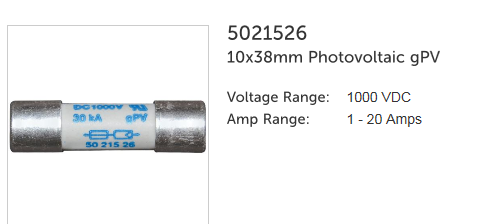
I had same problem with fuse, I placed an order with Mitsubishi Dealership here in WA, But they said it would take a week to get the stock from SA. Maybe I grabbed the last one in stock in WA. So I did not want to wait for that to arrive to start testing, so in the meantime, I contacted one of the local Electrical Wholesalers that supplies to the solar industry, and bought one of their 20amp 1kv rated fuses and the fuse holder. The fuse holder is for a DIN rail, but I just made up wires with ring terminals that would connect to the mounting screws of the original fuse, and then ran the wires to this new fuse holder, which pushes down and fits next to original location. Here is what the fuse and holder look like:
oIlGuf0.png


Here is the fuse:

xoIyOtI.png
 
For the 4.7R resistor that I found blown in the doghouse, I found a DIGIKEY A102487-ND
This is rated at 7 watts, and has same axial 5mm pitch mounting and 14mm width so it looks
quite simular to the original part.

For the relay, I found a DIGIKEY Z6355-ND Which is an OMRON G2RL-1AE-ASI
I made the mistake when ordering this, as I got carried away with the -ASI Suffix that notes it can handle 51 amps in rush current.
The draw back, is that this one only has a single set of contacts, so only two of the four contact pins come out and go into the PCB.
The original relay was more like a G2RL-1A-E-DC5 Which has two sets of contacts, so if one pair fail, the other set that is parallel
would still work. Both of these have a 16 amp contact rating.
 
@ sky

it this in your latest repair unit(#2) Post 1, List 17., or the previous one(#1),Post 1, List 13? maybe we need to come up with a designator to identify and avoid confusion.

When are you thinking that the 4.7R ceramic and/or relay contacts were damaged--was it after your repair job or part of the initial failure?

Thanks for posting the part number, i thought it was a TAM 5K series, but the 7K is better, rated to handle 70W for 5 seconds but no internal fuse such as in the P10K.

7K datasheet

P10K datasheet

Possible replacement ceramic resistor, TWW series from Ohmite, $0.89 when in stock
https://www.mouser.com/ProductDetail/Ohmite/TWW5J4R7E?qs=z79jz7UT1LesC4HOVACM7Q%3D%3D

i haven't checked the contact resistance in jray's box yet, but that is a good idea and easy to do, thanks for the idea.


@electron

it may take some time for the fuse to come in, but it may also take some time to figure out why it blew--just replacing a blown fuse will usually result in needing to order another fuse unless the root cause has been discovered.
 
Hi KIEV:
All of my posts from 29th of August onwards are regarding this 2nd OBC 17 SKYLOGGER#2 that I've been working on.
The first OBC 13 had the Twisted 39k resistor, blown 2x 1000pf caps in the doghouse and the 20 amp fuse in MCU Blown.
That was all that was required to get it running again.

So far on this 2nd OBC 17 SKYLOGGER#2 , the 20 amp fuse in MCU was blown, the 2x 1000pf caps in doghouse blown, one of the 4.7R resistors in the doghouse was blown, and the Relay in the doghouse you could hear click on activation, but contacts would never close to zero ohms.
I think that once I replaced the fuse, and 1000pf caps, I tried testing in car, and it seemed to detect AC input for a few minutes but then stopped charging. There is probably still some shorted component that is causing more than 16 amps to be drawn, which has now damaged the 4.7R resistor and the Relay during that test. Once I get the replacement relay and resistor replaced, I'll still need to see what other fault is causing the input current to be too high. Earlier, Coulomb suggested using a current limited power supply with an AC output of around 50v
applied to the AC input of the OBC. Buying one of these is not in the budget just at the moment. I have a few 2:1 mains transformer that get used to convert 240V to 120v which was used on some USA equipment to be used in Australia. I was thinking of putting 2 of these one after the other, so I end up with 60vac that I could put a 5 amp fuse in series with. Another thing that I was thinking about trying, is a portable "stick" arc welder. This is basically just a variable transformer with an adjustable output that max at around 50v. I could either leave in or take out the rectifier, and connect the output with a 5 amp fuse to the AC input of the OBC.

Before I try any of these things, Now that I have the waffle board removed from the main board, I'll continue ohming out the areas that I could not get to previously. Its a shame that in the final rectifier bridge section, there is a point where the two bridges are connected together, but there is no test point that can be accessed due to potting in the waffle. I guess that since I can go across the whole bridge array and see a 2x diode drop, that would look like something else if any of the 4 inside diodes were shorted. I was worried that one of these diodes would get damaged by the same inductive kick that killed the 2x 1000pf caps since the output filter feeds back to them. So far that all looks ok on the meter.

I can see a normal diode drop across the protection diodes that are across the IGBTs, but that's not much of a full test. Since the waffle is seperated from the PCB now, I was wondering if I used a 12v supply with a 10k series resistor connected to the gate of the IGBT, would a ohm meter show a difference across the output of the IGBT pins comming out of the waffle, or would I need to setup some other pullups or pulldowns to get a bias?
 
skylogger said:
I think that once I replaced the fuse, and 1000pf caps, I tried testing in car, and it seemed to detect AC input for a few minutes but then stopped charging. There is probably still some shorted component that is causing more than 16 amps to be drawn, which has now damaged the 4.7R resistor and the Relay during that test.
Initially, I thought that the resistor or relay failure might have been the original cause of the charrger failure. But with a little thought, I agree with most of your assessment. I think that the 4.7 Ω resistors must have been intact for the test, and failed after the few minutes. Hence, no more AC detection. But I think that the relay contacts may have been burned before the test. The pre-charge resistors allow the 3 220 μF capacitors to charge and the charrger to actually charge at very low power, but of course they will drop way too much voltage as the current ramps up. In fact, maybe the relay is the only problem now, apart from the extra 4.7 Ω resistor, and when these are replaced, it might all just work. But of course, it would be good to gain confidence about this. Replacing the relay means the full power of the mains is available for blowing up IGBTs :shock:

Once I get the replacement relay and resistor replaced, I'll still need to see what other fault is causing the input current to be too high.
As indicated above, I think there's a moderate chance that there isn't such an other fault. The normal mains current of over ten amps is too much for the resistors, if the relay isn't shorting them.

Earlier, Coulomb suggested using a current limited power supply with an AC output of around 50v
Actually, I use around 50 V DC. The charrger doesn't care; it will rectify whatever you give it. I was going to say that a ~37 VAC source (remember that 50 V will rectify to some 71 VDC before diode drops) isn't nearly as safe as a current limited DC source, but due to the 3 220 μF capacitors, the current limiting will have little effect. The capacitors with enough voltage will have enough energy to destroy the IGBTs before the current limiting can come into effect. Perhaps you could use a 12 VAC or even DC plug pack to connect to the mains. There isn't a lower limit, because the power supply doesn't come from the mains, but from the auxiliary battery. In fact, you might be able to use your 13.8 VDC power supply to power the mains input and also the 12 V input, wiring them in parallel. There should be isolation to prevent problems with that. Unfortunately, without intervention, the PFC front end will probably work really hard and turn that 13.8 VDC into ~400V for the IGBTs to switch. The Elcon/TC charrgers had mains detection, and disabled the PFC section if the mains was not detected. We don't know if these Nichicon charrgers have this detection and disabling.

I guess that since I can go across the whole bridge array and see a 2x diode drop, that would look like something else if any of the 4 inside diodes were shorted.
Yes, the fact that you can't separate the two paralleled bridges doesn't really matter at this point. As you say, any single diode shorting should be detectable.

I was worried that one of these diodes would get damaged by the same inductive kick that killed the 2x 1000pf caps since the output filter feeds back to them. So far that all looks ok on the meter.
Excellent point. But I think the IGBTs have a reasonable surge current rating, so they might survive where the capacitors literally explode.

I can see a normal diode drop across the protection diodes that are across the IGBTs, but that's not much of a full test.
True, but considering the usual failure mode of IGBTs (total meltdown and short circuit, or alternatively fused bond wire and hence open circuit), seeing these normal voltage drops is quite a good sign. I'd say very roughly a 75% confidence that they are OK.

Since the waffle is separated from the PCB now, I was wondering if I used a 12v supply with a 10k series resistor connected to the gate of the IGBT, would a ohm meter show a difference across the output of the IGBT pins comming out of the waffle, or would I need to setup some other pullups or pulldowns to get a bias?
That sounds reasonable; I think it should work. You might have to come down a bit with the 10k series resistor; there may be something like a 10k pulldown from gate to emitter already. Though I've seen values as high as 47k. 1k from 12 V (12 mA) isn't going to blow up these large devices. I'd use the diode range on the multimeter, rather than ohms; often ohms range are designed to be lower voltage so as not to turn on semiconductors, and diode ranges are higher. My second hand Fluke can even slightly light up blue LEDs (near 3 V). I just used another multimeter to check it: 0.15 V on the ohms range (auto ranging, so that's the 40 megohm range), and 3.76 V on the diode range. Other multimeters may not have as large a difference, but still.

[ Edit: "merely work really hard" -> "probably work really hard" ]
 
Thanks for clearing up the question about which OBC you were testing.

i think coulomb was suggesting that you can use a DC power supply of about 50-60 VDC with an adjustable current limit in order to make probing measurements and not cause additional damage--an AC supply is not necessary. The DC will pass thru the diode rectifier bridge and charge up the 3 big caps, then the PWM switching of the Boost stage can be measured or seen on your scope to prove that it is working. Hopefully your waffle plate is intact and undamaged.

Your data and findings re-affirms my thoughts about a weak Aux battery.
If the 5V coil drive supply gets drop-outs due to a poor 12V supply, then the contacts in the AC input relay would be experiencing excessive chatter and internal arcing which coats the conductive contact surface with carbon. Now it is a high-resistance contact and eventually the relay wasn't carrying any current, but it was routed thru the two 4.7R precharge resistors. Those are fairly tough resistors, but they weren't sized to handle the full current required to operate the OBC.

In addition the AC detection circuit picks off the AC signal downstream of the relay contacts--the cutting in and out of the OBC during your test was a sign that the relay contacts were frosted and the processor was getting confused. If you pull the DTCs with the MUT i predict you will have a stored code in the EV-ECU for
either:
Code No. P1A10: On board charger power supply relay circuit, low input
Code No. P1A11: On board charger power supply relay circuit, high input

If you could read the OBC data items the code would be either 06 or 27, for abnormal AC input voltage or current, or taken from the FSM:
=============================
Code No. 04: Control Power Supply Voltage Abnormal. This is recorded if:
For more than 10 seconds, the on board charger control power supply voltage is less than 7.2 V.
or
For more than 10 seconds, the on board charger control power supply voltage is more than 17.6 V.

Code No. 04 PROBABLE CAUSES:
The auxiliary battery is failed.
When jump-starting at more than 17.6 V from the outside of the vehicle.
The installation of the auxiliary battery terminal is failed.
The DC-DC converter is failed.
Open circuits of on board charger power supply, short circuits to earth or damage; poor contact of connector
The on board charger is failed.
==========================
So my thoughts are pointing to weak or old Aux batteries as the main culprit common to all these failures on the forum. The specific manifestation of burnt and blown parts is related to which cascade of events gets triggered.
 
skylogger said:
The part number on the relay is K1AKOO5W-KW I soldered some wires to the coil pins and supplied 5v to the relay and could hear it click.
Hopefully you were careful to get the polarity correct; there is likely a diode or other circuitry across the relay coil that could be damaged by a low impedance 5 V power source if connected the wrong way around. It's a significant pain getting these relays off the board, so testing in-situ is a good idea.

Something to keep in mind if other readers attempt this sort of thing.

Also be aware that giving power to the relay may also liven up the whole 5 V circuit, which may have consequences. So make sure you have no other power connected when you do this, or gates could start turning on, etc.

Another consideration is that if the relay doesn't pull in, it may be because something else is dragging the 5 V supply down. This was especially the case with the Elcon/TC charrgers, which ran the relay off the 15 V power supply (via a 68 Ω resistor), and plenty of other power gear (gate drivers, PFC chip, PWM chip, and a quad NAND gate) would often effectively short out the 15 V power rail.
 
kiev said:
Code No. 04: Control Power Supply Voltage Abnormal. This is recorded if:
For more than 10 seconds, the on board charger control power supply voltage is less than 7.2 V.
or
For more than 10 seconds, the on board charger control power supply voltage is more than 17.6 V.
With the 17.6 V figure mentioned twice, it sounds like these error codes respond to the voltage of the auxiliary battery, as read near the charrger input. That seems to imply to me that they expect the charger to work more or less successfully down to around 7.2 V. I find it a stretch to imagine that an auxiliary battery that operates window winders, headlights, etc well enough to not be immediately suspect would fall to 7.2 V while charging. However, the sudden switch-on of a coolant pump or the like might cause a brief brownout, which might cause the relay to partly drop out. But a relay that pulls in at less than 5 V will likely not drop out at more than ~2 V, so I'm still a little sceptical.
 
i bought my car ~ 3 years ago and it was only ~3 years old at the time, and it still had the original OEM 12V Aux battery. i drove it the first year without doing any maintenance or worry, but sometime into the 4th year i started having troubles. The car would randomly quit and throw the HV ! warning, go to turtle mode and other weird stuff. i might have to try several times to re-start, leave the key off for several minutes then re-try etc. No pattern developed to give any clues of why this was happening.

i checked the Aux battery and it was reading ~12.8 OCV, so it seemed ok to me--i kept driving it and putting up with the occasional stall which was becoming more frequent. It was bothering me and very troubling that it could just die for no good reason while on the road...not a good thing in traffic.

Eventually i decided to just get a new Aux as part of the troubleshooting process--it was still reading "good" at OCV, but i was getting desparate. And the new Aux seemed to solve that issue, no more stalling. i think some other folks were having the same random issue around the same timeframe, same year car, same OEM Aux, etc.

So now we are seeing 17 OBC failures within the past 6-8 months. The poll results are not complete, but i suspect a commonality that those with failures were still using the original 6 year old OEM Aux battery.

i got a report this week of another OBC failure from someone not on the forum--they replaced his 6 yr old OEM Aux battery as part of troubleshooting, but the OBC is bad. Price is too high, the car is for sale.

It may be difficult or impossible to prove the weak Aux battery theory, but my stalling experience and its resolution leads me down this path. i will keep an open mind and i'm willing to test other theories and look for bad parts and the smoking gun...

But if you are still using an old Aux, please save yourself grief and get a new one before the something hits the fan...

Here's the link to FSM for this code, there are strange phrasings due to translation from Japanese to English:
Code No. 04

Also a link for testing the 12V AUX battery.

They have a three-part criteria with an open-circuit, charging, and loaded voltage test.
It must have a no-load OCV of 12.4V two minutes after running the headlights for 15 seconds, and
It must be have OCV of 12.4 or more after 6 hours of charging at 5 Amps, and
Under load it must measure higher than a minimum temperature-dependent voltage ranging from 8.5 to 9.6V (-15 to +21C) after 15 seconds of discharging @130 Amps.
 
I cannot collaborate this, as it is only the sellers word, but when we bought the car, he said that he had the Aux Battery replaced because the car would not power up. So the battery is supposed to be about 1 year 4 months old, the battery indicates it is good, but the battery is rather tiny. So possibly it is undersized for the car, which may be why we are seeing this issue in our car a year after purchase, hence why I want to buy a larger AUX Battery.

I am about to drain the coolant in our car, and remove the DC/DC Converter, remove it and the upper board and start the diagnosis of the DC/DC Converter. So now for a recap on we know about our car so far.....

  • We have both snubber caps on the riser board blown
  • We have the MCU Fuse blown
  • Our BMU was replaced by Mitsu at our expense :/
  • We have the MCU Fuse on order (4 weeks delivery)
  • We have replacement snubber caps on order, should arrive next week.

So from everyones experience thus far with diagnosis and repair of the DC/DC Converter, what is the recommended diagnosis process.

Do we need to remove the black stuff in the dog house, or can we mount the new snubber caps on the riser (I know the rise is for SMD, not sure if it is possible to retro fit through the hole onto it or not).

Do we need to remove the board from the waffle plate, or can we do the diagnosis and repair with it attached to the waffle plate?

Can the board with the dog house etc be removed without desoldering?

Also I have a bench top lab power supply, multimeter, can I use this for testing. I also have a 2 channel oscilloscope, as well as a good Hakko solder station. I do not have a rework station, but we do have a rework station at uni (electrical engineering school).
 
kiev said:
i bought my car ~ 3 years ago and it was only ~3 years old at the time... Eventually i decided to just get a new Aux as part of the troubleshooting process--it was still reading "good" at OCV, but i was getting desperate. And the new Aux seemed to solve that issue, no more stalling.
Yeah, that's interesting. Something crazy must be happening with the 12 V system when the auxiliary battery goes weak.

Here's the link to FSM for this code, there are strange phrasings due to translation from Japanese to English:
Code No. 04
That brings up another possible culprit: the A-06X relay (not the mains relay inside the OBC, the one with many fuses nearby that supplies 12 V to the charrger). A combination of heat, vibration , age, dirt and moisture might have affected this component or its socket (if it has one). Maybe the OBC doesn't draw enough current to "wet" the contacts and keep them clean, though I think that's about 20 mA, surely it would draw that. If it gradually built up a layer of oxide, it might make the OBC more sensitive to marginal auxiliary battery condition. In fact, it might be more effective to replace a $5 relay than a $100 auxiliary battery. Just a thought, though I have no idea how to test it. Maybe put a multimeter on the charrger input and tap the relay with a screwdriver, perhaps wiggle it in its socket (if removable).
 
That's a really good idea, the relay is located up front in the fuse/relay tray. There are numerous tiny relays, closely packed in the tray and they are difficult to grab and remove. But if an OBC has failed in a car, then it makes a lot of sense to swap out the little A-06X relay also.
 
Hi Coulomb:
I'm glad we have these little chats, Too bad I did the relay test, before I discussed with you what I was going to try.
I did see that the relay coil (on the relay itself) was not polarized, and I had the top PCB disconnected, and the waffle board removed,
so I did not think polarisation of supplying a test voltage to the relay coil would matter. Turns out, the protection diode D301 is still there, just to the side of the doghouse, so I managed to blow that up when I tested the relay. Good thing that its just the relay, the D301, and Connector CN1 Involved (since the top PCB was not plugged into CN1 at the time) so I'm sure nothing else got damaged. I pulled a SMD Diode off another scrapped piece of equipment and replaced D301, So when the relay comes in from Digikey I should be back to square 1.
So kids don't try this at home unless you are a trained professional :) or at least get the polarisation correct.

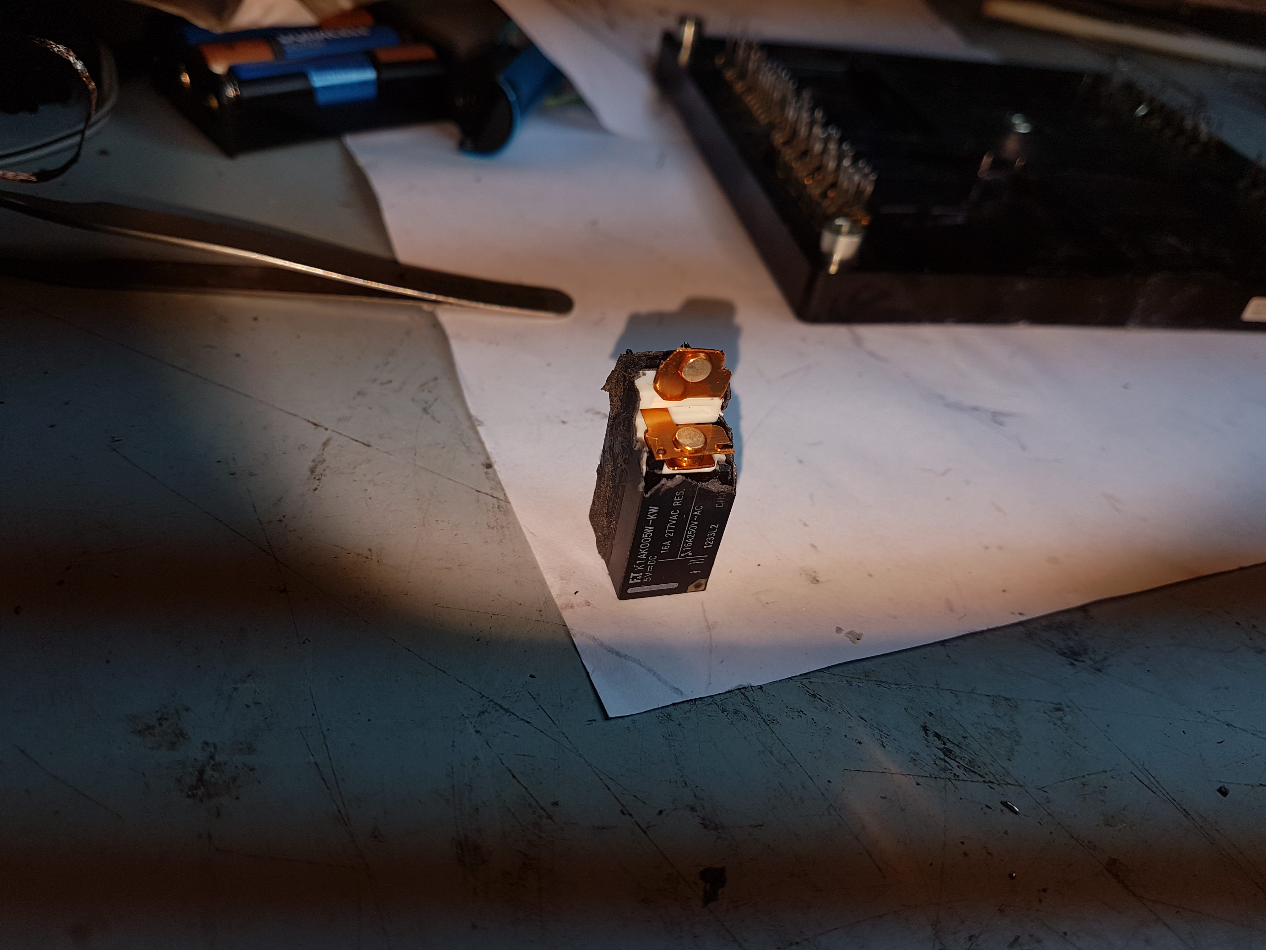
I did a post-mortem on the relay that was in the doghouse. I bent the contact back so you could see both contacts.
It looks like there is no obvious burnt contacts, but if you zoom in, there looks like a bit of oxidation.
Also I thought this relay had two sets of contacts and they were being used parallel so there was some redundancy,
but now that I have chopped off the top of the relay, I see it is a Single Pole Double throw. Out of the four PCB pins for the
contacts, One of the pins is a Not used. The PCB is laid out so that the Normally closed pin is connected to the centre contact pin, and the
Normally open pin is is connected to the not used pin. If I had not already got it on order, I would have probably ordered a different version of the relay that was double pole single throw, so there would be two sets of contacts in parallel and offering some redundancy on the same PCB footprint. Here is a photo of the contacts:
DhvlZKy.jpg
 
Back
Top