The Troubleshooting and Repair for On-board Charger (OBC) Thread

Mitsubishi i-MiEV Forum

Help Support Mitsubishi i-MiEV Forum:

This site may earn a commission from merchant affiliate links, including eBay, Amazon, and others.
Hello, since 2013 I am an enthusiastic i-Miev driver. Some weeks ago my DC-DC Converter had a damage like on page 33 in this forum. I followed the advices and the on-board Charger worked again. Thank you very much!!!!

http://i.imgur.com/gallery/pOPmH0J.jpg

After a few days, while my car was being charged, the fuse of our house was triggered by our high pressure cleaner and from this moment, the Charger does not work anymore. :shock:
The first thing I checked was the items I had changed before, but they were not damaged. Then I checked the 12V-battery. During the "ready"-phase the voltage was 14,4 V. So I think the DC-DC Converter is working.

When I connect the Charger, the loading process starts for a few seconds and then it is interrupted. In the cockpit I see the yellow car with an exclamation mark.

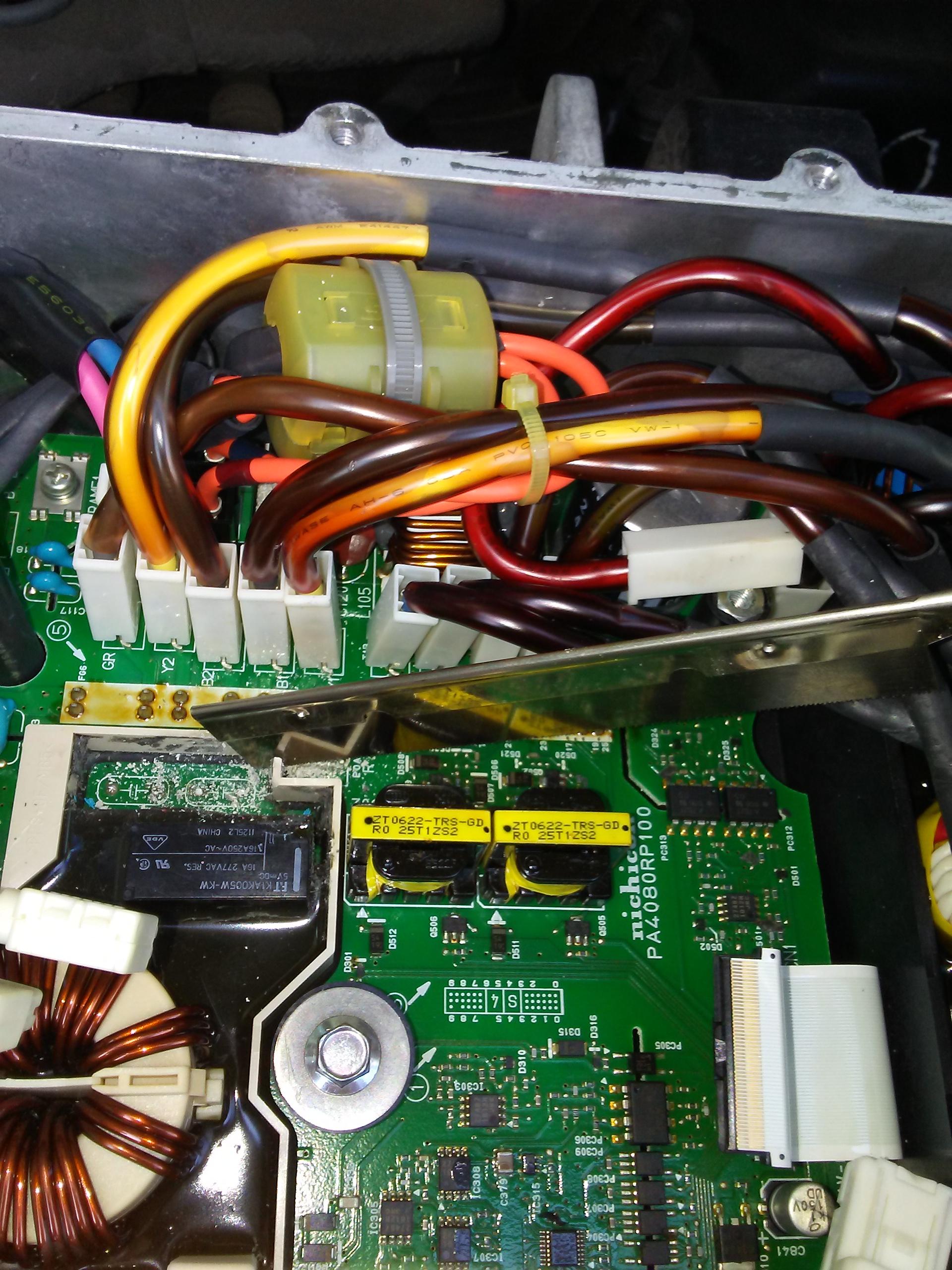
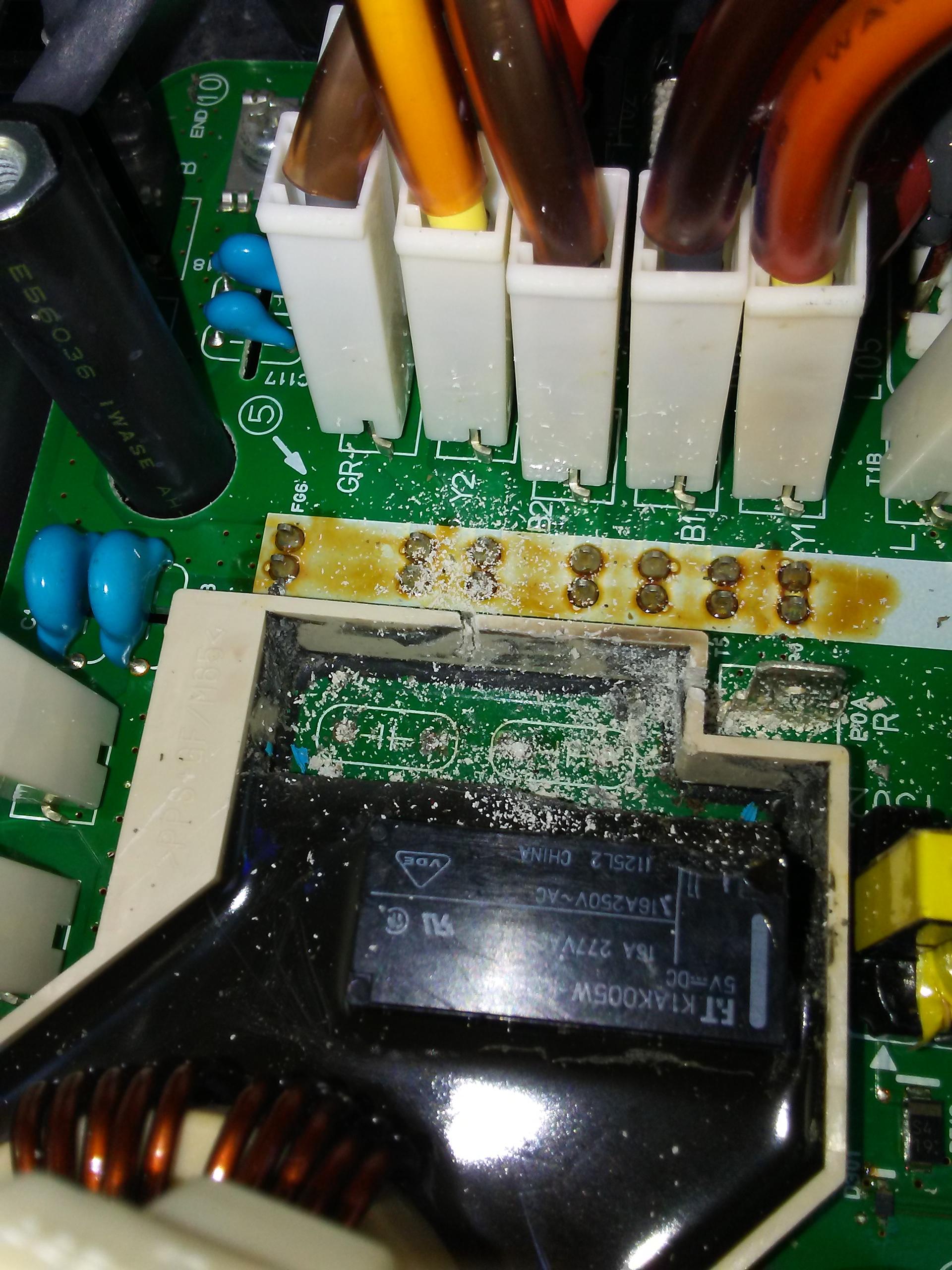
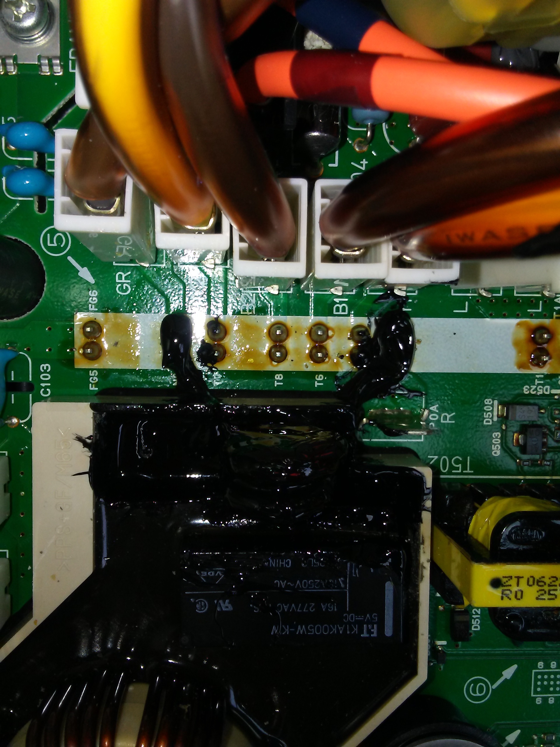
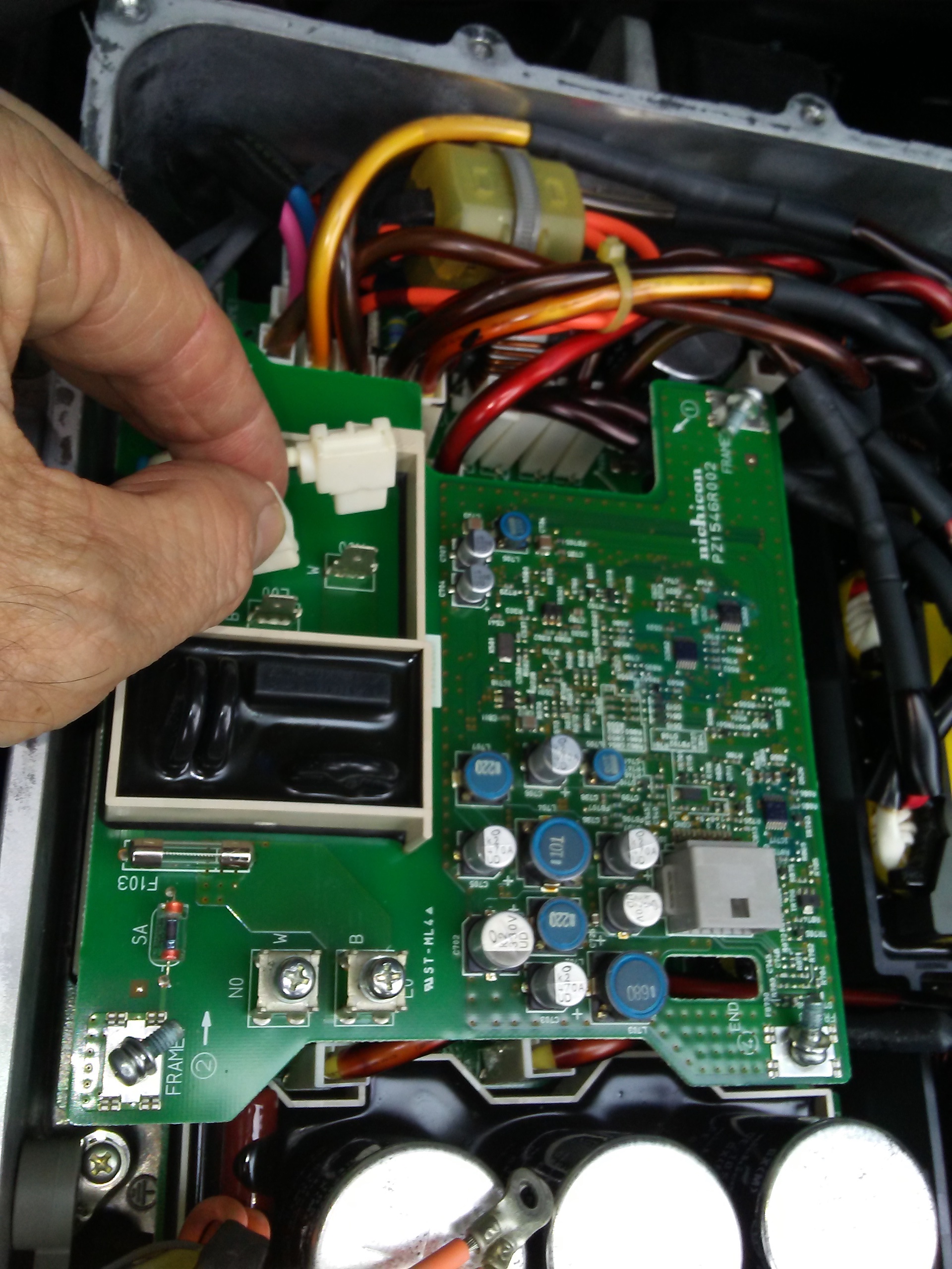
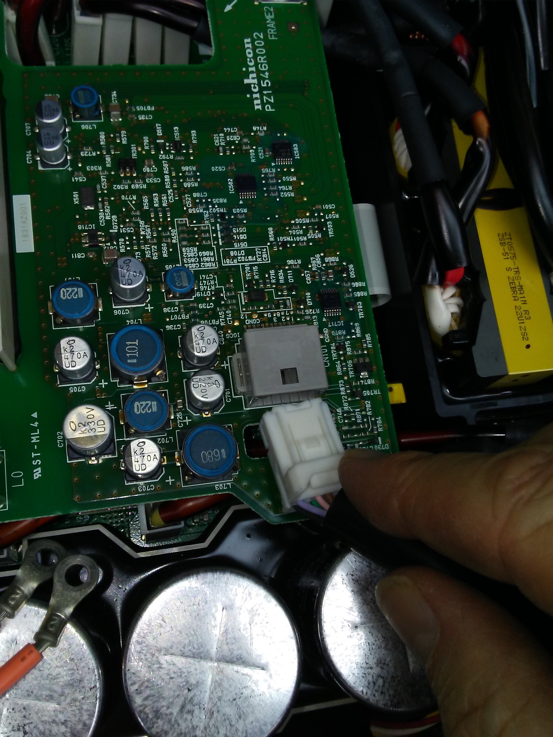
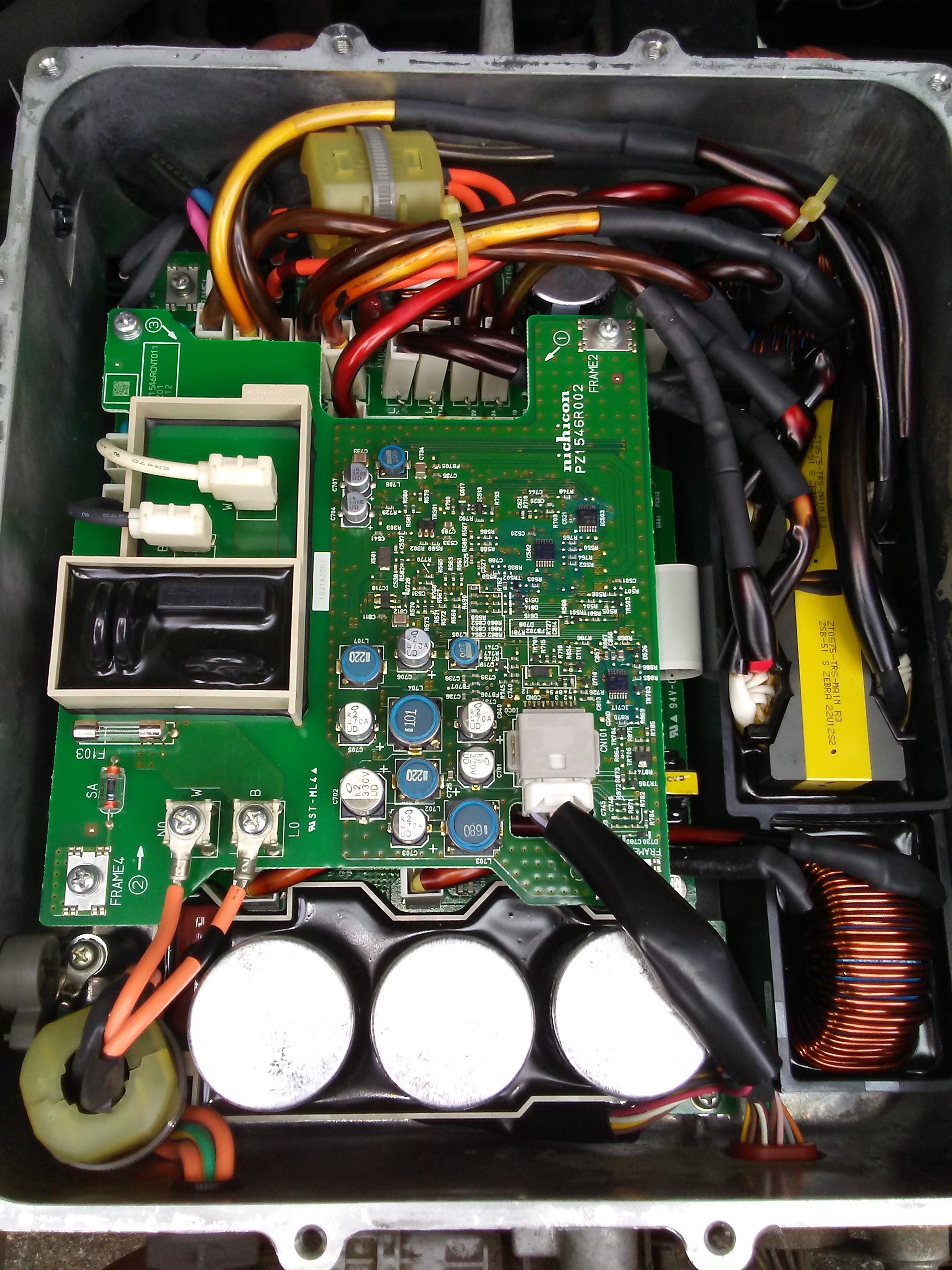
After separating the platine from the waffle board of the Charger, I see that four elements within the black material in the under right quadrant of the waffle board were blown off.

http://i.imgur.com/gallery/rPtszTv.jpg

https://i.imgur.com/gallery/CmZjSYK.jpg

My question to the specialists is now: Which components are there under the hard epoxytype potting compound and can I change these elements??????

Or better:

Does anybody have such a waffle board (which works) to sell??????

Thank you for your help...
 
Harw40 said:
I thought I’d take the $25 gamble. I didn’t try charging but went instead to ‘ready’ where my hopes were dashed with an audible pop from the rear of the car.
Huh. So that's evidence that some of the problems happen after the fuse goes open circuit. But I'd like to be clear on the exact sequence of events if possible. It sounds like the first symptom (warning lights) happened after starting the car. Then you could not charge any more, but there were no pops or other changes in symptoms till you replaced the fuse. Then the first time you went to ready, with no AC power connected, after replacing the fuse, there was the pop from the rear of the car. Did I get that right?

... have extracted the obviously damaged components. They are one of the blue ( m&m size) ‘snubber’ caps, which had split open; the Okaya LE 225 capacitor which had bubbled on the 7K resistor side, and the 7K resistor itself that may have been ok but I extracted anyhow as it looked baked next to the Okaya bubble.
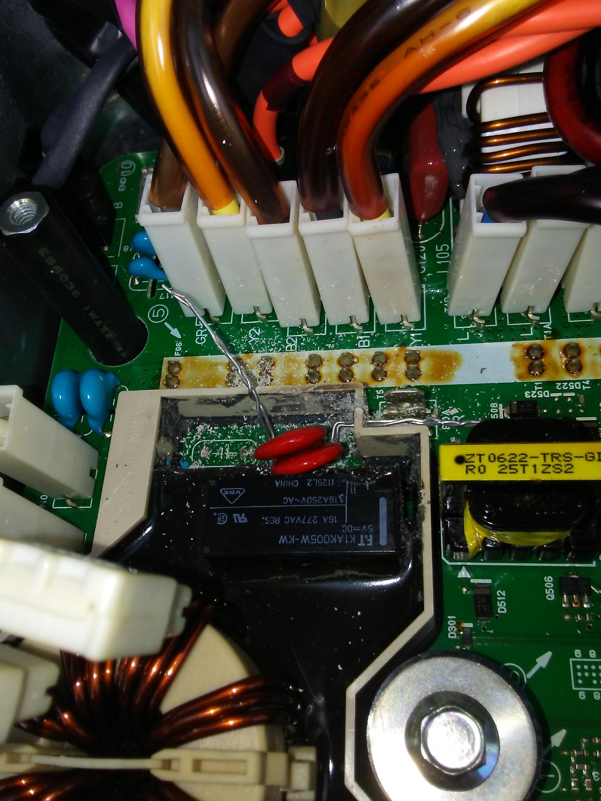
I'd say that the capacitor was damaged from the "7K" resistor (actual resistance is 4.7 Ω), not the other way around. So I think replacing the resistor, even if it measures OK, is a really good idea. Actually, the P10K (also 4.7 Ω but with a fuse included) gets the same current, and therefore since it has the same resistance gets the same power, might also benefit from replacing, but it's physically a little larger, so it may handle the same power load better.

My guess is that the pop would have been from the "M&M" splitting; the resistors would suffer in silence, I would think. I wonder if the resistors were getting hot before the fuse failed, or overheated as a result of the capacitors dying? I would think that they would fail open circuit, and even if they failed shorted, that's still a low power situation.

I do wonder if putting a new fuse in and giving it another go caused further damage?
It's sounding that way.

Questions; will I be able to solder reliably from above to the legs sticking up?
You should clean the protruding pigtails as best you can, and pre-tin the pigtails of the new capacitors, and solder as quickly as you can.

Can anyone inform me of the polarities for these three pieces
None of them is polarity sensitive. AC components never are, as they experience polarity changes all the time.
 
fabele said:
I will check the 12 V battery and the 14.6 V in the ready state , but i think it must be in good condition, as it drives the other electic parts such as, e-windows ...
It would seem that way, but in fact an auxiliary battery seems to need more than just enough oomph to operate windows etc.
Before open it what to do for safety. ( inside of the box the 360 V is there).
Yes, always pull the service plug before opening a box that might have 360 V inside. Search for posts about where to find this.

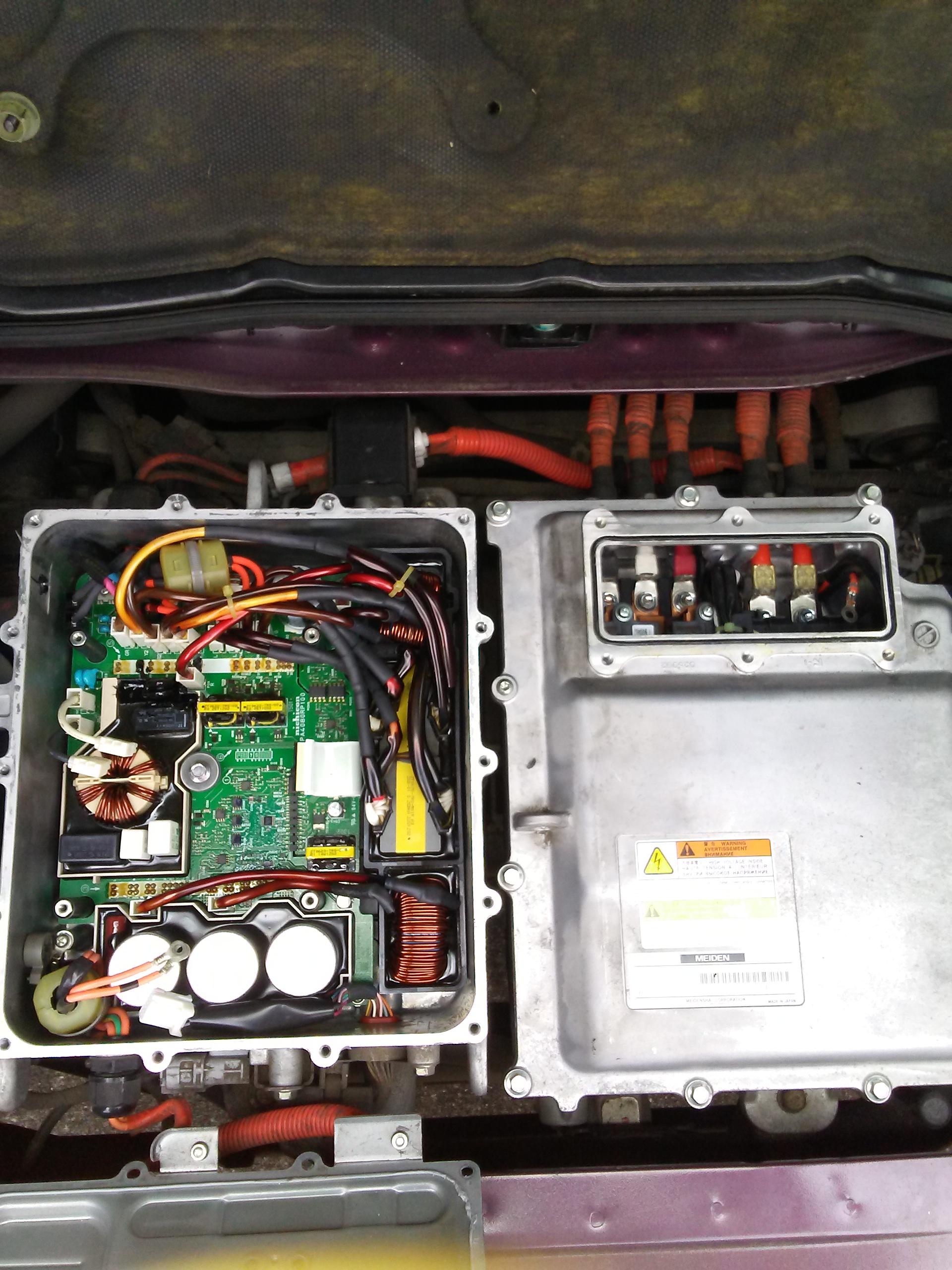
The MCU ( the motor control unit ?) is just right on the top of the motor?
Yes, just to the right of the OBC / DC-DC box.

If the car funtioning perfectly can this MCU 20 A fuse blown?
Yes, another confusing thing. The fuse for the OBC and DC-DC is locate in the box with the motor controller. There is a little access panel to gain access to that fuse without opening the whole motor controller box.

Opening any box what is the best way to make a perfect insulation after fixing the problem? ( if i do it wrong it may cause serius problems to the electronics).
I don't get what you're asking here.

It will not be easy to find a new capacitors if this will be the problem, (maybe e bay?)
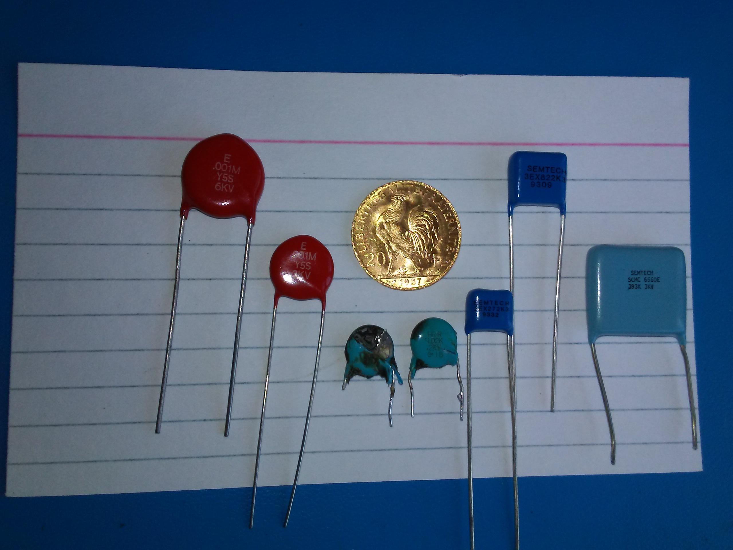
There are part numbers etc. in the index (first page), under "Pictures and specs for blown snubber caps".
 
Malte said:
I followed the advices and the on-board Charger worked again.
Well done!

After a few days,
Eek. But tragically short-lived.

while my car was being charged, the fuse of our house was triggered by our high pressure cleaner and from this moment, the Charger does not work anymore. :shock:
Well, that' more evidence that suddenly interrupting the AC power is not good for the charger. Though in this case, with a highly inductive motor involved, there may well have been an unusually large voltage spike to go with the sudden interruption.

After separating the platine from the waffle board of the Charger, I see that four elements within the black material in the under right quadrant of the waffle board were blown off.
Yikes! That's the first time I've heard of someone blowing components in the Waffle Plate™. You're a pioneer! :eek:

My question to the specialists is now: Which components are there under the hard epoxytype potting compound and can I change these elements??????
Those appear to be the main switching IGBTs. We don't know their part number, and no-one that I know of has attempted to remove the epoxy. It looks like hard epoxy, which may have to be softened in an oven, or with a tool like a reflow soldering tool that can direct heat to a small area.

Would you be willing to give it a go, perhaps reporting any part numbers that you can recover? There are 8 IGBTs involved, they'd all be the same part number, and it looks like only 4 have been badly burned. I'd guess that all 8 will need replacing (al 8 should cost well under US$100), but you might be able to recover the part number from one set. We're hoping that under that epoxy there will be a single sided PCB (perhaps extra thin fibreglass) with extra thick copper traces, with normal surface mount parts soldered to it. But you may find spot welded parts or other headaches. I wondered if the components might be contained in large square holes punched in the PCB, so the components could thermally bond to the heat-sink plate, but the X-ray photo doesn't seem to suggest that.

Or better:
Does anybody have such a waffle board (which works) to sell??????
I think your chances there are very low, unfortunately.
 
coulomb said:
fabele said:
I will check the 12 V battery and the 14.6 V in the ready state , but i think it must be in good condition, as it drives the other electic parts such as, e-windows ...
It would seem that way, but in fact an auxiliary battery seems to need more than just enough oomph to operate windows etc.

Before open it what to do for safety. ( inside of the box the 360 V is there).
Yes, always pull the service plug before opening a box that might have 360 V inside. Search for posts about where to find this.

The MCU ( the motor control unit ?) is just right on the top of the motor?
Yes, just to the right of the OBC / DC-DC box.

If the car funtioning perfectly can this MCU 20 A fuse blown?
Yes, another confusing thing. The fuse for the OBC and DC-DC is locate in the box with the motor controller. There is a little access panel to gain access to that fuse without opening the whole motor controller box.

Opening any box what is the best way to make a perfect insulation after fixing the problem? ( if i do it wrong it may cause serius problems to the electronics).
I don't get what you're asking here.

It will not be easy to find a new capacitors if this will be the problem, (maybe e bay?)
There are part numbers etc. in the index (first page), under "Pictures and specs for blown snubber caps".


Could you to help me to find the place of the service plug. I searched in this forum, but did not succided.
The cover of the OBC is fixed not only mechanically with screws but it was used a special waterproof material (glue??) against the water and dirt to get in the box.
 
Could you to help me to find the place of the service plug. I searched in this forum, but did not succided.
The cover of the OBC is fixed not only mechanically with screws but it was used a special waterproof material (glue??) against the water and dirt to get in the box

It's under the left front-seat under a around 20cm big metal lid.
The plug looks kind of like a Makita electric screwdriver accu.

Please don't open any box before finding the plug!
 
Malte said:
Could you to help me to find the place of the service plug. I searched in this forum, but did not succided.
The cover of the OBC is fixed not only mechanically with screws but it was used a special waterproof material (glue??) against the water and dirt to get in the box

It's under the left front-seat under a around 20cm big metal lid.
The plug looks kind of like a Makita electric screwdriver accu.

Please don't open any box before finding the plug!

The auxillary battery is 12.7 V, but turn the system to the Ready state it is 12.4 V only.
 
@fabele

Your Aux battery measurements indicate that the 20A fuse in the MCU (under the little cover plate) has blown. It provides a path for power from the main pack to the DCDC converter, which if working then you would read 14.4V Aux during READY.

Based upon the experiences reported here, the snubber capacitors in the OBC have likely blown too.
 
To expand on and correct my initial post. It was my red battery light and not my brake light that came on with my amber ! / car light with one of my start ups in town. Had 12v battery replaced thereafter - the existing one ( original?) was load tested and I was told it measured @ 88% - but nothing changed with the car. I plugged in to both the original level one evse and a level two evse I purchased but with both I got the brief startup procedure of click and fan before shutting down. Charge light going off on dash.

I then tested the 20amp fuse and found it blown. I ordered two from the dealer and like I said previously ,decided to try simply swapping it out hoping it may have blown as a consequence of a weak 12v. No such luck as I heard a pop when switching on to ‘ready’ and still had the battery and ! Icons on my dash. I do wonder if trying another startup with a fresh fuse caused another one of my doghouse pieces to blow but it’s beyond me. I’m now left with replacing the three items hopefully from above on the legs I managed to save from the compromised pieces?
Again, I’m confused with regards to polarity . Looking at the capacitors from below on the top board I couldn’t ascertain polarity? I read that it should be marked on the board but ? .. With the bottom board still attached to the waffle plate I of course can’t even see underneath that one.

Kiev, thanks for the picture of a soldering suggestion for the ‘snubber’. Would you suggest that route even if you had the soldered legs of the original protruding from the bottom of the board to solder to?

Coulomb, in regards to my resistors, the 7K one with the slightly baked look next to the Okaya, when I broke it apart there didn’t appear to be a break in the wire coil embedded in the ceramic. Does this imply it was alright? and more to the point mean the 10K one is likely alright as well as I haven’t broken that one away ?
 
@Harw40

Thanks for the additional details about your OBC failure. We have ideas of the root cause but nothing definite, although lately i have been thinking that the MCU fuse is the weak link in the chain and may be the culprit to initiate all the damage. Other factors such as weak Aux battery, sudden loss of AC input power, etc. may also cause damage, but most failures involve the fuse.

One of the legs broke on my snubbers, so that's why i was looking at alternative mounting. Plus there are no solder pads on the top surface and i wanted something more robust.

The plastic walls of the doghouse are a soft plastic that is easily cut, i used an exacto saw blade to cut slits for the wires.

Dmo0Lhx.jpg


mHh904N.jpg


ow9pIwY.jpg


eN6uHYz.jpg


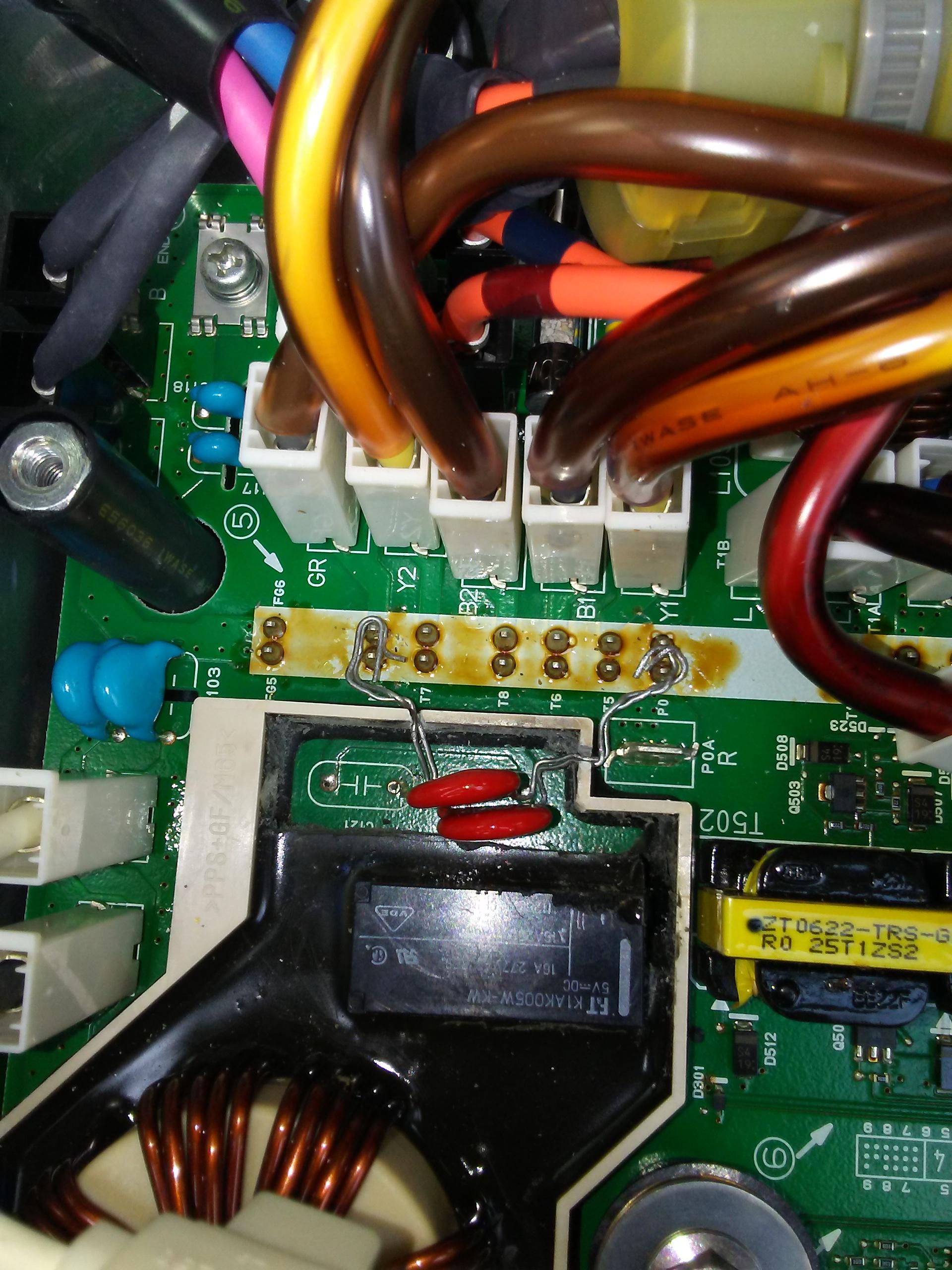
One broken leg on the blown snubber, but the other cap measured fine. There are high voltage rating caps out there from Vishay, Murata and others, just search for HV capacitors at digikey, mouser, etc.

kcgFSVD.jpg


edit: revised my routing again to directly solder the caps on the ends of the waffle plate solder joints. i have some liquid electrical tape compound from home depot that i will brush on to cover exposed wires, etc.

yj4LBcX.jpg
 
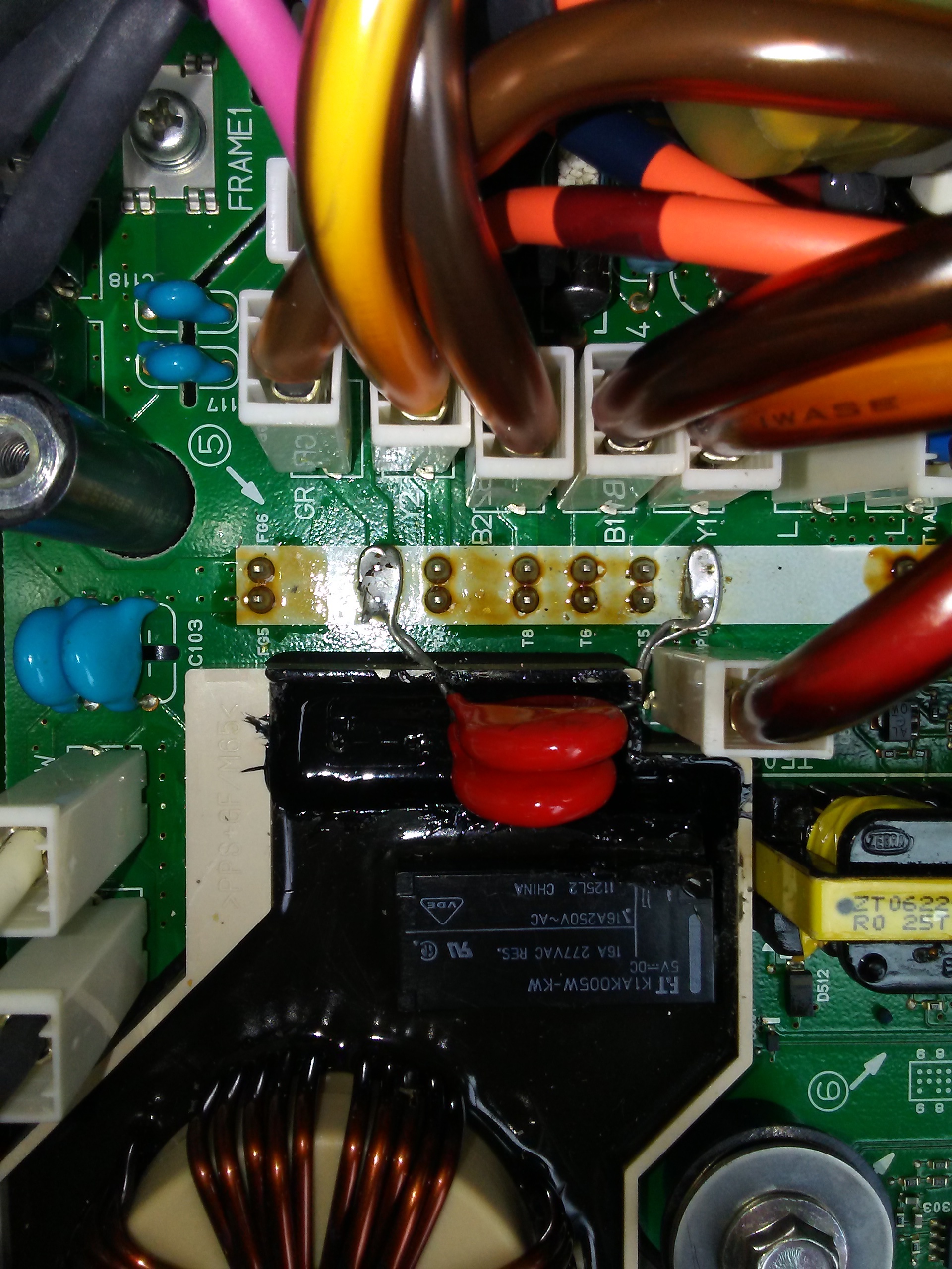
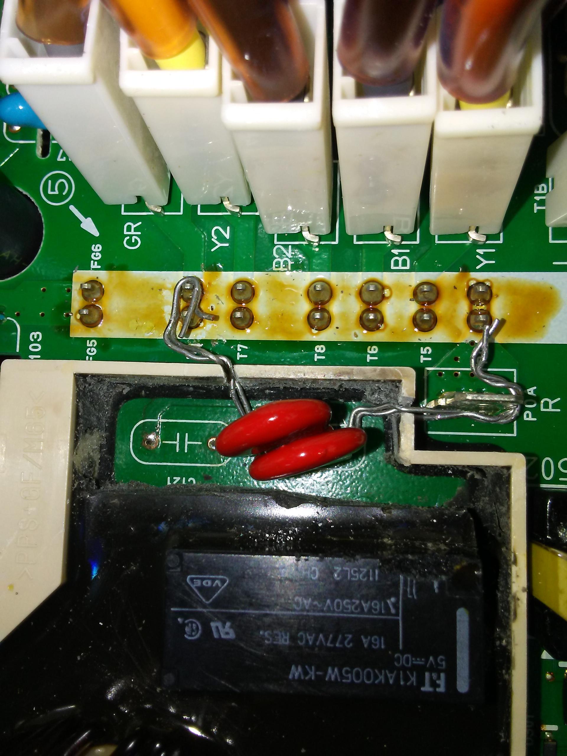
This was my final selection, i used the larger diameter 6kV-rated caps.

Cut slots in the walls of the doghouse plastic to route the leads to the PO and NO solder joints from the waffle plate.

Coated the inside of the doghouse with liquid electrical tape compound from home depot.

Carefully bent the leads while holding with needle nose pliers to not break the epoxy blends on the snubber caps.

Wrapped leads around the solder joints and then soldered it all together.

Coated everything with the tape compound. Waiting for it to dry, i think this will work and is a fairly easy repair from inside the OBC.

No need to remove the OBC from the car, nor the board from the box. i did not disconnect the service plug nor the 12V Aux, but i did remove the MCU fuse and disconnected the CAN buss plug from the OBC. i used a voltmeter to check and verify that there was no voltage present from the pack to the MCU during this procedure.

soldering completed:
xthABum.jpg


smothered and covered (wafflehouse slang) in the doghouse:
B2oGfOt.jpg
 
After soldering in the snubber caps, here is everything opened up:
oNjGAeQ.jpg


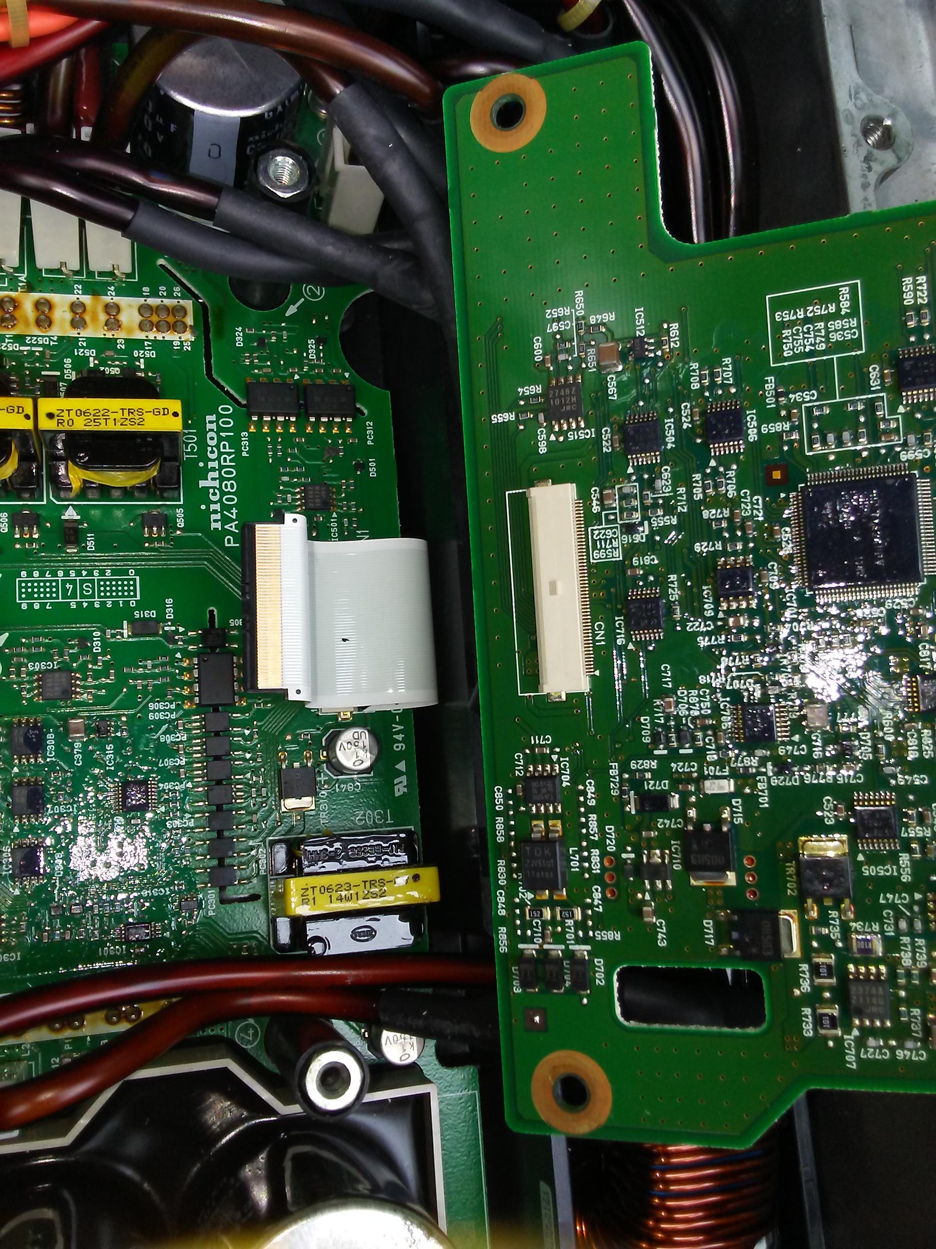
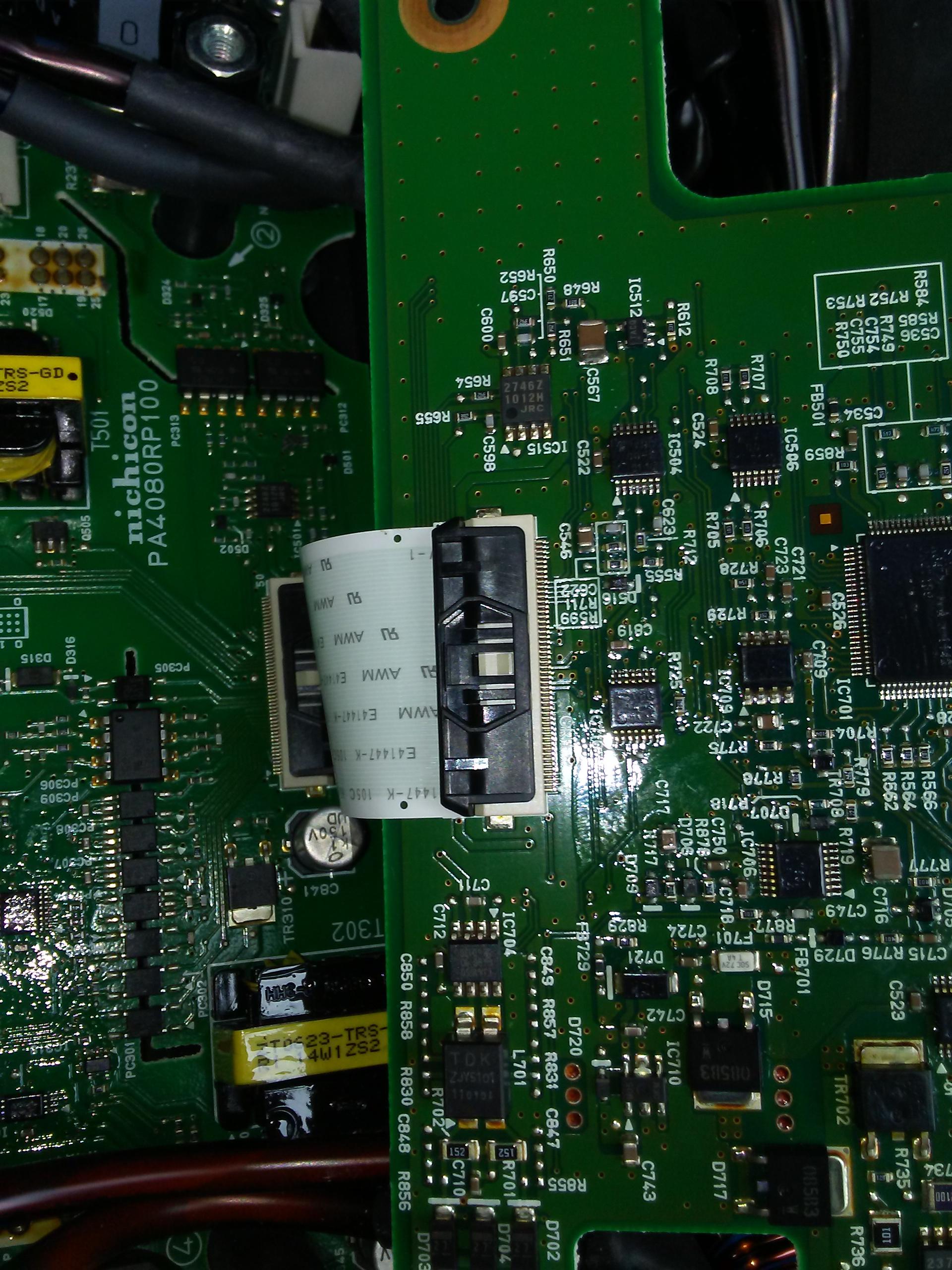
The top board must go back in:
LzkICo4.jpg


Slide the ribbon into the thin slot until it snaps:
qDMkhYv.jpg


Screw in the top board, connect the tabs:
fTfS8rG.jpg


CAN buss connector and AC mains lugs:
Nl3sOaY.jpg


All done and ready for the cover plate:
iDBvS8u.jpg


i just put a thin coat of grease along the sealing surface of the OBC and MCU access covers to seal the joint and keep out dirt and moisture.
 
Yikes! That's the first time I've heard of someone blowing components in the Waffle Plate™. You're a pioneer! :eek:

Ok, I'm proud to be a pioneer, but it does not feel very good here :cry:
 
Kiev, re the photo with the saw: nice "hacking" (almost literally :D ).

Would it not be possible to suck the solder from the holes from above with a desoldering station, and solder in the new parts from above? I guess many people don't have access to a desoldering station, but patient use of a solder sucker might do it. Or just leave the solder in the holes, and ease the new capacitors in a millimeter or two at a time, alternating sides.

I worry about clearance to other tracks with all those long leads.
 
Kiev,

re the temporary fuse: what's the thinking there? I'm really uncomfortable with a piece of wire to protect a 360 VDC circuit, even temporarily.

Especially when you've just been poking around and changing things.
 
Good point, i didn't have a replacement fuse so made the jumper for test purposes, but probably not a recommended practice.


So i thought it should be fixed, but no such luck.

i was able to start to READY, and drive the car, but still getting the same DTCs when trying to chargge. The fan and water pump run briefly as normal before chargging, but the start command is not sent according to monitoring with i909 scantool.

P1A12 - abnormal OBC stop. i909 will clear this EV-ECU code but it comes back. i909 will not read or clear OBC codes.

P0A09 - DCDC converter fail (1). i909 will clear this EV-ECU code but it comes back.

The Aux voltage was on the low side at 12.2 V, but came up to 14.1 when the car went to READY or the EVSE was plugged in.

So the DCDC converter is actually working, but the EV-ECU throws a DTC that it is failed.

Maybe these are leftover DTCs that are not really being cleared by the scantool, and require a real MUT ?
 
fabele said:
Thans for helping me.
I will check the 12 V battery and the 14.6 V in the ready state , but i think it must be in good condition, as it drives the other electic parts such as, e-windows ...
The EVSE is checked with other EV and it works fine.
The main (tracking) battery is not empty ( 25 km is available) , and the car can be driven without any problem. I can go for a ChaDemo charger and this helps to know that OBC is ok or not.
Today i opened the metal cover of the drive system and all the boxes looked nice, but one of them must be wrong. I know which is the OBC box but it is sealed nicely and i was not daring enough to open it. Before open it what to do for safety. ( inside of the box the 360 V is there).
The MCU ( the motor control unit ?) is just right on the top of the motor? If the car funtioning perfectly can this MCU 20 A fuse blown?
Opening any box what is the best way to make a perfect insulation after fixing the problem? ( if i do it wrong it may cause serius problems to the electronics).
It will not be easy to find a new capacitors if this will be the problem, (maybe e bay?)
Ferenc
Before you go too much further measure the AC voltage at the property where the EVSE is installed. (I assume your house ?)

These cars will not charge if the AC voltage is above about 247 volts, which I consider to be a design flaw. I don't know about where you are but here in the UK AC mains voltage is allowed to go as high as 252 volts and still be within specification and this will prevent the car charging.

I found this the hard way when our usually 235 volts AC went up to 249 volts for one day last year during very bad winter weather, (some sort of national grid supply problem) and the car would refuse to charge with the same symptoms you report - appearing to start charging at first including the fan running but aborting after a few seconds.

I thought the on board charger was faulty at first but after finding fault codes logged in the OBC that reported the mains AC voltage was too high I realised what was going on. I was able to start a charge by turning on the electric shower in the house to pull the AC voltage down slightly! :twisted: The following day the voltage was back to normal and the car has charged without problems since.

It's probably not your issue but it's something easy to rule out first. If your AC voltage is on the high side, try driving to a Level 2 charger at another location and trying the car there.

Another thing I would check is to make sure the gear lever is properly engaging in park mode and doesn't feel "springy". If it doesn't fully engage in park this will cause the P to flash on the dashboard when the key is on and the car also will not charge. I've had that problem before too! Solved by lubricating the linkages on the left hand side of the gearbox that go to the bowden cable for the gear lever. Also probably not your issue but worth ruling out.
 
DBMandrake said:
These cars will not charge if the AC voltage is above about 247 volts ... appearing to start charging at first including the fan running but aborting after a few seconds.
Oh, man. Now I'm wondering if my OpenEVSE didn't go bad after all, and I just had high voltage that day. Thanks.
 
HI

have the same problem as Kiev
New snupper caps ,mcu fuse ok ,charging on Chademo ok
Aux Battery new 13,0 V No Ready with Ready 14,4 V
Normal startup with AC charging and shutdown after 10 sec

someone who has found the solution
 
Hi,
perhaps this page may help

http://elektrente.blogspot.com/2015/08/reparatur-des-onboard-ladegerat-eines.html?m=1
 
Back
Top