LeafForLife
New member
- Joined
- Feb 17, 2022
- Messages
- 2
Hi, I'm a new one hear. Sorry for mistakes, my English isn't good. I want too shear you my litle experience in fixing this problem.
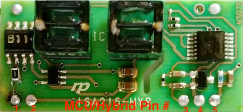
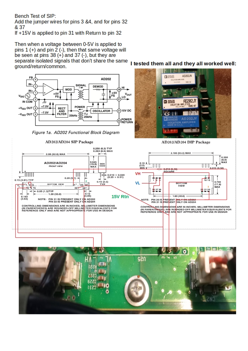
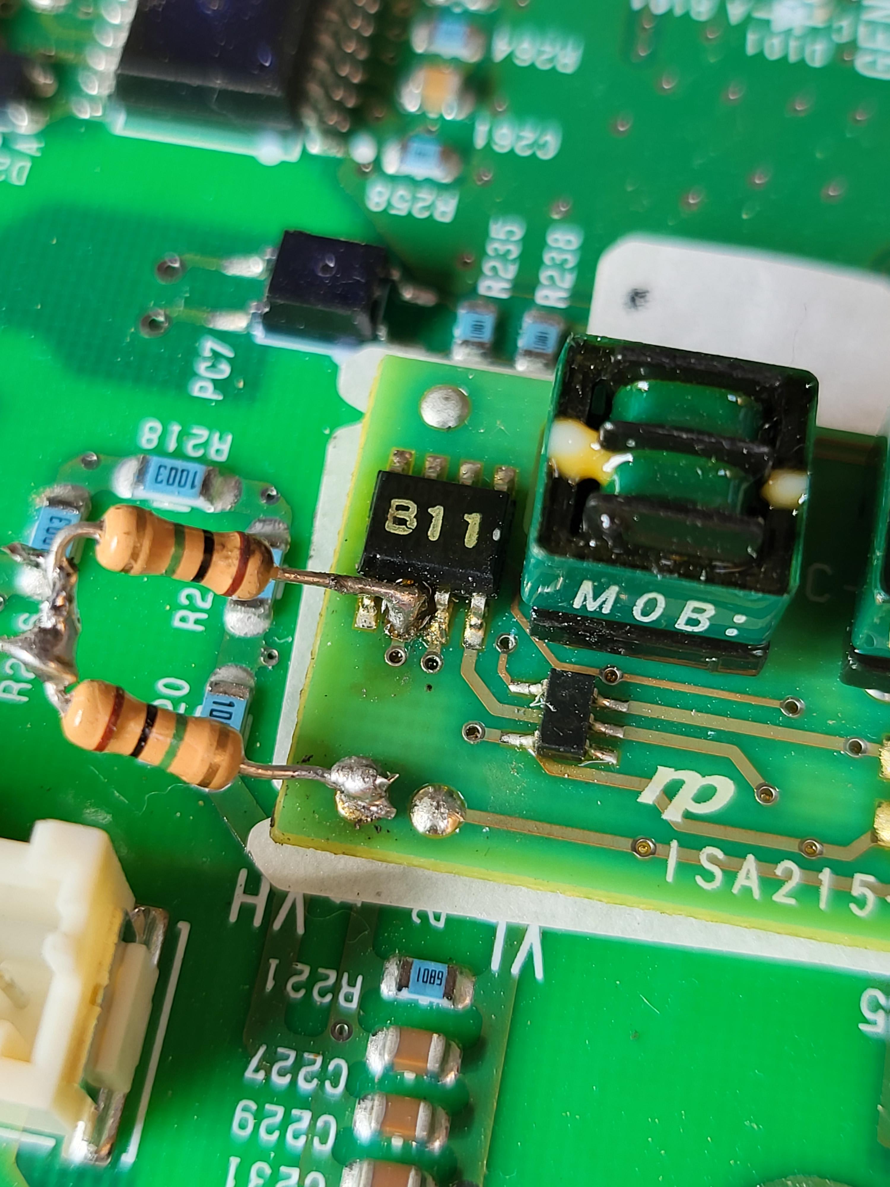
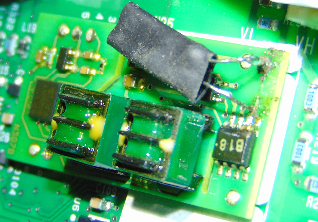
Ferst of all I deside not too use ad202. Desoldering small board I connect in "on branch" . As it's principal, it should translate voltage from Vin to vout as it is. Using oscilloscope I found it works correctly, output line was the same as input signal, but a little noicy. And in the same time, measering voltage with my appa105, I found mismatch, as all off you describe. Board working stable until Vpwr less than 9,5v. tl494 frec. I'd about 110khz. I change Ct down to 470p, and board start to translate a littel more to output, whan it get on it's input. Frec. is about 280khz. I find it as a good result.
Now, about some moments in pcb. 1 it's output with some noise. 2 the 2 power condensers on hv side. It's 1uf, but with the heating capasitence falls down to 300n!! 3 is possible problems in vias of the board.


