[ The P1A15 Troubleshooting Thread ] No READY. P1A15 error. Condenser charge timeout.

Mitsubishi i-MiEV Forum

Help Support Mitsubishi i-MiEV Forum:

This site may earn a commission from merchant affiliate links, including eBay, Amazon, and others.
i removed my hybrid from the control board and connected it up on the bench.

Used a 12V battery at 12.6 for the supply, measured 11.54 across the supply filter resistor so drawing 10.6 mA.

Used a regulated supply for the Input Signal, at 4.05 measured 4.11 at the Output pin 3.
Some other Input/Output voltages:
3,64 / 3.69
2.494 / 2.530

So my board has a bit of bias ~50mV above the Input voltage.

5V supplies measured +5.90 and -5.92
====[edit]
measured big cap at bottom corner while on the board: 753nF at 1kHz with smart tweezers. i would guess this would be a 1uF cap.
 
UPDATE

Thanks for getting back to me

I got fed up!!!!!!!!!!! so.......

Got the decade box out and connected it as someone had previously shown, In the end a 1.5m ohm resistor performed best throughout the voltage ranges so I fitted one and tested it over a period of a few hours and varied the voltage. It seemed to read ok so applied a bit of heat, this did vary the output slightly but decided to fit it all back together.

Hey presto, READY popped up. I refitted everything and drove it around the carpark at home, I have stopped and started it about 30-40 times and it has been OK.

Its not my favourite way to repair something but for a moment it will do until I can get another board to repair and test.

I will keep you posted and keep a close touch on the forum and hopefully help anyone else. The only upside is that I know the system back to front now!
 
That's great that you got a working car for now.

i'm not a fan of that "fix", considering the failed part seems not to be identified, but if it works then drive it.

Thanks for working to solve this problem, we just need to get a bad board or two to figure this out and what part needs to be changed.
 
We do need a spare board and I would prefer a proper fix.

I would love to get a new board made and then just fit the components but dont know how to go about it.

The most important thing from my point of view is that I now have a working car and this proves that the fault is with the hybrid board if the other faults have been exhausted, eg. AC, heater, charger etc.

It makes these cars worth fixing if it only takes a couple of hours and £10 of shopping! :D
 
Good news and bad news.....

I started it and stopped it loads of times today and it has gone into ready every time.

Drove her around and done ten miles, have to say it drove really good.

After coming back it didn't start.... P1A15 is back.

I checked the live data, battery voltage 353v, condenser charge 338v

I left it for 3 hours and she started, so this repair is only good if you can manage a long rest every time you stop!

I dont suppose we can identify all of the components on the board can we Kiev. Ill keep replacing them until I get to the end, i'm determined to get to the end
 
boothegermanshepherd said:
Is MC74HC the correct item for the 5 pin component?
No it is not, i think we had a discussion about that when looking up the part number for the "C5" marking code. The C5 version is obsolete and not available from the electronics parts vendors. The equivalent or better part is the "CA" marked part and i think i posted the link for it at RS Electronics. It is a Toshiba part number TC4S584F.

In some cases i will go back and edit my previous posts to add information or correct errors, to make it easier for the next guy reading thru all this stuff, and for me before i forget what i found...

PS: i'm glad you hammered on it until it threw the code again; it was a quick and dirty mod to get it working again, but shows that it is just a marginal fix.

My car had a random fail-to-start that progressively got worse. This was several years ago back before i knew about the DTCs, then i got a letter from Mits that my car had a recall to replace the MCU. It was a limited recall to certain build dates. Now i think it was a defect in the Hybrid and they knew which cars had them by the "Bnn." date code painted on the Op Amp.

i posted a list of all the ics on the board in the last week or so, but need to go back and edit to add the 5-pin part number which was unknown at that time.
 
Morning and thanks Kenny.

Here is my shopping list set to arrive tomorrow:

Standard Items Ordered Reference: 163596551
AD8677ARZ Analog Devices, Op Amp, 600kHz, 8-Pin SOIC
Stock no.:709-7326
Qty:3
Toshiba TC4S584F,LF(T Schmitt Trigger Inverter, 5-Pin SSOP
Stock no.:144-5204
Qty:30

I just wish I could get a new pcb or full board, I cannot understand why the manufactures dont make it any more, even if it was £100 I would buy one!

They do list a few others but again probably do not supply any more. I see that they call them isolation amplifiers, is there anything from another supplier that could be used / modified?

I will remove the board and try the new bits tomorrow, now im wishing that I put the board in on pins so I could just pull it off! :D
 
2012 vs 2015:
It depends whether or not it has the same harness and cable set and the fuse access cover, then it is likely the same inside. The revised MCU looks different inside and out.

i'll try to find some pictures.
 
Quick reply Kenny,

Good news anyway found a second hand one out of an accident damage vehicle to I would like to think its ok! Hopefully it will arrive in a couple of days.

The plan is to clone the new one and then check the voltages on the hybrid board before putting the board in the vehicle and hopefully having a runner, I will then check the live data to see actually how close the battery voltage is to condenser voltage.

Then I need to get to the bottom of the faulty one :roll:
 
With a 1.5 Mohm attached from the VH pin to pin 2 of the op amp has the effect of lowering the inverting input resistance to about 94kohms and increasing the gain from 1.0 to 1.07

With the board off you could remove the 1.5M and the 100k input on the bottom, then use the decade box to dial in the value needed to get an equal hybrid Output voltage, then solder a resistor of that value in place of the 100k.

[edit note]
The MCU control boards have an eeprom that codes the VIN to the serial number of the MCU.
 
I'm sorry to trouble you again Kenny, that sounds a good idea and I will try it, can you pin point which resistor is the 100k please?

Will this still give me the same symptom though, if I set it with the correct resistor in its place, what happens when the board is 70 degrees inside the mcu after driving? Will the output drop?????????
 
This won't solve the thermal issue but may give you more operating margin since you can raise the gain much more than ever possible from the addition of huge resistors to the top side.

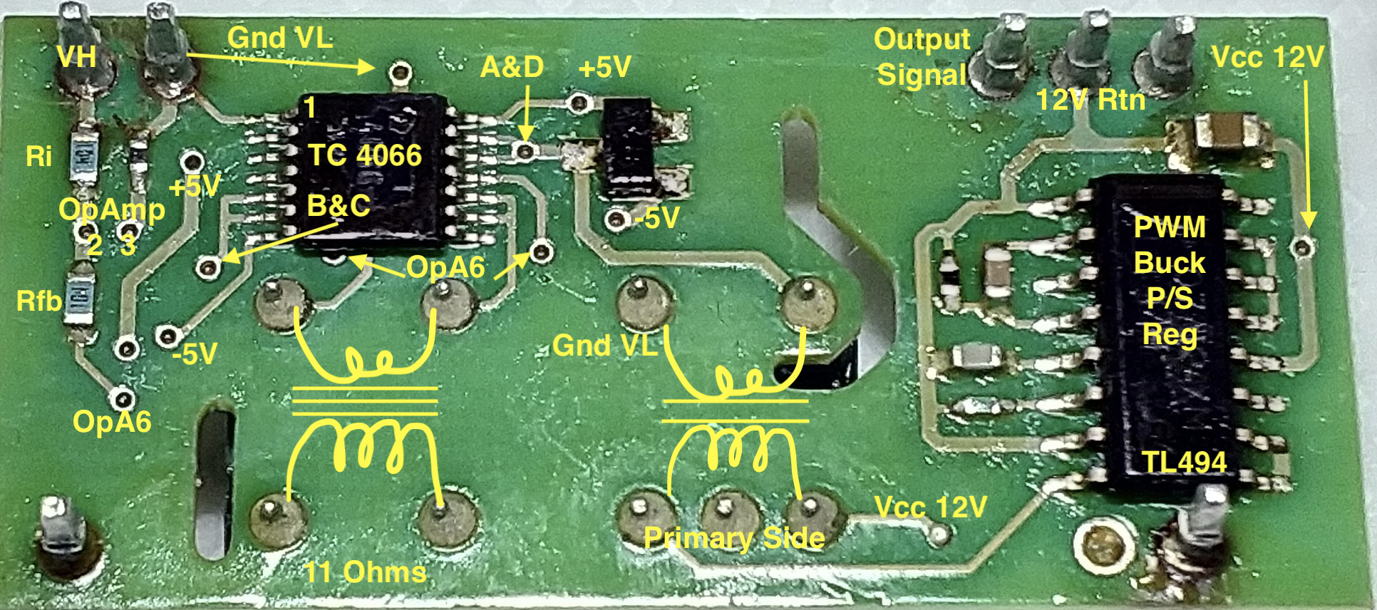
It is the blue resistor marked 104 and labelled Ri between the VH pin and the via marked Op Amp 2 in this picture. The gain of the inverting amplifier is set by the ratio of the the feedback resistor to the input resistor, -Rfb/Ri

3dJRlQy.png
 
To remove the hybrid, are you unsoldering the pins from the hybrid daughter board, or from the motherboard?
To make the hybrid "pluggable", do you know of any suitable pin-and-socket kits that provide, or could be cut into, single pins?

I need to upgrade my soldering equipment. Presently I have a Weller TCP1, 60W mains-driven, with magnetic temperature control, and a traditional aluminium-bodied manual solder sucker. Are you using a vacuum desoldering station? What would you recommend?
 
Hi Eddy,

I unsoldered the board from the motherboard and then refitted it the first time.

I am thinking of using some male and female pcb pins like these

https://www.amazon.co.uk/IZOKEE-Headers-Soldering-Connector-Prototype/dp/B07DBY753C/ref=sr_1_3?crid=1ADXQKC4EIZTU&dchild=1&keywords=pcb+pin+connectors&qid=1626292577&refinements=p_76%3A419158031&rnid=419157031&rps=1&sprefix=pcb+pin%2Caps%2C202&sr=8-3

Kenny is the man that will say if this is a good or bad idea!

I only use a weller soldering iron and a micky mouse hot air gun for removing components.

Plenty of flux and thin core expensive solder ;)
 
Amazingon tells me it can't find that item when i click the link...?

@Boo or Eddie, or anyone--can you read any marking codes on the 3-pin diode devices on

top

and bottom

hope to find the correct datasheet and the marking code is the best start.
 
Hi Kenny

I just tried the link and its ok? how odd

My board is back in for a moment, ill take it back out over the next couple of days as I have some more bits arriving and the second hand unit maybe here by then.

I will look when I get it back out, what is the best thing to use to clean the lacquer off of the board and components?
 
Back
Top