not charging my iON, cell or CMU or BMU problems

Mitsubishi i-MiEV Forum

Help Support Mitsubishi i-MiEV Forum:

This site may earn a commission from merchant affiliate links, including eBay, Amazon, and others.
martinwinlow said:
I appear today to have confirmed that the MUT3 can renumber CMU BMS PCBs
I actually thought that they would renumber themselves, using a daisy chained pair of wires between each CMU.

Are you sure you needed the MUT3 for this? Perhaps the MUT3 is needed to "kick things off", and the CMUs then renumber themselves based on their position in the daisy chain.
 
coulomb said:
martinwinlow said:
I appear today to have confirmed that the MUT3 can renumber CMU BMS PCBs
I actually thought that they would renumber themselves, using a daisy chained pair of wires between each CMU.

Are you sure you needed the MUT3 for this? Perhaps the MUT3 is needed to "kick things off", and the CMUs then renumber themselves based on their position in the daisy chain.
That's apparently exactly how it works, however the diagnostic tool is required to "kick it off" and cause the self renumbering to take place, as prior to doing that it was setting a fault code for the CMU and the battery gauge was empty. (Due to no cell voltages from a block of cells)
 
No 'kicking off'; there's a specific MUT3 app routine to do it (detailed on the SPeakEV thread, https://www.speakev.com/threads/i-m...u-ltc-chip-failure.144620/page-3#post-2829628).

Unfortunately, it does not appear to have helped 100% in my case as it appears the version of CMU PCB that I got is not entirely compatible with my very early i-MiEV (last 5 of the VIN is 00136 and V5 shows first registered 20Nov2009).

However, the car goes to 'Ready' and the wheels go around and around, albeit it is still on the car lift. It charges, too (from AC), but I have not had a chance to see if it is at the full 13A, let alone via DC (no facilities to do that here on the island anyway).

So, my next plan is to try to obtain a pair of the same version of CMU PCBs and try them in the car.

Anyone know where I could try?
 
It wasn't clear to me that there was a defective LTC chip, maybe so, but there were 2 very low cells, #38 and #42.

So after swapping out a CMU05 board, the low cell #38 is not reading low anymore? Was the cell voltage actually measured with a voltmeter to verify it's actual reading before and after the CMU?

As long as the pack is open, maybe some other tests might be to put the old CMU back in to see if the problem returns. And move cell #38 to another location. Change some things around and see what the tools show, etc.

i would definitely want to put a meter on CMU06 cells (cell #42) to get measurements.
 
Martin has probably forgotten to post back here but on SpeakEV he has reported the problem as solved.

There was an interesting wrinkle to the issue though - his car is so old that it has pre-production or very very early production CMU boards which are coloured Red instead of the normal Green and have an early revision number than nobody has ever seen before, and also a partially incompatible firmware!!

When he tried to fit a regular green coloured second hand replacement CMU, the re-numbering process worked, however there were other fault codes still set due to (we believe) incompatible firmware versions between CMU and BMU.

So in the end he had to have a new LTC chip fitted to the original red board, this has fixed his problem and the car is back on the road charging and driving without fault codes.
 
Sandrosan said:
Thanks Simon! Very good to know he has solved with a new LTC chip.
As long as it's done very carefully by someone with the right solder rework equipment and skills, it does seem that the LTC chip replacement is the most likely repair method to be successful, (side stepping all possible numbering and firmware issues) and the good news is the chip itself is still available to buy new at a very reasonable price, even if second hand CMU boards weren't available.
 
Greetings from Norway.
I have same problems with my BMU controller in Peugeot iOn. i have tried to resolder all possible points and it helped little bit. Before there was no connection with unit at all. Now its implausible : it can stay for some time and will fail after few minutes.
Where start to dig ?

I made some short video : https://www.youtube.com/watch?v=e28lBrikhdI&feature=youtu.be
 
Howdy Afi-g,

What mode is the car in when you were doing this video, e.g READY, ON, ACC, charging, OFF, etc.?

And you said that you touched up some solder junctions, but did you replace the LTC chip or any other chips?

If you desire to find the fault:
Do you have a hot air blower and/or some cold air in a spray can? You could try to induce or clear a fault by heating up sections of the CMU board around the LTC chip and the microcontroller, and also using cold-spray to cool off individual chips to see if the fault can be induced or cleared. This might reveal an intermittent solder connection, ceramic capacitor, resistor, etc.

To get the car back on the road:
It may be that you need to find a used CMU board and just swap it out rather than troubleshoot down to the chip level.

Simon or coulomb may know how to trigger a CMU renumbering without doing an eeprom swap.
 
Hi.
Will tell story from the beginning.
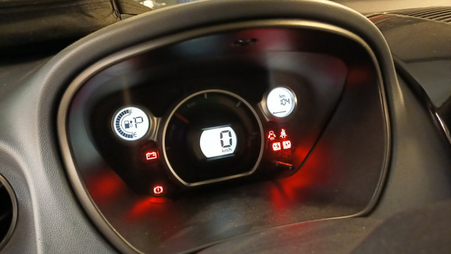
I bought this car with ``not charging`` problem. Fast charging was working, bet when you connect it to 10A charger, charger indicator turns on, fan starts, even cooling pump activates, but after few seconds everything stops and charge indicator on charging cable goes off. The yellow light in dash indicates fault. By the way, the car was running I took it home without any problem.
Since I do not have good diagnostic equipment , i use iCarsoft. Ther is no iOn or C-Zero so I use Mitsubishi iMiev as car definition. The following failures came :
Cell Voltage sensor BMU ( P1A33)
Remote CAN T/O/ Not equip ( U1113)
Charger state signal error BMU (P1A39)
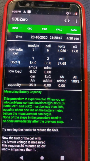
As well i use OBDLink MX and app OBD Zero to see whats going on cells itself.
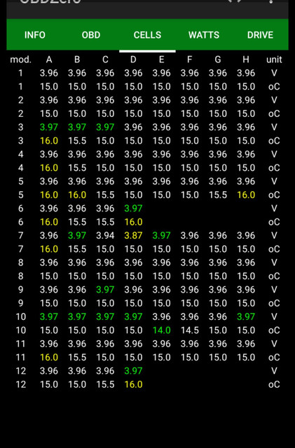
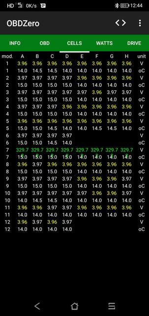
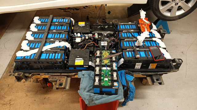
Row nr 7 in batt pack showed 329 V. Thats why i took down battery for closer check. What i found out that if you press gently with finger on processor in PCB for CMU ( this one which is located direct on battery) and you will disconnect and connect CMU again ( still with finger on processor or somewhere near by) the row nr 7 starts to answer and good values appear on screen. faults P1A33 and P1A39 disappears...
Fail U1113 is always active, but i believe, its caused that i use iMiev diagnostic soft for Peugeot. Might be i am not right.
I managed to get few CMU PCB, but they are in terrible condition - from flooded car...
I found one CMU with minimal water damage, cleaned it and replaced. Unfortunately it was with address for nr 3. So when two CMU boards with the same address was connected OBDLink showed failure for nr3. To check this CMU functionality I disconnected pack nr 3 . I was happy surprised that flooded CMU with nr3 was working like it shoud. CMU was replying and good values was showed on OBDLink MX. I put finger on temperature sensors, and they reacted: values changed on OBDZero app.
Thats why I decided to swap eprom from fault CMU with nr 7 to flooded with adress 3.
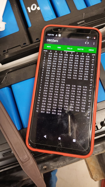
Now came the unexpended failure. After changing address CMU was recognized, but look like system freezes: all values for all batteries became the same. Its in attached picture .No green cells with highest voltage... I tried connect\disconnect this CMU for several times. It does not helpt. I cheked the car condition with OBD. More failures came to diagnostic( 6 or 7like temperature sensor, low voltage, mismatch and other) .
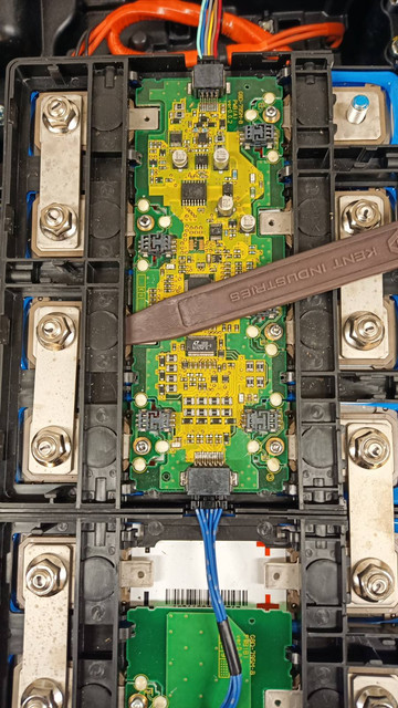
Then i took eprom back to defected CMU PCB. Result now is the same as before swap . With finger on ( actually i have a small plastic spade on side of PCM to make it banded little bit ) the failures gone ( except U1113 MiEV can T/o/ not equip).

All checks was done only with ignition on. I can`t turn ignition key to ready position, because the power cables is not attached to motor controller, as well pack nr 7 is not connected to the rest of the system.

Picture of freezed system with changed eprom should be there :


With banded PCB ( finger on processor) :


Failure on PCB :
 
Last update.

The system was standing during the night with defected PCB, but with the plastic shovel in corner.
There are no failure in the morning with ignition on. It indicates more than half battery,no warning lights.
Only failure on OBD as before U1113 MiEV can T/o/ not equip
As I posted before, i wont turn key to ready position, because its missing some wiring to the rest of the car..

Nearly bought all CMU boards from advertisement. They coming in Post tomorrow or on Monday.
If someone will need CMU boards in future, just let me know on PM

Some pictures attached :


That is a strange acting CMU. The pressure "fix" by pressing on the board makes me think that there is a "cold" solder joint that is acting intermittent, or a cracked ceramic capacitor. There is a conformal coating on the board that may be acting to hold a loose part against the solder pad

Ideas for repairs:
If you have the soldering tools and skills to touch up all the solder joints in the vicinity of the "pressing";

Use a tweezer measuring tool to check ceramic capacitors and resistor values.

Replace/swap the LTC chip with a known good chip.

Take it to a cell phone repair shop to do the soldering if you don't have the equipment, etc.

PS. Your display seems to show 8 cell temperatures, but there are only 6 sensors read by the microcontroller, what's up with that? The 8 cell voltages are read by the LTC chip.
 
Kiev, thanks for your reply.
No, i do not have tweezer measuring tool or hot air soldering equipment. But i will definitely buy everything. I do have soldering skills. I managed to swap address and after unexpected failure, I change it back to original CMU. It was like exam in university for me: a lot of worry and sweat .

As i posted before I purchased all CMU boards from iMiev. I found a guy which is tearing battery apart.

My idea is to find the right address CMU and just to plug. I hope it will work.

I will check all of CMU and will mark them with addresses for the future.
As well I will buy C LEXIA 3 to make complete diagnosis on the car and battery.
Will keep updated.
 
So.. The job is done.
I received all CMU boards and from third attempt i found Nr7.
Replaced battery, and Peugeot starts to charge.
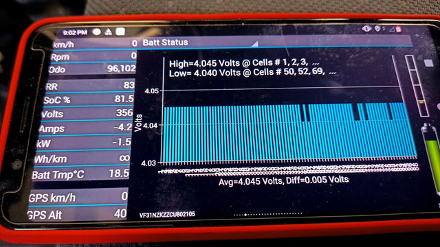
I been monitoring all charging process until the end on App caniOn150. Its look like that One batt cell in row 7 ( nr 52) is 0.010 mv lover then rest cells. Can it be reason why CMU was dead ( might be BMU tries to equalize it all the time and that's how CMU dies?) Do I need t worry abou it ?

How to find out what is rest SOH of whole battery pack ?


Afigeinnai said:
...
Its look like that One batt cell in row 7 ( nr 52) is 0.010 mv lover then rest cells. Can it be reason why CMU was dead ( might be BMU tries to equalize it all the time and that's how CMU dies?) Do I need t worry abou it ?

How to find out what is rest SOH of whole battery pack ?

Great work, it looks like you have a really good pack, not to worry about 10mV, that would not damage the CMU.

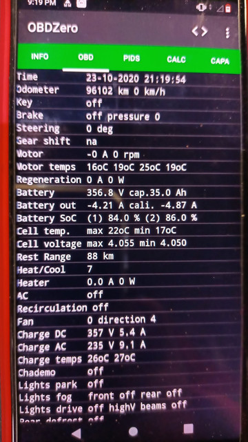
the pack has 35A-hr capacity according to your screens and all cells within 5 mV from this Canion screen. The Laef uses SOH but not the Mits.
 
kiev said:
Great work, it looks like you have a really good pack, not to worry about 10mV, that would not damage the CMU.

the pack has 35A-hr capacity according to your screens and all cells within 5 mV from this Canion screen. The Laef uses SOH but not the Mits.

So 35A-hr from 50A-hr its only 70%. I do not think that its very good result.
 
Afigeinnai said:
kiev said:
Great work, it looks like you have a really good pack, not to worry about 10mV, that would not damage the CMU.

the pack has 35A-hr capacity according to your screens and all cells within 5 mV from this Canion screen. The Laef uses SOH but not the Mits.

So 35A-hr from 50A-hr its only 70%. I do not think that its very good result.
While the cells might be 50Ah that is a full discharge from 4.2 volts to 3.0 volts.

The car only operates the cells between 4.1 volts and 3.6 volts, so the usable capacity when new is 45.8 Ah. 35Ah is therefore 76% SoH.

As to whether this is good or not, I don't think you've said the age or mileage of the battery pack ?

My Ion was at 39.9Ah at 6 1/2 years old and 28k miles but was down to 32Ah at 9 years and 55k miles. I replaced 4 cells which were well below the rest which increased it to 34Ah however it dropped to 32 Ah again over the next 5k miles, so was at about 32 Ah again when I sold it at 62k miles.

The cells on these cars just don't last very well I'm afraid. I think the reason is that the very small capacity means the cells are cycled a lot for a modest mileage (60k miles is nearly 1000 cycles) and the short range means it is common to have to deeply discharge the battery for "normal" driving which is very damaging for the cells.

If you want an EV that will do a higher mileage without as much degradation you need a much larger battery capacity so that the cycling is less and the discharges for normal driving distances are not as deep.

Edit: I see your screenshot shows 96,000 km or about 60k miles. So if you have 35Ah left at 60k miles you are doing a lot better than my car did...as even after some cell swaps it was 32Ah at 60k miles.
 
Thank you for very comprehensive reply.


Now i wonder to buy lexia3 diagnostic to do maintenance charging on traction battery. As far as i know maintenance charging should be done once per year.
I have some plans to maintain the car :
1.Change oi in gear box. ( i believe it`s standard oil ATF SP III ?)
2. Change the coolant from blue one to red\pink( originally it came with the blue)
3. Isolate PTC heater and houses. ( now its already cold in Norway)
4. To do some anti rust protection spray ... Its already rusted on chassis.
...........
5. To open cover for AC to check for moisture . I read that its a common problem that moisture gets in to Air condition unit, and when you found it , it`s too late. Will it help if I open it up and will seal with new silicone?
 
Hi, everybody. My Ion 2011 with 133.000 km. and 25Ah. has a problem with the cell 69. Like, high resistence. It´s very fast discarging and marks 2.6 v in max acceleration. With half charge i can see the turtle without great acceleration and 0.750mv difference between cells. When I charge always the 69 can´t be totally charged. And needs a lot of time trying and discarging other cells. The battery can´t be balanced correctly. Always with 16 bars.
In summer the problem is minor. (CMU reading better?) .

The problem is cell 69 o CMU 10. I think, generally in forums the problems are with 10 CMU or cells in this module. Curiosly always the same.

Well, I think to change the LTC in CMU 10 and the cell. Maybe the cell is ok. but I prefer the safe way.

The analog LTC 6802g-2 (2008) it was replaced (2011) (upgrade) for LTC6803g-2 .

https://www.analog.com/media/en/technical-documentation/data-sheets/680324fa.pdf

" It is pin compatible with the LTC6802-2, providing a drop-in upgrade."

LTC6802-2 Multicell Battery Stack Monitor with an Individually
Addressable Serial Interface
Functionally Equivalent to LTC6803-2/LTC6803-4. Pin Compatible with the
LTC6803-2

https://www.analog.com/en/products/ltc6802-2.html#product-overview
https://www.analog.com/en/products/ltc6803-2.html#

Analog recommends to use LTC6803-02. Maybe a long term, knows problems with LTC6802-02.

How you see to use the LTC6803-02. It's a big risk?.


I replaced the charger. Thank a you a this forum and I try to fix the battery.
 
Pepin,

From what you describe you have a faulty cell, not a faulty LTC chip.

If the voltage drops by much more than other cells when accelerating vs coasting the cell has high resistance.

Another way to confirm high resistance is to monitor the cell voltages while DC rapid charging the car from below 40% SoC - a cell with high resistance will go from being lower voltage than all other cells before you start charging, to within about a minute being higher voltage than all other cells - if you see this behaviour it's a clear sign of high cell resistance as the faulty cell cant take a high charge rate without going over voltage. This is how I diagnosed high resistance cells on my car.

So - lower voltage than other cells under acceleration and higher voltage than other cells during rapid charging is how to diagnose high cell resistance for certain.

I replaced 4 cells on my Ion last year, three of them not only had low capacity, but also exhibited signs of high internal resistance. This caused rapid charging speeds to be much slower and throttle much sooner because the faulty cells reached the maximum 4.105 volts long before other cells.


When I replaced the faulty cells rapid charging speeds returned to normal. Probably a coincidence but one of my faulty cells was 69....

You will be seeing the turtle at half charge when you accelerate because any individual cell going below 3.0 volts under load will immediately bring the turtle mode on until the voltage goes above 3 volts again. So it will go off again when you lift the accelerator and the voltage goes up again.
 
Back
Top