not charging my iON, cell or CMU or BMU problems

Mitsubishi i-MiEV Forum

Help Support Mitsubishi i-MiEV Forum:

This site may earn a commission from merchant affiliate links, including eBay, Amazon, and others.
Hi,

Thanks for the great info. I already ordered the CMU board from a reputable eBay seller, so I am not concerned about the board being another ID than 10, as he confirmed that. Rather I am a bit concerned that the board is not recognized because if was pulled from another VIN number... I guess I’ll find out...

About the diagram posted by Kiev, does it match in your experience ? So my faulty module (CMU 10 in diagbox and cells 71-74 in Canion) would be right under the passenger seat ?

I can put my car on stand no problem, but I have no clue how to support and lower the pack once unbolted :/
 
Gary12345 said:
Since it is likely you cannot see the failure (for me the chip looked fine but did not work properly) If you want to confirm that you have the correct battery module, just disconnect the little communications connector, then reconnect the battery pack multi plugs and check the battery voltages, the one that was jumping up and down will now have disappeared.

thanks.
Hi Gary,
There are 3 connectors between the car and the battery back (besides obviously the high voltage connection). Two at the front end and one at the back.

Are you saying only one is needed to switch the car on (without "ready") and read values with Canion ? In that case, which one is it ?

That is very interesting to avoid reassembling everything and finding out after the fact that the wrong board was swapped :lol:
 
tinoale said:
Are you saying only one is needed to switch the car on (without "ready") and read values with Canion ? In that case, which one is it ?

Hi,

It will not go to ready without the big orange cables connected but all you need is to run diagnostics to check if you have identified the correct CMU.

So in total it has these connections on the battery pack:
- 2 twin plugs at the front, these power the heater and air con
- 2 sets of high voltage cables
- 3 multi plugs half way down one side
- one little plug at the back, this is for power for the cooling fan on the back of the battery pack
- an earth connection, on the opposite side to the multi plugs

You need the multi plugs half way down one side (if you sit in the car, its to your left) plugged in then you can use something like an iCarSoft i909 to check if you have identified the right battery pack.

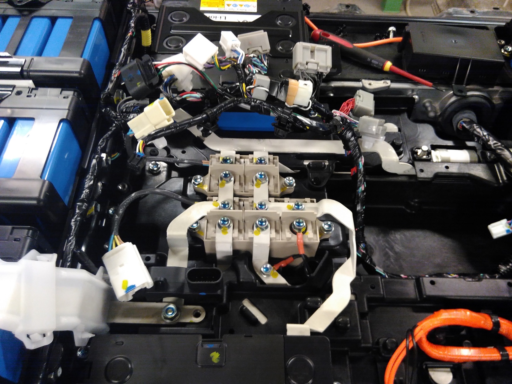
This is what I did - I was 99% sure which battery module was CMU10, but to confirm i took out the battery pack, disconnected the little communications connector on CMU10, then put the battery back under the car, raised it, plugged the multi plugs in and used the iCarsoft, it said CMU10 communications error - bingo you have confirmed which CMU is the faulty one.

It was not that expensive for the new voltage monitoring chip (£18) and fitting by a mobile phone repair guy (£25) but I didnt want to waste time and the money anyway so thats how i confirmed i had the right one.

Also, ***PLEASE READ AND FOLLOW THE SAFETY INSTRUCTIONS IN THE MITSUBISHI BATTERY PACK REMOVAL DOCUMENT*** Its not my fault if you put your fingers where you shouldnt or do something in the wrong order !

Thanks,

Gary.
 
tinoale said:
Hi,
About the diagram posted by Kiev, does it match in your experience ? So my faulty module (CMU 10 in diagbox and cells 71-74 in Canion) would be right under the passenger seat ?

I can put my car on stand no problem, but I have no clue how to support and lower the pack once unbolted :/

Well it depends where you have the steering wheel ! But CMU10 was as per the diagram, so if you sit in the car, it was front right but not the end one, one in from that one (if that makes sense).

I jacked the car up around 14 inches, supported it on concrete blocks, then i was able to get underneath. I used a pallet with trolley wheels on the ground, used 2 trolley jacks front and back, with 2"x4" wood, and jacked these onto the pack, undid the bolts, and lowered the 2 jacks so the pack came down onto the pallet.

I have some pictures but im not sure how to share them on here?

Thanks.
 
Hi Gary,

Superb info, thanks!

I have given some thoughts on how to remove the pack (with what I have at hands) and came up with the following sequence :
- put the battery in safe condition, remove 12v battery
- put the car on jack stands, remove the bottom plates, check for 0V, remove all the cables and all the bolts except the 6 big lateral bolts
- put 2 rolling boards (I ordered some that can take 400kg each) under the battery and add 2-3 layers of 2cm thick wooden boards to raise the level (the battery floor clearance is approx 15cm so rolling boards alone won't be enough)
- lower the car until the battery contacts the supporting boards (but still mainly supported by jack stands)
- unbolt the pack
- raise the car 1 jack stand position at a time, alternatively front and back, until the battery is entirely out of the car

Mouting would be the same, just reversed

Any comment welcome


I am aware of the risks, I'm an engineer and will take responsibility for whatever happens from my actions don't worry about that :)
I have the Mitsubishi dismantling manual (and some more).
I am just missing the main bolts tightening torque, have you found those ?

cheers
 
Hi,

Sounds reasonable - the battery pack is fairly tall so I ended up with blocks under the wheels - 12" high both sides, still the pack could not slide out, had to put another couple of inches under the wheels one side to get it out so you may need blocks to put the axle stands on, but see how it goes. Mine was on a pallet with wheels so there was probably 9" between the battery and the floor.

You also need a reasonable about of clearance to get yourself underneath the car to undo the covers where you test and remove the high voltage cables as they are fairly far under.

Some tips from experience - be careful when putting the battery pack back in that it is going up in the right place - you can squash cables if its not quite lined up and of course the bolts wont go in - much easier to move it around before they come together.

When you get the lid off the pack you still have 115v DC in front of you - the master fuse splits the pack in half but its still dangerous. So job 1 is remove some bus bars from the end of modules, then put the plastic cover back over so it cant contact. Once you do a few of these then its totally safe.

Last tip - do it in the daylight if at all possible - I did most of mine between 8pm and midnight as thats the only time I had, but can't really recommend it !!!

No idea on bolt torques, I did them up about the same as they came out !

Thanks.
 
tinoale said:
I have given some thoughts on how to remove the pack (with what I have at hands) and came up with the following sequence :
- put the battery in safe condition, remove 12v battery
- put the car on jack stands, remove the bottom plates, check for 0V, remove all the cables and all the bolts except the 6 big lateral bolts
- put 2 rolling boards (I ordered some that can take 400kg each) under the battery and add 2-3 layers of 2cm thick wooden boards to raise the level (the battery floor clearance is approx 15cm so rolling boards alone won't be enough)
- lower the car until the battery contacts the supporting boards (but still mainly supported by jack stands)
- unbolt the pack
- raise the car 1 jack stand position at a time, alternatively front and back, until the battery is entirely out of the car

Mouting would be the same, just reversed

Any comment welcome


I am aware of the risks, I'm an engineer and will take responsibility for whatever happens from my actions don't worry about that :)
I have the Mitsubishi dismantling manual (and some more).
I am just missing the main bolts tightening torque, have you found those ?

cheers
You might find the following thread about a CMU swap enlightening and very worth reading before embarking on your own swap:

https://www.speakev.com/threads/c-zero-battery-pack-repair.137750/

Lots of good information on the coding of the CMU boards as well as a novel physical approach to do the swap within a garage utilising threaded bars.

It looks like the CMU's are not VIN coded, however they are coded to their position in the pack. Rupert successfully dumped the eeprom contents of both old and new boards, and was originally planning to copy the old eeprom contents to the new board but was (so far) not successful overwriting the new eeprom, although we think we know why now. (The copying code was trying to write to the cells without first erasing them)

So instead he swapped the old eeprom onto the new board. The new CMU seems to be communicating and reporting voltages correctly however it claims that some cells are "undervoltage" and due to this the BMS will refuse to allow the pack to be charged. We think we've worked out why and have a solution but that is not test yet.

Hopefully we'll know in a few days if it's successful as it may be one of the first well documented CMU swaps of these cars. :)
 
coulomb said:
tinoale said:
The repair guy says that if we're going to swap the CMU_10 board we need to source a used CMU_10 board (not another number).
I've been reading the CMU firmware. It's hard going for me, but there is definitely a mechanism for "numbering" the CMUs. In fact, it seems to me that this happens automatically any time that there is a certain type of error (I can't be certain about what type of error, and it was some time ago I that I found this). But I have no idea how to trigger this process if needed. [ Edit: It's possible that the CMUs will detect say two CMU 5s and/or no CMU 10, and that this mismatch will automatically trigger the renumbering process. It has to originate from the BMU. ]
Automatic numbering like this seems unlikely - by what mechanism would they acquire consistent numbering when they left the factory ? If CMU_03 on my car is in a different location to your car how does that help with diagnostics ? :shock: There appear to be programming pads for the eeprom on the boards - much more likely that as the board is assembled on the production line a pin probe is attached to program the Canbus ID's.
So my conclusion is that you don't have to get a particular numbered CMU board, but I don't know how to make the renumbering happen. Perhaps there is a function on the MUT-3 that triggers it. Or some special CAN bus message.
Check the speakev thread I just linked to - Rupert was able to dump the contents of the eeprom which holds the Canbus numbering and while he wasn't able to overwrite it (yet) we think that's just because he forgot to erase the cells before writing them. :oops: Physically moving the old eeprom onto the new board is another approach though, which is what he has successfully done.
 
the cell numbering layout chart that Rupert used (referenced on the speakev forum) is incorrect. i posted a correct version on the previous page (p4) of this very thread:

http://myimiev.com/forum/viewtopic.php?f=23&t=3943&p=38824#p38832

the most negative, CMU01, is in the right rear corner of the pack, not at the service plug.
 
kiev said:
the cell numbering layout chart that Rupert used (referenced on the speakev forum) is incorrect. i posted a correct version here:
http://myimiev.com/forum/viewtopic.php?f=23&t=3943&p=38824#p38832

the most negative, CMU01, is in the right rear corner of the pack, not at the service plug.
Are you certain ? :?

Because if he had misidentified the modules then replacing the wrong CMU would not have fixed the problem with invalid voltages being reported...yet CMU_08 is now reporting valid voltages again after being replaced. That suggests to me that his layout is correct.

I agree that CMU_01 is most negative. The way we worked this out is to compare the bus bar routing in the pack with the location of the two 4 cell modules - according to Diagbox modules 6 and 12 are the 4 cell modules.

As this is an asymmetric configuration (one 4 cell module near the middle of the string and one at one end) there can be no doubt about which is the correct numbering direction - the end of the pack with a 4 cell module must be CMU_12. This connects to the positive output terminal therefore CMU_12 is the positive end and CMU_01 is the negative end.

So as far as I can see the diagram that Rupert and I derived is correct.

Can you explain how you derived your layout ? Your layout is inconsistent with the routing of the bus bars to the 4 cell modules.
 
Well, I have proceeded with the CMU10 board swap, and it worked flawlessly :D
I swapped a CMU10 board with another CMU10 board from eBay.

Nothing visibly wrong with the old board, no matter how close I look, could be the analog-digital converter as pointed out in this thread...

Car is good as new again :cool:

Thanks for all the excellent info provided here :ugeek:
 
DBMandrake said:
...
Can you explain how you derived your layout ? Your layout is inconsistent with the routing of the bus bars to the 4 cell modules.

It was several years ago that i worked this out using photos from dani's pack dissection, plus the initial incorrect cell identification made by Martin in his video when swapping out a bad cell. More recently i think this has been confirmed by correct identification and location of CMU10 by both tinoale and gary12345 in this thread.

Here is dani's photo of the main contactors showing the buss bar link for the (-) contactor going to the right rear corner module, and the buss bar link (+) contactor and pre-charge contactor going to the 4-cell module on the right side of the car.

XZocOHB.jpg


ref: former member Dani's thread, Wrecked i-MiEV Battery Pack Discussion, see page 2, post #19
http://www.myimiev.com/forum/viewtopic.php?f=23&t=3074&start=10#p27408
 
DBMandrake said:
...
Because if he had misidentified the modules then replacing the wrong CMU would not have fixed the problem with invalid voltages being reported...yet CMU_08 is now reporting valid voltages again after being replaced. That suggests to me that his layout is correct.

Of course i could be wrong about all this--there is so much that we don't know.

i don't know how to explain this, but i suspect that the CMU # is also stored somewhere else on the board, maybe in some memory register of the microcontroller chip.

Using my pack/CMU layout:
If he received a true CMU 08 board, but swapped his 02 board eprom onto the board for the swap, then the replacement board might be responding as if it were number 08 with the good cells that were in module 02. Canion might be able to show that the invalid voltages are still present, if it doesn't get confused by having two CMU 08 boards trying to respond.

Here's a test--try to read the CMU 02 cell voltages. [edit: using Canion if possible]
 
DBMandrake said:
kiev said:
Here is dani's photo of the main contactors showing the buss bar link for the (-) contactor going to the right rear corner module, and the buss bar link (+) contactor and pre-charge contactor going to the 4-cell module on the right side of the car.
Hmm, you've got me wondering now. If I was dealing with a dissembled pack first hand I could figure it out very quickly by tracing from the output of the pack backwards, but I still can't tell for sure one way or the other from piecing the various photographs together. :(

kiev said:
Of course i could be wrong about all this--there is so much that we don't know.

i don't know how to explain this, but i suspect that the CMU # is stored somewhere else on the board, maybe in the microcontroller chip.
Earlier in the Speak EV thread is a link to this German forum post:

https://www.goingelectric.de/forum/viewtopic.php?t=31166&start=60

If you translate it you'll see that BenJX claims to have read the EEPROM contents from his old board and written it to the new board to reprogram the Canbus ID. So until proven otherwise I think we can assume that the identifier is in this EEPROM.

I don't recall where I read it but I don't believe the version of the main microcontroller used has any EEPROM storage in it.
Using my pack/CMU layout:
If he received a true CMU 08 board, but swapped his 02 board eprom onto the board for the swap, then the replacement board might be responding as if it were number 08 with the good cells that were in module 02. Canion might be able to show that the invalid voltages are still present, if it doesn't get confused by having two CMU 08 boards trying to respond.

Here's a test--try to read the CMU 02 cell voltages.
As far as I know he received a CMU_08 board, however he swapped the EEPROM over from the old board. So there are a few possibilities:

1) If the CMU removed was really CMU_02 and the code is in the EEPROM the new board will now be reporting as CMU_02 and there will be no clash between board ID's, however the fault with CMU_08 would remain. Before disassembly CMU_08 was reporting completely invalid voltages (hundreds of volts per cell) but it is now reporting about 3.775 volts per cell. However it is also reporting that 7 of the 8 cells are "under voltage", which we can't explain at the moment.

2) If the CMU removed was CMU_02 and the code is not in the EEPROM, then we now have two CMU_08's in the car. This might explain why CMU_08 now gives voltage readings (from the wrong cells) however.... the BMS is only reporting faults on CMU_08 - and only under voltage faults. If CMU_02 was now "missing" due to duplicate CMU_08's, the BMS would be reporting a fault with CMU_02, but it isn't.

3) If the board removed was CMU_08 then we have the correct CMU_08 in the CMU_08 location and the voltage readings of the cells are real, however the "under voltage" reported in standard parameters measurement of CMU_08 which is setting a cell under voltage fault in the BMU is preventing the car from charging. But why is under voltage being reported simultaneously with all cells reporting around 3.775 volts ?

See the zipped diagnostic reports from post 48: https://www.speakev.com/threads/c-zero-battery-pack-repair.137750/page-3#post-2615428

(You'll need to translate the PDF's from French using something like https://www.onlinedoctranslator.com/ )

In global test 2 taken after the board swap and all faults cleared the BMU only has faults for CMU_08 set. Fault codes in the BMU are P1A7D "Failure of the voltage sensor cells of the controller of the traction battery 08" and P1A59 "Cell defect of the controller of the traction battery 08", "the default low voltage characterization". This despite CMU_08 reporting all cells around 3.775v.

So where does this leave us ? I'm getting really confused now...
 
It appears that Rupert printed out the lower 256 words of the eprom, but the datasheet indicates room for 512--i wonder what was in the upper block, if it were blank or had some data?

In his arduino code, ADW needs to be 9 instead of 8, in order to read out the upper block. Looking at the data, i think seems to show 4 rows of similar data (it repeat 4 times) in the lower block; i would guess there will be 4 rows of repeats in the upper. This may be a row of calibration data or upper/lower limits for parameters for each cell. i will post this over on the speakev forum.

i'll have to do some french and german translation to read the other threads and test reports.


edit, notes on DTCs:

P1A7D CMU08
The signal is received from the appropriate module CMU, which shows that one of the battery cell voltage has an invalid value.

P1A59 CMU08
The battery cell voltage is less than 2.3 V.

These are BMU trouble codes that the global test was reading as passed thru to the EV-ECU. There are 2 CAN busses, one from the EV-ECU to the OBDII connector that talks to the MUT, the other between the BMU and the CMUs. The MUT can access both, but voltages reported by the EV-ECU use a different set of CAN PIDs than those reported by the BMU. So it is not clear which CAN PIDs were used to read the 3.775 volts, versus the fault code showing less than 2.3 V.
 
kiev said:
It appears that Rupert printed out the lower 256 words of the eprom, but the datasheet indicates room for 512--i wonder what was in the upper block, if it were blank or had some data?

In his arduino code, ADW needs to be 9 instead of 8, in order to read out the upper block. Looking at the data, i think seems to show 4 rows of similar data (it repeat 4 times) in the lower block; i would guess there will be 4 rows of repeats in the upper. This may be a row of calibration data or upper/lower limits for parameters for each cell. i will post this over on the speakev forum.
Thanks for posting on speakev. :) As he has the pack out again at the moment now is the time to figure all these unknowns out and hopefully as well as get a successful repair, document and confirm some points that we're currently unsure about so that future people attempting similar repairs have solid info to work from.
i'll have to do some french and german translation to read the other threads and test reports.


edit, notes on DTCs:

P1A7D CMU08
The signal is received from the appropriate module CMU, which shows that one of the battery cell voltage has an invalid value.


P1A59 CMU08
The battery cell voltage is less than 2.3 V.

These are BMU trouble codes that the global test was reading as passed thru to the EV-ECU. There are 2 CAN busses, one from the EV-ECU to the OBDII connector that talks to the MUT, the other between the BMU and the CMUs. The MUT can access both, but voltages reported by the EV-ECU use a different set of CAN PIDs than those reported by the BMU. So it is not clear which CAN PIDs were used to read the 3.775 volts, versus the fault code showing less than 2.3 V.
The 3.775 volts is being retrieved directly from the CMU's I believe.

To access them you go into the specific CMU in Diagbox and then go to "standard parameters measurement" which is the normal way to retrieve live data from any ECU using Diagbox.

Standard parameters measurement in the BMU does not show all individual cells voltages but does report the minimum and maximum cell voltages as well as the number of cells which are at minimum or maximum voltage.

The CMU's also have a status section that includes whether the voltages are normal or abnormal low or abnormal high, and on the suspect CMU 7 of the 8 cells report abnormal low despite simultaneously reporting 3.775 volts +/- 5mV on the standard parameters measurement screen.

The CMU's do not seem to store fault codes as there is no option to read or erase fault codes in the CMU - the fault codes are all reported by the BMU which does have an option to read and erase fault codes.

I also have a Diagbox diagnostic tool for my Ion so I'm able to take measurements from my working car using Diagbox if it helps, and I've already compared Ruperts Diagnostic results to my own car. From what I can see although functionally equivalent in general, Diagbox and MUT-3 do not have identical feature sets and the user interfaces are very different. So not all features or measurements may translate from one to the other.
 
DBMandrake said:
coulomb said:
I've been reading the CMU firmware. ... In fact, it seems to me that this happens automatically any time that there is a certain type of error (I can't be certain about what type of error, and it was some time ago I that I found this).
Automatic numbering like this seems unlikely - by what mechanism would they acquire consistent numbering when they left the factory ?
If I'm right, they acquire their IDs, possibly every time they are reset, by their position in a daisy chain of special signals for that purpose:

zIoliju.png


I'll be the first to admit that the details on this drawing are staggeringly light. It's a study in minimality.

So there is this packet that is handled by Uart1 on the CMU processors, with 5 bytes; some sort of packet ID in the first byte, three special bytes, and a checksum of these three bytes in the last byte. Somehow, the number of zeroes in this packet determines the CMU ID. There is a table with an offset (0, 1, or 2 for the second, third, or fourth bytes respectively), and a mask that is one of 0x3, 0x0C, 0x30, or 0xC0. So pairs of adjacent bits are used; if the mask ANDed with the appropriate byte of the packet is zero, then this entry in the table determines the ID. My guess is that the CMU after "grabbing" an ID adds another pair of zeroes and sends it on to the next CMU. The third byte in the table (after the index and mask) is the CMU ID. I note that the entries in the table are ordered 7 8 9 10 11 12 1 2 3 4 5 6. So presumably the daisy chaining of this special CMU ID signal doesn't follow from most negative CMU to most positive, it starts in the middle with CMU 7.

If CMU_03 on my car is in a different location to your car how does that help with diagnostics ? :shock:
Sure, that's no good for anybody. But if I'm right, that will never happen. And copying of EEPROM contents should not be necessary, at least for the purposes of getting the CMU IDs correct.

I'm sorry to say that I haven't found any code yet that seems to be reading the EEPROM. There is a hardware device in the processor called the Clocked Serial Interface, which can handle the required 16-bit serial "characters". But it doesn't seem to talk to the EEPROM, at least at this stage.

There appear to be programming pads for the eeprom on the boards - much more likely that as the board is assembled on the production line a pin probe is attached to program the Canbus ID's.
Certainly, important data is written to the EEPROM when the CMUs are manufactured. My speculation is that calibration constants may live there.

Check the speakev thread I just linked to - Rupert was able to dump the contents of the eeprom which holds the Canbus numbering and while he wasn't able to overwrite it (yet) we think that's just because he forgot to erase the cells before writing them. :oops: Physically moving the old eeprom onto the new board is another approach though, which is what he has successfully done.
Fascinating stuff; thanks for the link. I'll be watching that SpeakEV thread.

I've seen a list of BMU connector signal names somewhere; perhaps from a hand written piece of paper, perhaps from @Kiev. If anyone can point me to it, I'd be most grateful.
 
Input and output pin configuration of BMU connector:

A is [1-26], and B is [1-22] 31-52 connector C-109

1 Auxiliary battery power source
2 EV-ECU control power source
3 BMU earth
6 CAN interface (high)
7 CAN interface (low)
8 K-LINE
12 Main battery cooling fan relay
13 Main battery cooling fan PWM signal
21 Input signal for main battery cooling fan speed

31 Applied voltage for main battery current sensor
32 Main battery current sensor (high)
33 Main battery current sensor (low)
35 Main battery earth leakage sensor
37 Local CAN (for main battery) interface (high)
38 Local CAN (for main battery) interface (low)
42 Main battery current sensor earth
43 Main battery current sensor earth(shielded)
46 Main battery earth leakage sensor pre-check signal
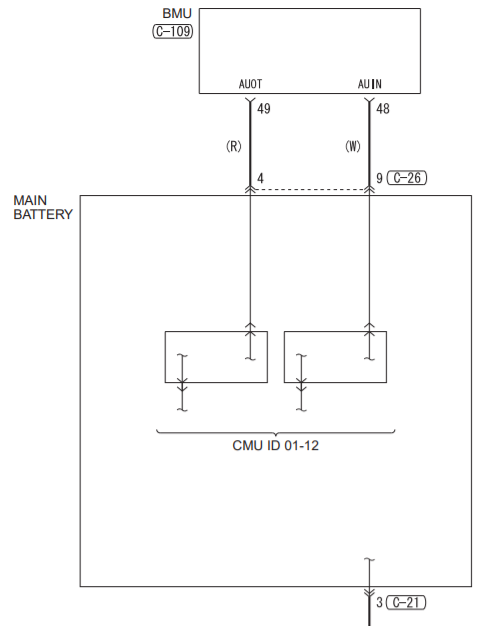
48 CMU ID automatic number input signal
49 CMU ID automatic number output signal

BMU "learning value"
If replacing the BMU, write the BMU learning value.

When the BMU learning value cannot be saved or when the battery for the auxiliary is removed for more than month, these procedures must be handled. Do not handle those for any other purposes.

1.Check the label attached to the main battery from the left rear wheel to check the manufacturing date.
note
Depending on the manufacturing date, the label may not be attached. If the label is not attached, check the production timing from the vehicle number to regard it as the manufacturing date of the main battery.
2.Calculate how many months elapsed from the next month of the manufacturing date of the main battery to this moment.
3.Connect the M.U.T.-III to the diagnosis connector with the electric motor switch in the "LOCK" (OFF) position.
4.Turn the electric motor switch to the ON position.
5.From the System select Screen of the M.U.T.-III, select the "BMU".
6.Select the "Special Function" from the BMU Screen.
7.Select the "Write learned value (change ECU)" from the Special Function Screen.
8.Select the "Manual writing" from the Write leraned value (change ECU) Screen.
9.Input the number of month calculated in the Step 2 to the "Sum total time back up (month)" from the Manual writing Screen. Write the BMU learning value.
 
Back
Top