No READY. P1A15 error. Condenser charge timeout.

Mitsubishi i-MiEV Forum

Help Support Mitsubishi i-MiEV Forum:

This site may earn a commission from merchant affiliate links, including eBay, Amazon, and others.
Yes that is right, pin 1 is toward and connects to VL.

Looking at the data sheets again this morning, there is a difference in the allowable supply voltage between the Toshiba version TC4066 and the TI version HC4066. [Hold for check: This may not matter for the device on the bottom side, but definitely would not work for the one on the upper side.]

Toshiba allows supply up to 18V; TI is limited to 6V Max.

[EDIT]
Wait, Need a circuit continuity check first. Does pin 7 (labelled as "Gnd") of the bottomside 4066 connect to VL or to the via labelled -5V ? If it is the -5V, then the HC won't work here.

aydmOQY.png
 
Good afternoon,

I have ordered hopefully the correct specifications from RS components, my shopping list is below


Toshiba TC4066BFT(N) Multiplexer Quad SPST 12 V, 15 V, 5 V, 9 V, 14-Pin TSSOP
Stock no.:663-4292
Qty:5
Texas Instruments TL494IDR, PWM Controller, 40 V, 300 kHz 16-Pin, SOIC
Stock no.:661-6875
Qty:5
ON Semiconductor MC74HC1G04DTT1G CMOS Inverter, 5-Pin TSOP
Stock no.:806-1460
Qty:100

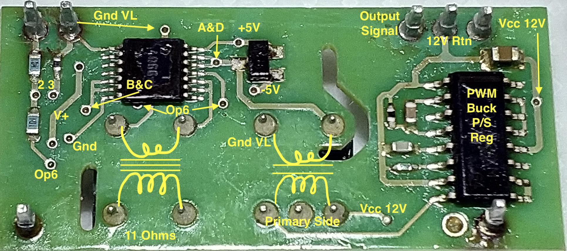
Is there any chance of telling me the capaciatance of the tow above pin 3, the return signal? Im sure the upper one is 10nf (103) but I may have miss measured the lower one and now lost it....... its either 10nf (103) or 100nf (104) ?????????????????

Thanks again
 
i measured mine on the board with smart tweezers, the upper one was 141nF and the lower one closest to pin 3 was 171nF. i think that creates a low pass filter ~3.4kHz on the Output. i don't know the switching frequency of the PWM, but expect that they would want to block it from getting thru.
 
Thats a bit strange then, my upper one off of the board was 10nf, could it have been faulty giving me that reading?

I have replaced the upper one now with 10nf and the lower one with 100nf, lets hope this doesnt bite me on the backside!

Do smart tweezers measure the component not the rest of the circuit without removing?
 
i doubt they are that smart, but they do seem to recognize the difference between resistors and capacitors. i would trust your off-the-board measurements more than mine, but they are close enough that it won't matter especially when caps are +/- 20% tolerance.

171 nF is almost .2uF, vs 100nF, so the filter rolloff is 5.7kHz instead of 3kHz--both are LPF.
 
Perfect, you are very wise in this field

I understand the main principles but am still learning about in depth electronics

So Kiev is yours all operational now or do you repair these units in your spare time?
 
That ECU programming probe stand was interesting, i never knew about the Background Debug Mode (BDM) adapters before. i wonder if any of the Renesas microcontrollers used in all the iMiev ECUs have DBM capability, and if so, if we could use something like that to read some firmware hexcode. i reversed the 8051 MCS51 code of the Bosch Motronics back in the '80s, and worked with members coulomb and piev on reversing the TCCH chargers (also MCS51 code) over on the diy electric car forum using an ICP backdoor. Being in Australia coulomb knows how to throw a Boomerang.

Mostly just helping folks out to repair units, i have an obstinate OBC from Sebastian that i am working on.
 
Im sure that they should, have you got any chip codes and I can look

I was thinking if I sort my problem getting a second hand unit to repair and virginising it so that I can test it on my vehicle and also then fit it to another
 
i'll have to find some part numbers; coulomb has looked at these also and knows more about the processor model numbers.

What i'm keen to figure out is what is the failure mode of the 4066 (assuming that is the culprit) that has affected so many owners. The Toshiba datasheet indicates the ON-state resistance of a switch is about 120 nominal to 250 Ohms max. at 25C with a 10V Vcc. If pin 7 that i called Gnd is at -5V, then i expect this to be valid Ron. If pin 7 is at VL, then Vcc is only 5V and the resistance goes up to 290 nom to 950 Ohms max at 25C.

But Toshiba doesn't show the internal details of the device such as TI does for their HC4066 device, which has a lower Ron of 30 to 50 Ohms, but only allows 6V Vcc. Looking at the inside details we can see that the source of the switch resistance is in the ON state resistance of the internal FETs.

So i suppose that the temperature sensitivity that is causing this fault is possibly a degraded FET, or that the low voltage supply and control signal to this device is somehow getting pulled lower than the design point. That brings me back to the two capacitors on the top side that are holding up the +5V and -5V supplies with respect to VL. My tweezer measurement on the board reads these as 5pF, which seems really low for a supply decoupling capacitor?

A counterpoint to the cap theory is that those +/- 5V supplies are also used in the OpAmp too, so it would seem that they must be okay for the op amp to be working properly. And the localized heating near the 4066 chip was directly and nearly instantly causing the Hybrid Output voltage to drop.

pTWMgtq.png
 
At my end nothing more can be done, but just to note since this morning I left the voltages connected for the day and the output recovered to 3.90, still short of 4.0

I just need to wait for the postman...............
 
Would you be able to measure the voltage at the via coming off of pin 7 that i labelled as "Gnd" with respect to VL? i suspect it might be -5V rather than 0.
 
That is good, i had made an assumption of the drawing that pin 7 was Gnd because that was in the datasheet, so this is good to get that corrected.

If you had time to measure the via marked "+5V" with respect to VL--that would show if the low voltage supplies were symmetrical.

i had assumed that the 12V gets switched thru the power transformer Primary winding and created a 12V AC on the secondary, i.e. +/-6V pk-pk. This gets rectified by the 3-pin diode on the bottom to create approximately +/- 5V supplies (it is a little more since the diode drop is less than 1 volt, more like 0.359 according to your measurement, likely Schottky diodes).
 
i've thought about. The transformer windings might need some research, but almost all the components are known.

They must not have been too worried about space--look at the huge size of that black 275 Ohm resistor on the Low Pass Filter at the Output pin 3 on the upper layer. Couldn't they have made it any smaller? :lol:

thanks for the voltage measurements, the +5 supply is somewhat lower than the -5, but i don't know if that could be related to the fault or not. On my board i measured the diode drop as 0.565 for the + and 0.571 for the - side.
 
Back
Top