Main Traction Battery Upgrade i-MiEV

Mitsubishi i-MiEV Forum

Help Support Mitsubishi i-MiEV Forum:

This site may earn a commission from merchant affiliate links, including eBay, Amazon, and others.
Possibly, I can see the messages on my OBD snooper. I haven't checked the rate yet. Not sure what you mean bi directional. It passes messages from the EV ECU to the BMU and from the BMU to the EV ECU if that is what you mean.

I measured the resistance going to the EV ECU and to the BMU. It matched the drawings I saw.

The BMU has high impedance in the k-ohm range. The EV ECU has around 200 ohms. So I did not terminate the end going to EV ECU but I did terminate the end going to the BMU.

It matches their drawings where the terminator is in the CMU and on the Vehicle on the ETACS ECU.
 
Just for grins, what are the pins?

ECU connector and pins:

BMU connector and pins:

I only disconnected the wires from BMU pin 6 H and 7 L. Took those to the output of the bridge.
Connected the input to the bridge to the BMU pins 6 and 7.

So, BMU -- Bridge -- ECU

Same code I posted before just without any bit modifications. Shouldn't be causing delays by just passing. I suppose I could choose to be interrupt driven to not miss things. Possible it's too slow.
 
Yes, first to admit I’m no expert but looking at the code you posted I gather that it reads data on Can1 and sends it to Can0, then reads Can1 but the corresponding send to Can0 is missing??
Well, good catch. I’ll have to look at it when I get home. Maybe I truncated it somehow by accident. It was supposed to be sending both ways. Rookie mistake. Thanks

Looks like that’s just a typo on the forum. It looks right in my code.
 
Last edited:
Maybe have to set some filters for just the PIDS for the BMU. The full buss traffic may overwhelm the bridge? except you wouldn't expect too much just during charging...so that is puzzling
 
Maybe have to set some filters for just the PIDS for the BMU. The full buss traffic may overwhelm the bridge? except you wouldn't expect too much just during charging...so that is puzzling
I was thinking along the same line.... maybe I'm not getting some command from the ECU to the BMU like extended packets or something and it is expecting a response.

The reason I say that is because the MUT3 won't talk to the BMS at all with my bridge in place it says there is no BMS!

Update: Ran a test with bridge in place. I snooped the bus while running the MUT3. Clicked on the button for EV ECU and the MUT sent
0x751 02 1A 90 00 00 00 00 00
ECU response
0x752 10 13 5A 90 4A 41 33 32
0x752 30 00 00 00 00 00 00 00
The spits out what looks like the ECU part number

When I click on BMU the MUT sends
0x761 02 1A 93 00 00 00 00 00
But no response.

I must be too slow or I’m filtering some messages.

Ok I fixed it! Maybe this is what you were trying to tell me.

I didn’t turn on the code to listen to CAN1
CAN1.watch.For();
 
Last edited:
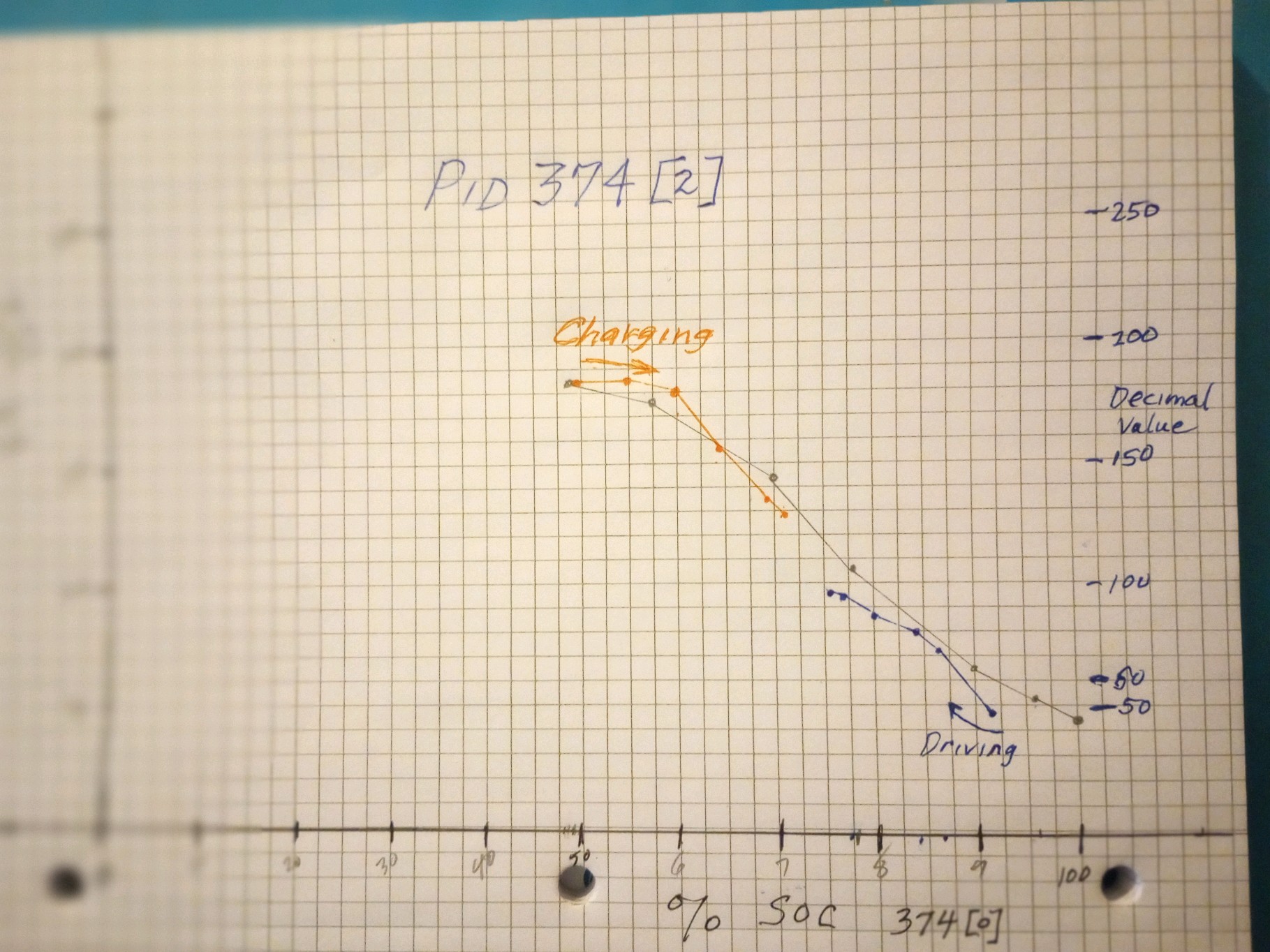
BMU PID 374 [2], the third data byte. The first 2 bytes are the SOC1 and SOC2 that David discovered, but what does the third byte report?

Orange is from a charging session, Blue is from a 2023 driving session, Pencil line is a recent 2024 driving data set. These are the decimal values of the pid plotted versus SOC1 %

8wLKv4K.jpg
 
No idea but do you think this value is required to get the SOC ‘spoofing’ working correctly? Are we positive that the BMU is using PID 374 do set the tortoise @ 10% SOC, start power reduction or shut down the car?
 
I played around with modifications. When I modified 374 byte 6, the estimated range value on the dash changed. Note that byte 6 is static. It never changes and OBDZero says it’s the capacity of the battery as reported by the BMU. So I multiply byte 6 and send it to the ECU. My range went to 131 miles. I changed nothing else. The car went to ready and I drove 7 miles, then I got the dreaded car ! Error. Still drove normally, so I came home. The MUT reported can bus errors indicating it lost communication with the BMS and meter. Seems like the ECU is looking at these other values in PiDs 373 and 374 for vehicle health. Now, to play around and see what the others affect.

I’m adding SoC calculations based on 90Ah and then I’ll take another drive.
If I understand you correctly byte 6 is the max battery capacity @100% SOC (roughly 45Ah with a new battery) did you multiply this value by 2 and send it to the ECU (which has a 60Ah limit)?

We do know that the BMU constantly uses Coulomb counting to update SOC therefore them relevant PIDs also need to be corrected.
 
If I understand you correctly byte 6 is the max battery capacity @100% SOC (roughly 45Ah with a new battery) did you multiply this value by 2 and send it to the ECU (which has a 60Ah limit)?
No byte 6 isn't constant. It is one of two numbers on the network that give the present battery capacity. The other is PID 762 byte 0 = 36 bytes 3 and 4. 374 Byte 6 has a resolution of 0.5 Ah while PID 762 has a resolution of 0.1 Ah. piev changed the RR when he changed the value of 374 Byte 6 so we know that 374 byte 6 is the capacity used to compute the RR. In my experience 374 byte 6 varies more than 762 capacity.

Which of these if either is the true capacity is a good question. In any event knowing the capacity more precisely than +-0.5 Ah is a challenge.
 
Last edited:
No byte 6 isn't constant. It is one of two numbers on the network that give the present battery capacity. The other is PID 762 byte 0 = 36 bytes 3 and 4. 374 Byte 6 has a resolution of 0.5 Ah while PID 762 has a resolution of 0.1 Ah. piev changed the RR when he changed the value of 374 Byte 6 so we know that 374 byte 6 is the capacity used to compute the RR. In my experience 374 byte 6 varies more than 762 capacity.

Which of these if either is the true capacity is a good question. In any event knowing the capacity more precisely than +-0.5 Ah is a challenge.
Sorry, you are correct but it doesn't change often. in my case it shouldn't matter for experimentation since I'm just multiplying it by 2. Based on my experiments the ECU is calculating Rest Range based on [0] and [6]. [1] seems to drive the display if my memory is correct.

I wrote some quick code to test my theories. Those are the only 3 bytes I changed and the car drove no issues. My SoC calculations need some more work but I'm almost there I believe.
 
Ok, update.

I wrote some code to calculate my own SOC. I was able to drive over 100 miles. My algorithm was not too good so it said I was empty around 3.5 volts. So, that means I should be able to go a good bit more before empty.

It is funny how simple their software is..... All you need to do is monitor voltage and current on 0x373 and compute SOC then write it back out on 0x374 [0] and [1]. I also change the Capacity value in 374 [6] to 90 Ah. if you want to get fancy you could degrade this value based on time and cycles but I don't think you need to.... if you keep up with voltage you should never get in trouble. Only thing I can see [6] doing is changing the GOM range value. So, currently it jumps around some but the car doesn't seem to use it for control it's just a feel good for the driver. The control seems to be based on [0}. When it gets to 0.2 % SOC the car stops working no matter what your voltage is...... I got this estimator from OBDZero: He also uses amp hrs and this is correction factor. he may be using individual cell voltage but the concept is the same. I haven't figured out the turtle yet.

if (v < 268.73) { v = 0;return;}
if (v < 312.32) { v = 22return;;}
if (v < 321.62) { v = 35;return;}
if (v < 326.01) { v = 47;return;}
if (v < 332.09) { v = 66;return;}
if (v < 332.43) { v = 85;return;}
if (v < 333.11) { v = 97;return;}
if (v < 333.95) { v = 110;return;}
if (v < 335.47) { v = 122;return;}
if (v < 340.20) { v = 135;return;}
if (v < 344.59) { v = 147;return;}
if (v < 347.8) { v = 160;return;}
if (v < 351.35) { v = 172;return;}
if (v < 355.58) { v = 185;return;}
if (v < 360.14) { v = 197;return;}
if (v < 365.04) { v = 210;return;}
if (v < 369.94) { v = 235;return;}
 
Ok, update.

I wrote some code to calculate my own SOC. I was able to drive over 100 miles. My algorithm was not too good so it said I was empty around 3.5 volts. So, that means I should be able to go a good bit more before empty.

I haven't figured out the turtle yet.
Great progress

Depending on what charge/discharge curve you’re looking at, @3.5V your NMC cell capacity is down to 5-10% and voltage will drop fast afterwards.

With the original

What we know so far the tortoise lights around 10%, power reduces around 1% and the car stops moving close 0% SOC, question is what PID is used to monitor these stages.
 
piev said:
I wrote some code to calculate my own SOC. I was able to drive over 100 miles. My algorithm was not too good so it said I was empty around 3.5 volts. So, that means I should be able to go a good bit more before empty.

Computing the SoC from the voltage is quick and easy solution and it is a step in the right direction. But it doesn't work well unless the amps are between -1 and 1 for at least some minutes. When the battery is under load the SoC computed from the voltage can be as much as 20 % points below the true SoC.

When the battery is under load or charging a more accurate SoC can be found by keeping an account of the Ah in the battery using coulomb counting. The SoC is then equal to 100 * remaining Ah / capacity Ah.

I'm almost certain the the car's power down function is based on low cell voltage not SoC. In some of the data piev has sent the car is still running at full power even though SoC1 and SoC2 are zero. They are zero because they are based on the reset capacity of 45 Ah when the true capacity is 90 Ah. The BMU's Ah account is 0 because more than 45Ah have been used. However the cell voltages are still well above the power down voltage.
 
I'm almost certain the the car's power down function is based on low cell voltage not SoC. In some of the data piev has sent the car is still running at full power even though SoC1 and SoC2 are zero. They are zero because they are based on the reset capacity of 45 Ah when the true capacity is 90 Ah. The BMU's Ah account is 0 because more than 45Ah have been used.
Not convinced as some reported that they could turn on the tortoise or even shut down the car just by changing SOC? One early tester also mentioned that he was able to almost completely empty the cells (2.8V) without any sign of tortoise or power loss when he artificially increased the battery capacity and kept driving?

Maybe the difference in behaviour is due to BMU/ECU FW changes?

Integrating the battery current over time (Coulomb counting) seems definitely a more accurate way to keep track of usage and charge/regen.

Maybe a bit premature but any thoughts on how best to deal with capacity changes due to low/high cell temperatures?
 
Computing the SoC from the voltage is quick and easy solution and it is a step in the right direction. But it doesn't work well unless the amps are between -1 and 1 for at least some minutes. When the battery is under load the SoC computed from the voltage can be as much as 20 % points below the true SoC.

When the battery is under load or charging a more accurate SoC can be found by keeping an account of the Ah in the battery using coulomb counting. The SoC is then equal to 100 * remaining Ah / capacity Ah.

I'm almost certain the the car's power down function is based on low cell voltage not SoC. In some of the data piev has sent the car is still running at full power even though SoC1 and SoC2 are zero. They are zero because they are based on the reset capacity of 45 Ah when the true capacity is 90 Ah. The BMU's Ah account is 0 because more than 45Ah have been used. However the cell voltages are still well above the power down voltage.
Yes, I believe you are correct. I am not finished characterizing the behavior. Yesterday, driving home the vehicle suddenly stopped. I sent you the data. Not sure why yet, I got no turtle I just lost all power and ready went off. it wouldn't start back up either. I plugged in my laptop and changed the SoC and it went to ready and I drove home. Still no turtle. So, I believe the turtles come on from low cell voltage. I haven't drained the battery enough for that to happen so I may just play with changing some cell voltages with the bridge to see what happens.
 
I think meddling with the SOC has disabled the tortoise function somehow:

According to your own posts earlier on (#18 & #20) this still worked (others reported similar behaviour), only difference you ran NMC90 cells with the original BMU.
 
piev said:
I plugged in my laptop and changed the SoC and it went to ready and I drove home.

Very interesting! I may have to agree with Mickey that it's SoC and not voltage but lets see.

I think that a coulomb count should be added to your program.

This requires a storage variable remAh containing the remaining Ah in the battery and a calculation of the Ah added or used each time the BMU sends a new value for the current. Once this is computed we can compute a new value for the SoC which can be sent on through the network. This value for the SoC is needed as well as the SoC based on the voltage that you has already calculated. I will suggest how to shift from the one SoC to the other later.

PID 373 contains the amps. This value doesn't need to be changed in the bridge. To compute the remAh we compute the amps and the time between the previous PID 373 and the new PID 373. Intr means the integer value.

amps = (intr[2] * 256 + intr[3] - 32700) / 100.0;
remAh = remAh + amps * step;

amps is positive while charging and negative while discharging. So the remAh will increase while charging and decrease while discharging.
step is the time between PID 373s in hours. If the time difference between PID 373s is precisely the same each time then step can be a constant. If not then it must be computed each time. This can be done with this code:

presentTime = currentTimeMillis()
step = (presentTime - previousTime) / 1000 / 3600;
previousTime = presentTime;

And the SoC is

SoC = 100 * remAh / capacityAh;

capacityAh = PID 374 intr[6] / 2.0;

Note that this calculation requires 4 storage variables, capacityAh, remAh, presentTime, previousTime.
 
Back
Top