kiev said:
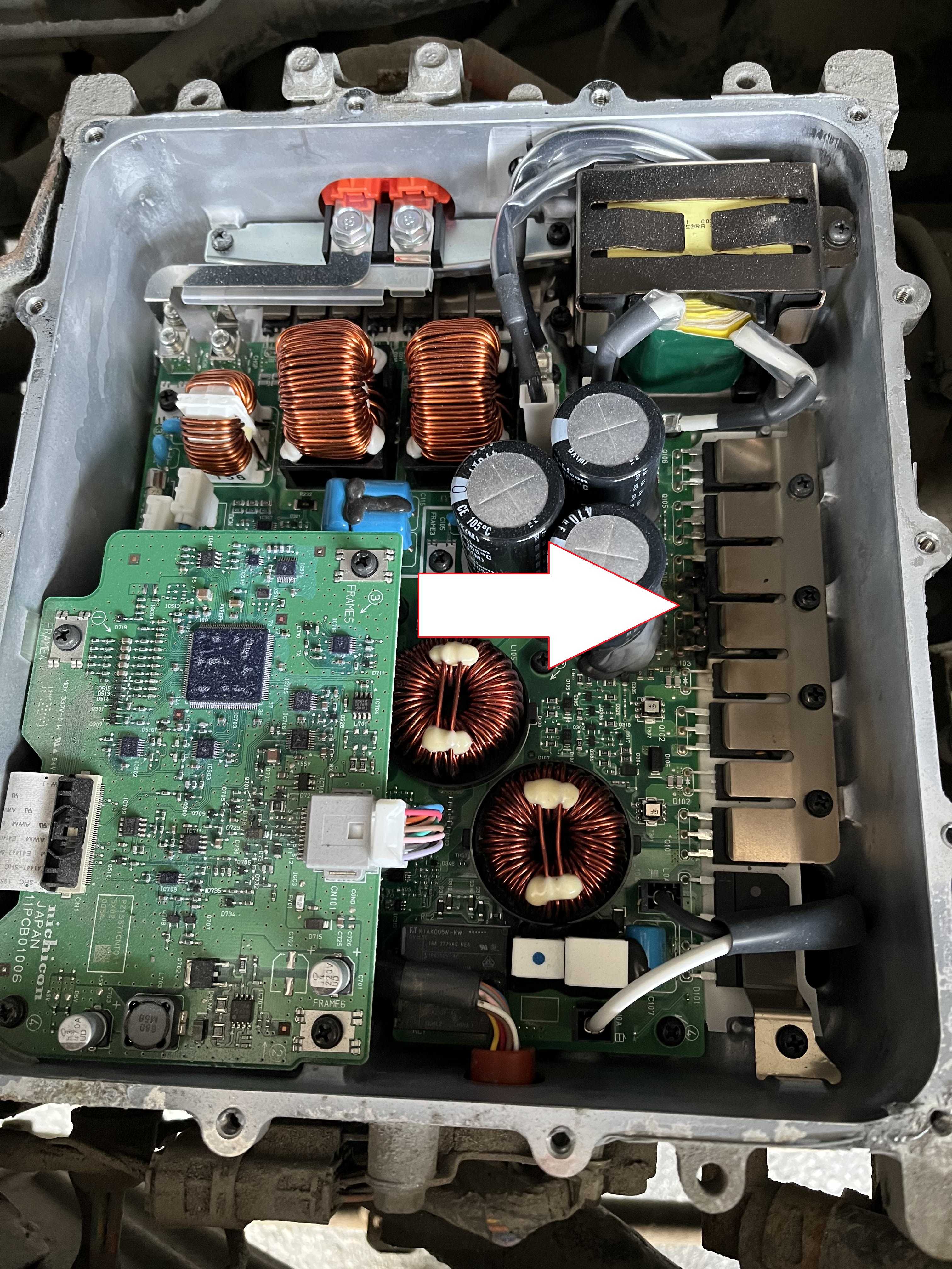
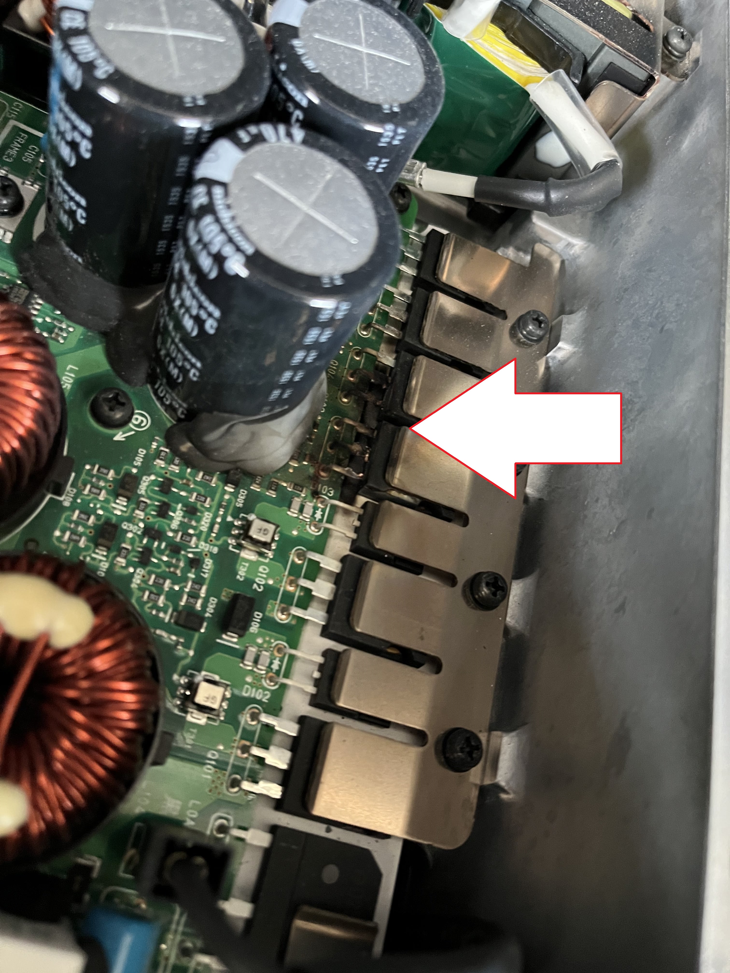
i think if you were to proactively replace the 20A MCU fuse as a maintenance item, then your old OBC would work just fine for a good long time.
i'm still doing research on the failure modes. i'm struggling to understand how the MCU fuse could experience an over-current condition and blow, without taking out the little 20A fuses on the input of the DCDC or the output of the OBC.
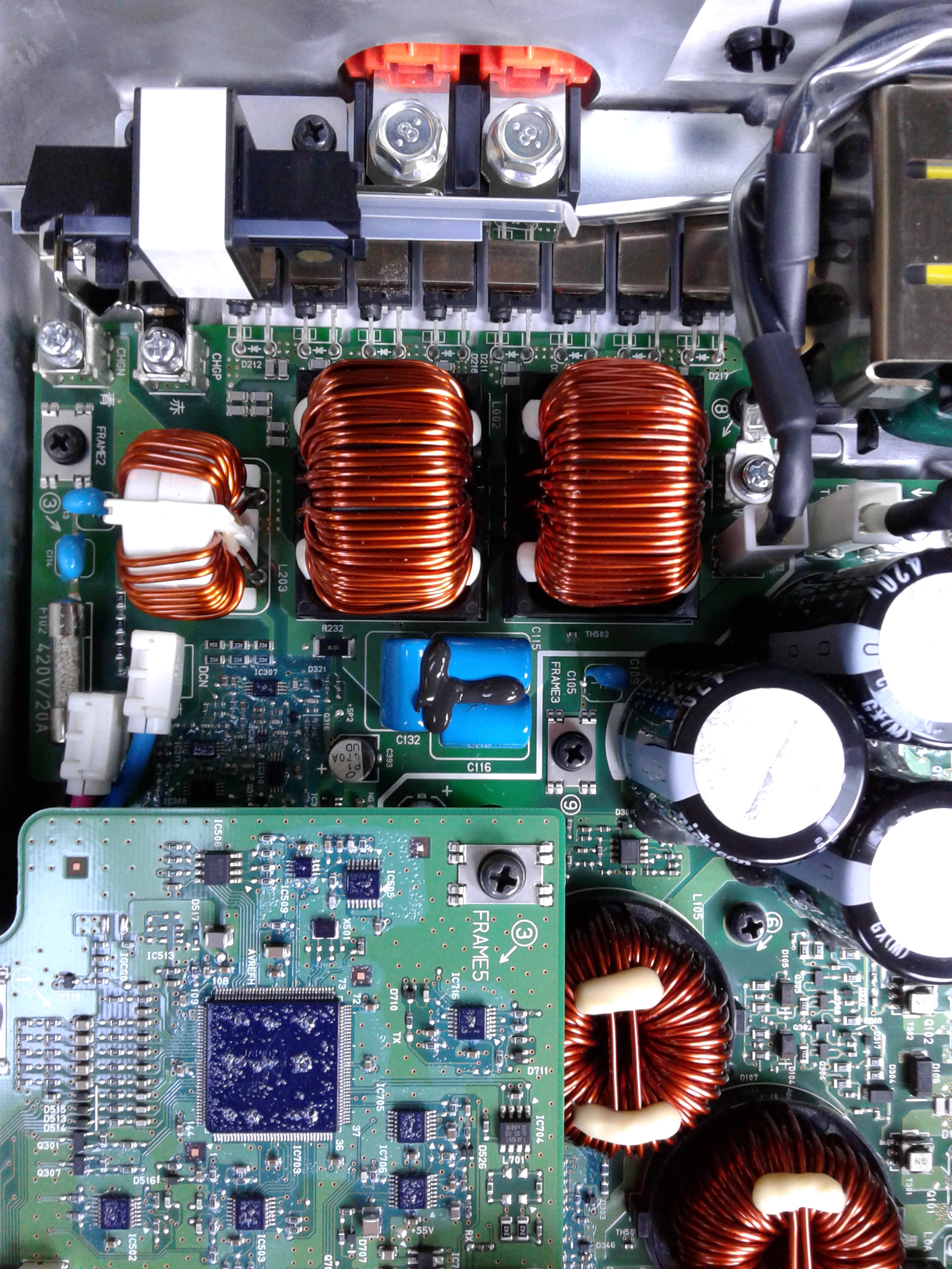
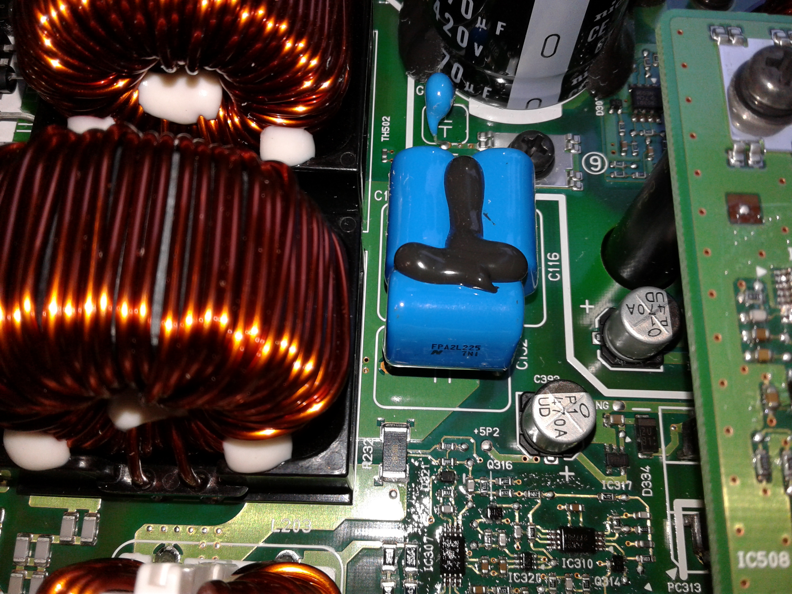
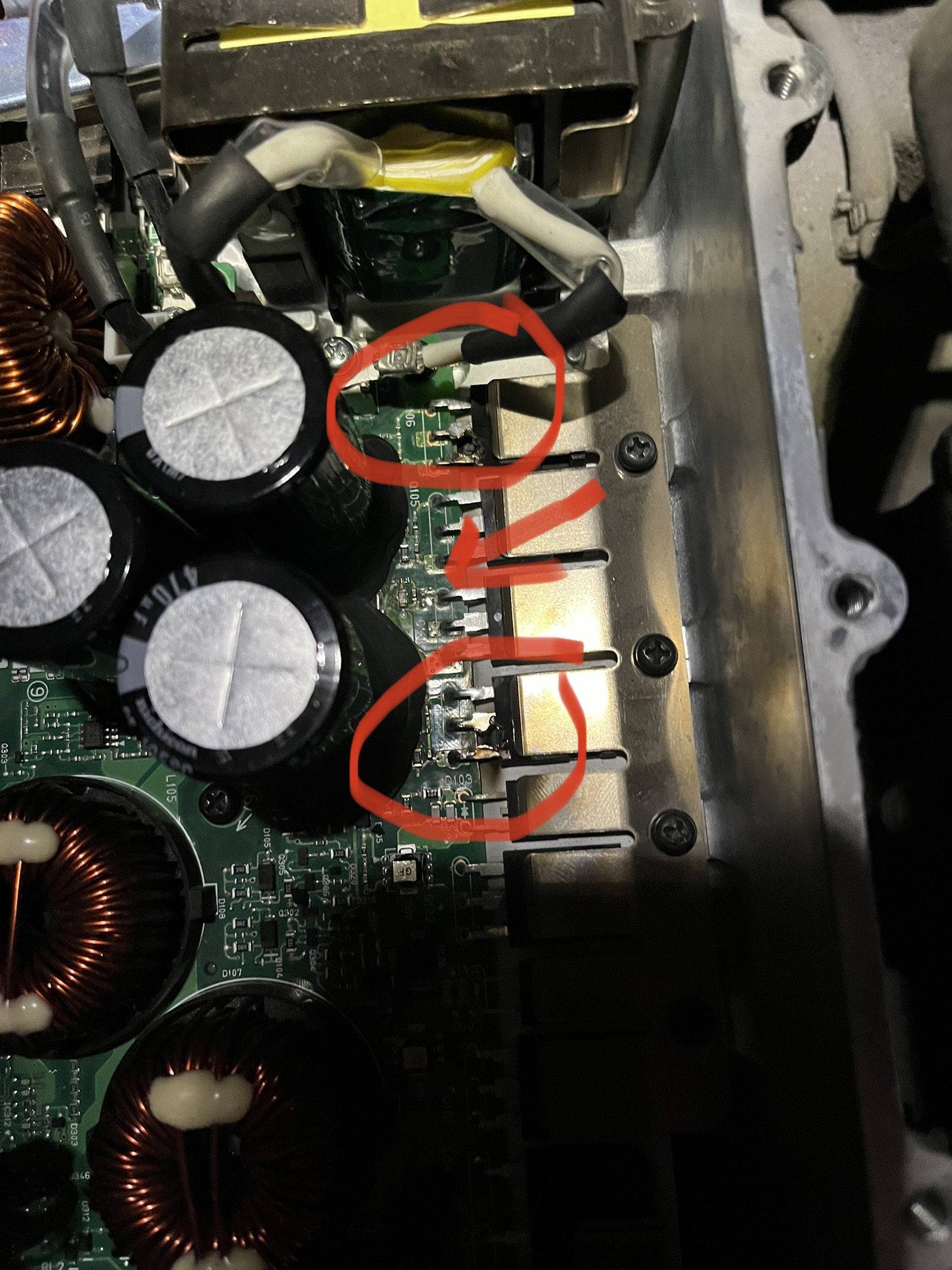
Also i don't understand how shorting by the snubbers caps would cause the MCU fuse to experience an over-current. If the snubber caps were to fail shorted, then the rectifier diodes in the waffle plate would likely fail and repairs would not be possible. Yet several have been repaired by replacing just the caps and fuse.
It makes perfect sense to me actually.
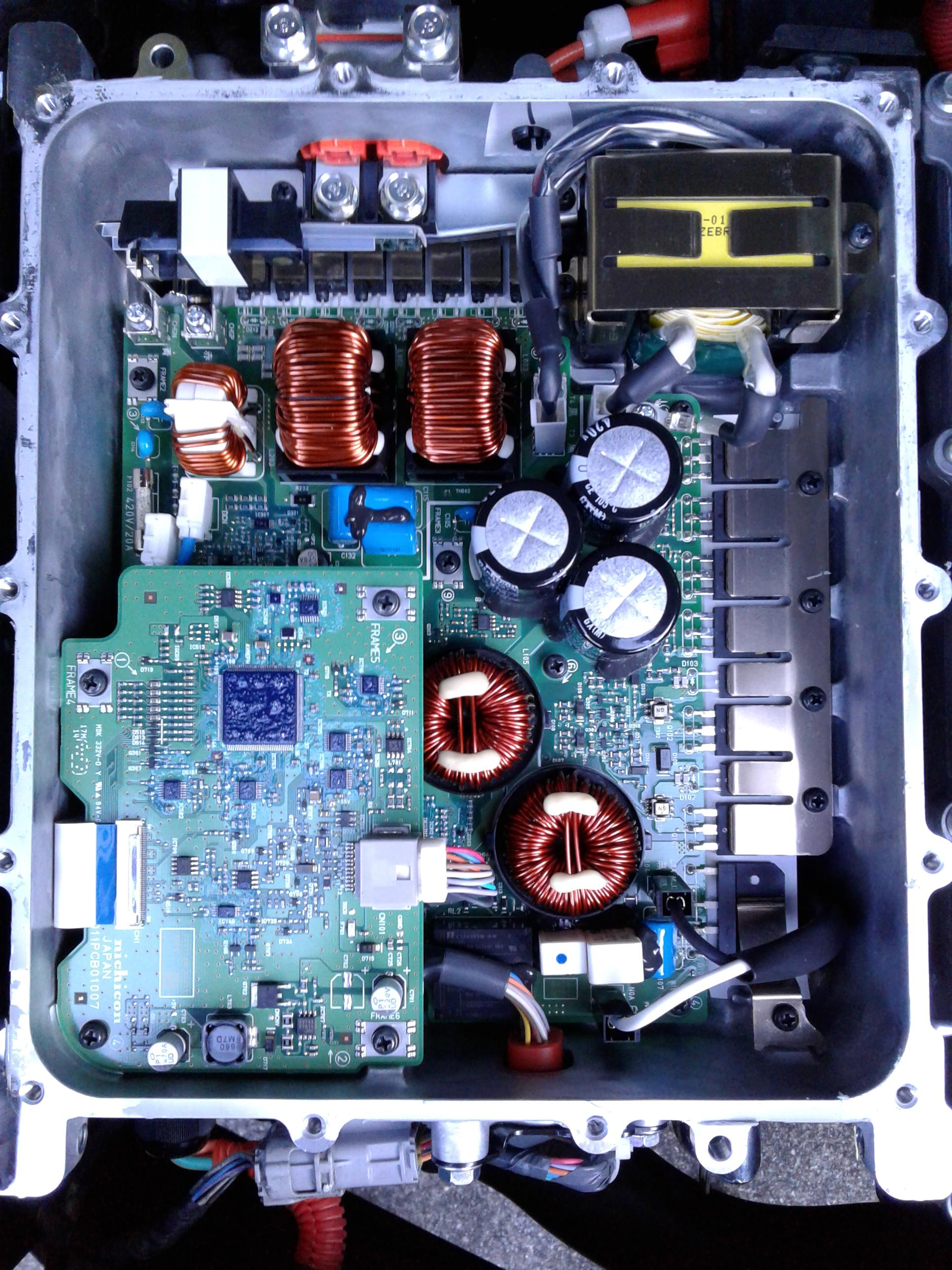
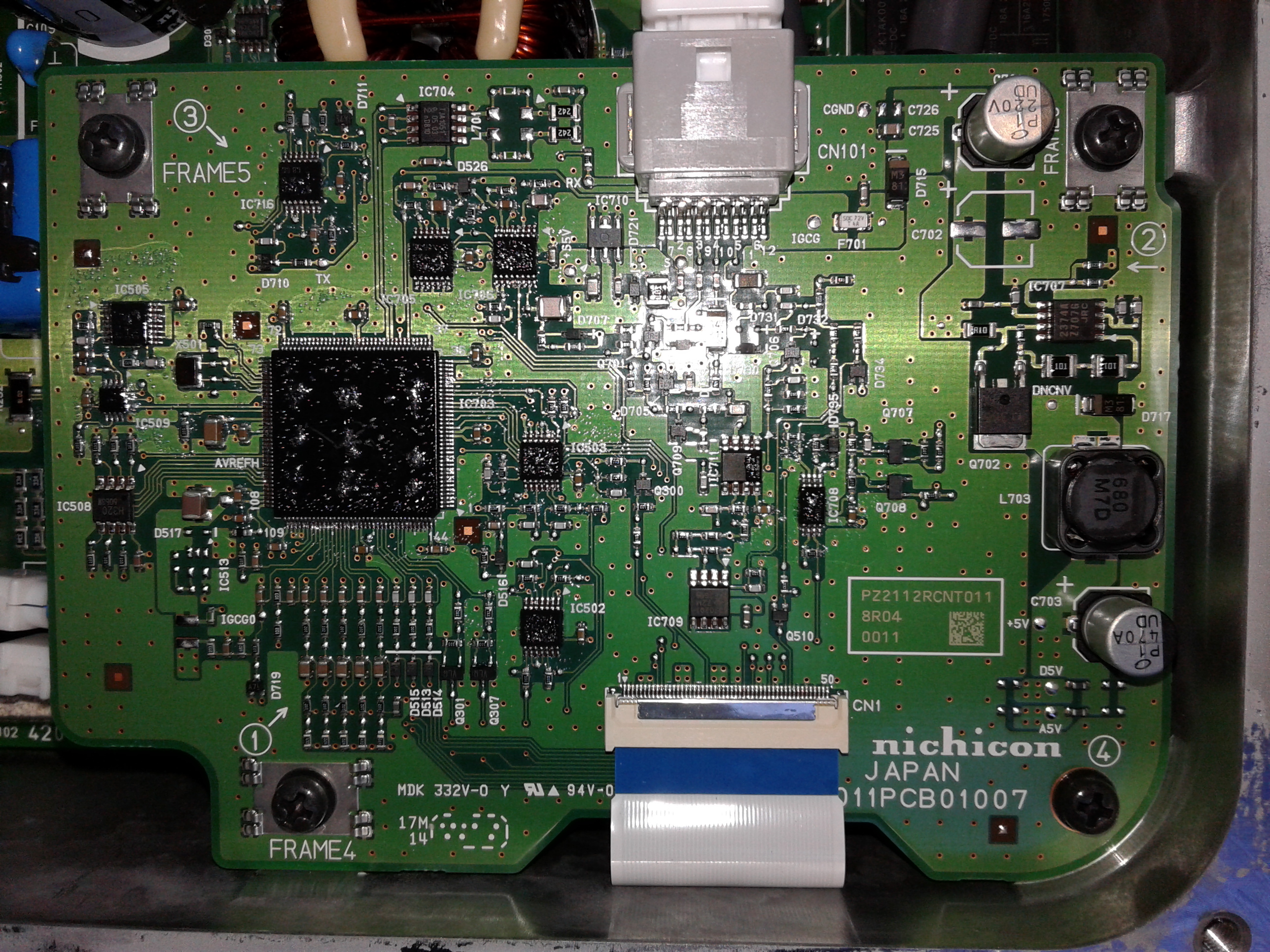
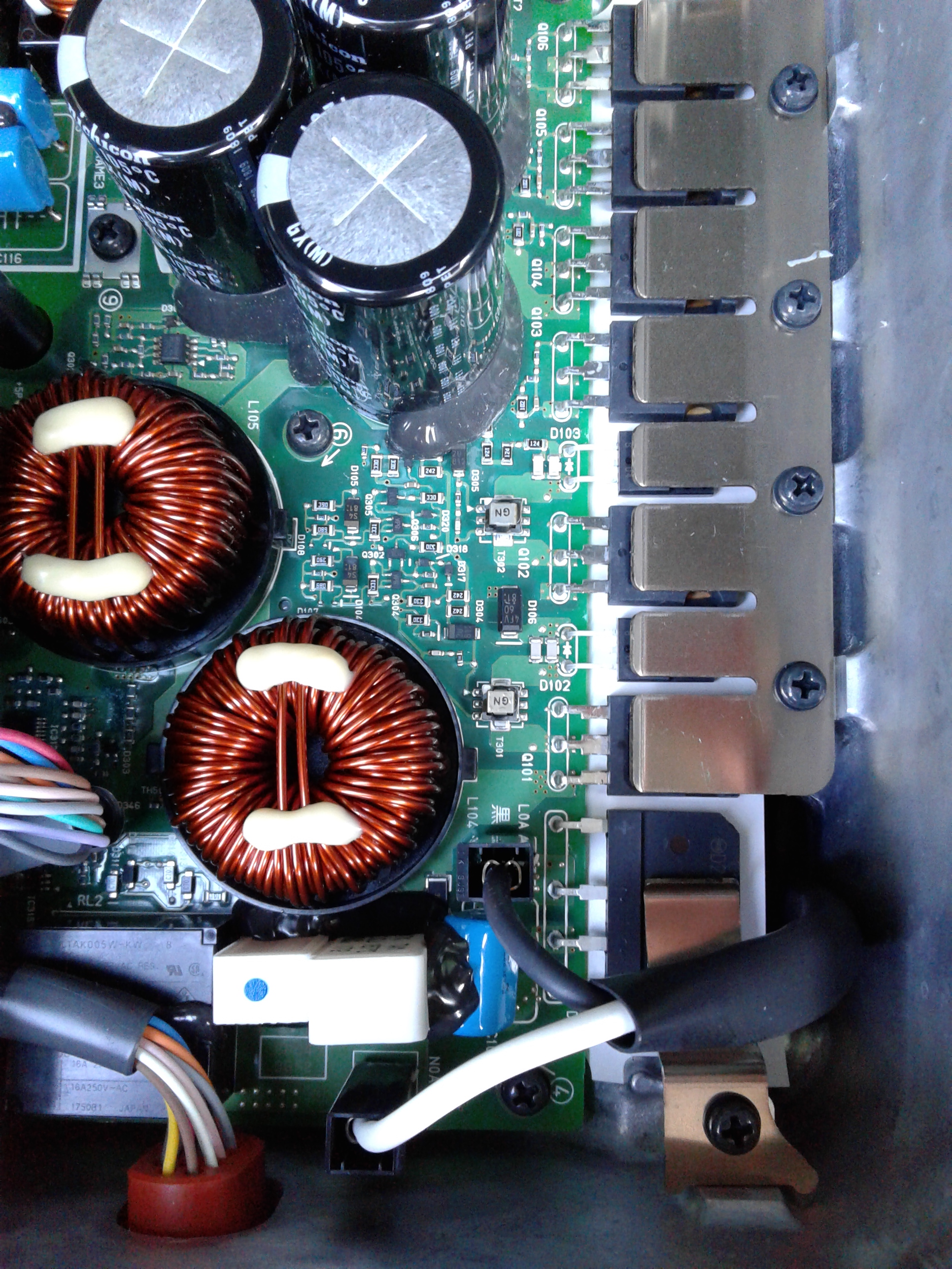
If you place a short across the 360v output of the on board charger (at the 1000pF caps) the charger electronics will have current limiting at or below around 10 amps and probably complete fold over protection so that it would shut down completely in the case of a short. This will protect the electronics of the charger proper, (including rectifiers) and also prevent the small fuse on the OBC PCB from blowing as the current will never exceed it's 20 amp rating unless the current limiting system failed. (And the fuse in the DC/DC converter is irrelevant as it isn't a fault current path in the shorted cap scenario)
However the only thing limiting the current drawn from the traction battery by the shorted cap is the 20 amp MCU fuse - nothing else is in the current path except the 250A fuse in the traction battery enclosure, and that's not going to blow first.

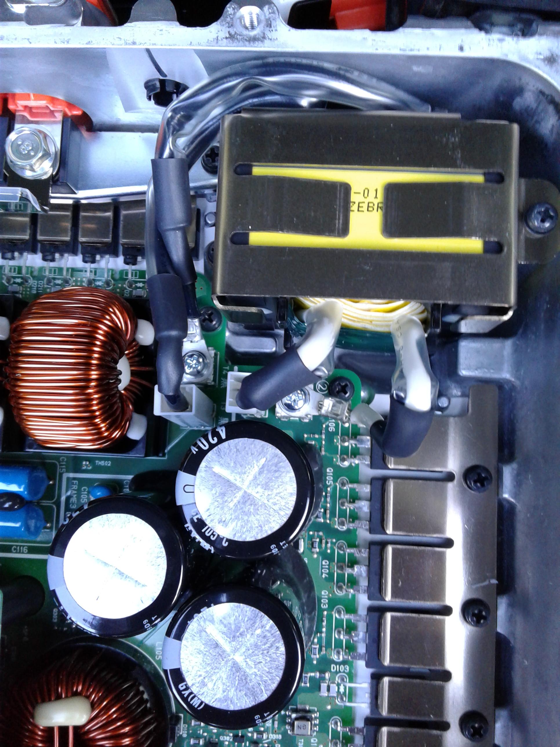
But i can see how an interruption of the OBC output current outside of the OBC, such as a mechanical break in the MCU fuse, could create an inductive over-voltage condition on the output side of the boost transformers that could cause the snubber caps to split.
While your theory of the fuse blowing first and causing an inductive spike is interesting and certainly feasible, occams razor doesn't require it IMHO.
I think it's as simple as a poor quality capacitor failing spontaneously well within its supposed limits, or perhaps being under-speced for it's role in the circuit or a bit of both.
Consider the following scenario - one of the caps goes shorted for whatever reason during charging. The OBC is already putting out ~10 amps in constant current mode. A short is not going to cause it to put out any more current because it is already electronically limiting to 10 amps. If it has fold over protection, and I can't see why it wouldn't, it will shut down if it continues to put out 10 amps but the output voltgage drops abnormally low. This protects the semiconductors from over dissipation and is easy to do - I've built linear regulators with fold over shutdown in constant current limit mode, and it makes them nearly indestructable done right.
Once the OBC shuts down the the risk of the OBC's own fuse blowing is gone, however the traction battery will continue to supply hundreds of amps until either the cap vaporises or the fuse or both.
If the cause of the failure is a defective capacitor spontaneously going short circuit and then blowing the fuse, I would expect to only ever see one capacitor of the parallel pair failed.
On the other hand if your theory about inductive spike due to a blowing fuse is right I'd expect to see both capacitors blown at least in some cases. Have there been any reported cases yet where both caps fail ? Certainly in mine one split completely into three pieces (blew the bonding legs off both sides of the ceramic chip) but the second capacitor was unharmed.
That to me suggests the capacitor failing was the root cause of the failure, and that replacing them with better rated (higher voltage, high current rating) types like I did is prudent.
