Battery pack change plans

Mitsubishi i-MiEV Forum

Help Support Mitsubishi i-MiEV Forum:

This site may earn a commission from merchant affiliate links, including eBay, Amazon, and others.
Inspect the daisy chain wiring for damage and connector contacts for corrosion. The CMU board contacts are gold plated but there could still be corrosion on the battery side.

What were the errant cell voltages reading before you "fixed" it?
no damage or corrosion visible all looks like new. The gold contacts were fine and did run a fibre cleaner over the battery terminals where they connect to the pcb but these same batteries gave no error when connected to the adjacent pack with cmu10 board.

Looking at the voltages on hobdive
All register 3.9x most of the time but cells E and F particularly vary a lot compared to others F especially drops to 0.09v before coming back to 3.9xx seems to be e f cells specially which alter constantly.

Is this typical of a cm fault?

Are both half parts of the boards specific or is the smaller boards which service cells e f g h inter changeable with any block. Assume it will not interchange with the red ones either?
 
All register 3.9x most of the time but cells E and F particularly vary a lot compared to others F especially drops to 0.09v before coming back to 3.9xx seems to be e f cells specially which alter constantly.

Is this typical of a cm fault?
Yes
Are both half parts of the boards specific or is the smaller boards which service cells e f g h inter changeable with any block. Assume it will not interchange with the red ones either?
Yes, the extender boards are interchangeable (not 100% about the red ones) but they are merely feeding the cell voltages/temp back to the main CMU board.

Unless there is a dodgy contact/wire the problem is most likely a faulty LTC6802-2 chip especially if the corresponding temperature values seem ok
 
Unless there is a dodgy contact/wire the problem is most likely a faulty LTC6802-2 chip especially if the corresponding temperature values seem ok
Is this chip easy to change once I have one? Used to do some PCB work with schools etching my own etc but never dealt with commercial pcb repair
will check temperatures on the OBD drive app
 
Not been sat completely still today - finished editing this about the BMS investigations I have done so not all waste. Hope it helps but here is proof that moving the CMU pcbs away from their designated positions does not confuse the car but you can only have one ID of each within the pack so only one CMU with an ID of 09 can exist but it does not matter where it is put within the pack the car will still recognise it. Certainly this was tested with the green type BMS boards
 
Further news
With much thanks to Mickey particularly who never seems to say no to try this and so got braver today

Have had the pack up and down from the car more times than I care to remember with much frustration and annoyance as more and more things did not fix.

Have tried as per video above moving the CMU to different positions and these seem quite happy regardless of where they go but I only tried two positions.

Kept getting a CMU09 fault and this was then triggering a charge error fault.

Eventually came to the conclusion that I need a new cmu09 board. However I have a stack of battery packs from the donor car but these are red BMUs
Was told from the start that green and red BMU are not compatible and so went back to look at the red one to find it very similar to the green one indeed. The data connections have one less cable used on the green on than the red ones but the colours are all the same.

Decided that it would either work or not so put the red CMU09 into the pack and reconnected the system up again (yet again) and turned on the car.

Battery meter fired up instantly and read higher than before more in line with the charge I had put in from the chademo the other day.

Checked cells voltages with OBD drive and all cells registered and were accounted for so clearly the red CMU09 is reporting to something OK.

Switched to Drive and the car gave me the green light and moved an ich each way - pack not connected to the car so cannot move really.

Checked with HOBDRIVE which was less happy and could not read CMU09 cell readings but would clear the DTC and not reoccur which is serious good news.

Pushed my luck further and heath robinson attached the battery coolant fan so it did not create a fault and plugged in the charge lead and hey presto we have charging too and battery meter has gone up two bars before I stopped it charging as it was not a complete pack

Massive good news as far as I can tell - not sure how long it will last or if it will drive ok but it does seem to me at the moment that the red BMU are forward compatible with the green BMU system even if they are not compatible the other way

Nice to prove that my spare donor car OBC charger does actually work but next job is to change back to the original one and see if that now works too as the donor car I am pretty certain will not attach to the house fast charger.

Reassembly and proper test tomorrow and report back
 
Nice to prove that my spare donor car OBC charger does actually work but next job is to change back to the original one and see if that now works too as the donor car I am pretty certain will not attach to the house fast charger.

Reassembly and proper test tomorrow and report back
Given that a lot of assumptions have turned out wrong in the course of this project I would try the car on the house charger once everything is reassembled.
Might as well test @kiev ‘s theory that they could work on both leads..
 
it does seem to me at the moment that the red BMU are forward compatible with the green BMU system even if they are not compatible the other way
I found this in my notes:
Notes said:
Red 8-cell boards have a D-pak transistor and associated components that are not present in the green boards. On red 4-cell boards, these parts are not populated.
So maybe the red boards have some feature that Mitsubishi decided was not needed, so they deleted the parts in the green boards. It's hard to imagine it working with the changes I have seen. But seeing it working (albeit not driving) is what matters!

Do your red boards look like this?

1723091893413.png

Edit: And do your green boards have that chip / transistor? On green boards I have here, there is an electrolytic capacitor in that location.
 
These are the two boards fitted together. The red one from 2010 car with a funny short vin the green from 2011 car.
Have had movement from car on drive with this one red board fitted to green pack but can only move inch each way as pack not attached to car doing that job now
Only issue is that when you switch off the battery light comes on and then extinguishes. That's all for now more if I can drive it properly... here is hoping
 

Attachments

  • 20240808_093011.jpg
    20240808_093011.jpg
    155.7 KB · Views: 0
  • 20240808_092752.jpg
    20240808_092752.jpg
    97.6 KB · Views: 0
  • 20240808_092747.jpg
    20240808_092747.jpg
    94.3 KB · Views: 0
  • 20240808_092743.jpg
    20240808_092743.jpg
    76.3 KB · Views: 0
2010 car with a funny short vin….
Actually my car (briefly) failed the NCT (Irish version of MOT) yesterday as the tester could not find the VIN no stamped into the chassis, apparently this is a local requirement in addition to the label on the door.

After a bit of head scratching and looking into every nook and cranny, Google came to the rescue; took off the right side panel in the boot (quarter trim lower) and there it was…
 

Attachments

  • 1723108978357.jpeg
    1723108978357.jpeg
    60.7 KB · Views: 2
After a bit of head scratching and looking into every nook and cranny, Google came to the rescue; took off the right side panel in the boot (quarter trim lower) and there it was…
Yes that is right - we had this issue at the start of this thread since everyone told me it had to have a certain length of numbers and my working car conforms and is fine but the donor car has a short version and the conclusion was it may have been an early batch of imports?
my working car is JMALDHA3WBU000262
my donor car is HA3W0001622 confirmed by the marks on the back corner of the car too
No idea why but that is what it says. donor car has tinted windows tinted lights different headlights no heated seat red boards and early charger and round pin type isolation red plug and a lot more substantial cover to the battery trays
Tis what it is but glad yours passed. Our UK one never seems to question it but it is a requirement too - thought it was on a windscreen corner?
 
Some brave testing and swapping has pushed the envelope of knowledge, bravo!

Those are great pictures to show some details and differences between the red-coated boards and the clear-coats, aka green boards.

The flex spring conducting wires of the clear coats replaced the flexible circuit boards of the red coats; 3 white flex blobs vs 1 blob plus 2 mechanical flex spring (non-conducting).

The D-pak transistor circuit would need to be traced out to determine the difference and function, but otherwise the boards look very similar.

Maybe the reds vs green is urban legend--don't remember how or where that got started.
 
Last edited:
Success - I have a working car again.

Put the battery pack back in properly but have left off the plastic shroud as plan to get the CMU09 green board repaired with new LTC chip and see if that solves the issue and stupidly I left out the plastic air flow thing over the front pack so have to be back inside the pack soon anyway but was desperate to see if a loaded accelerate under load test would work.

Happy to say it does - been for a short 2 mile ride up the road each way and booted the car and starts drives and is everything it was before. So the one red board has worked and does not throw up any battery issues etc
The only thing I do get is a brief battery light on and off when I switch the car ignition off

Put it on charge and the original 13amp non brick lead works with the car and its currently getting a slow charge - we know the chademo works but the car will not recognise or even light up the red plug on the dash when either the brick charger or the house charger is plugged into the car at all.

At the moment the car has a the 2010 car charger fitted and its working so happy - this is the charger dated 2015 but from the 2010 car with the funny short VIN number
I will when I get around to it refit the original charger to the car and see if the brick and the house charger then work on this as pretty certain it was a battery issue that stopped the charger from working not the charger etc.

Video on the red green boards to come but not done it yet..

But despite all the odds I have a working rescued car!
 
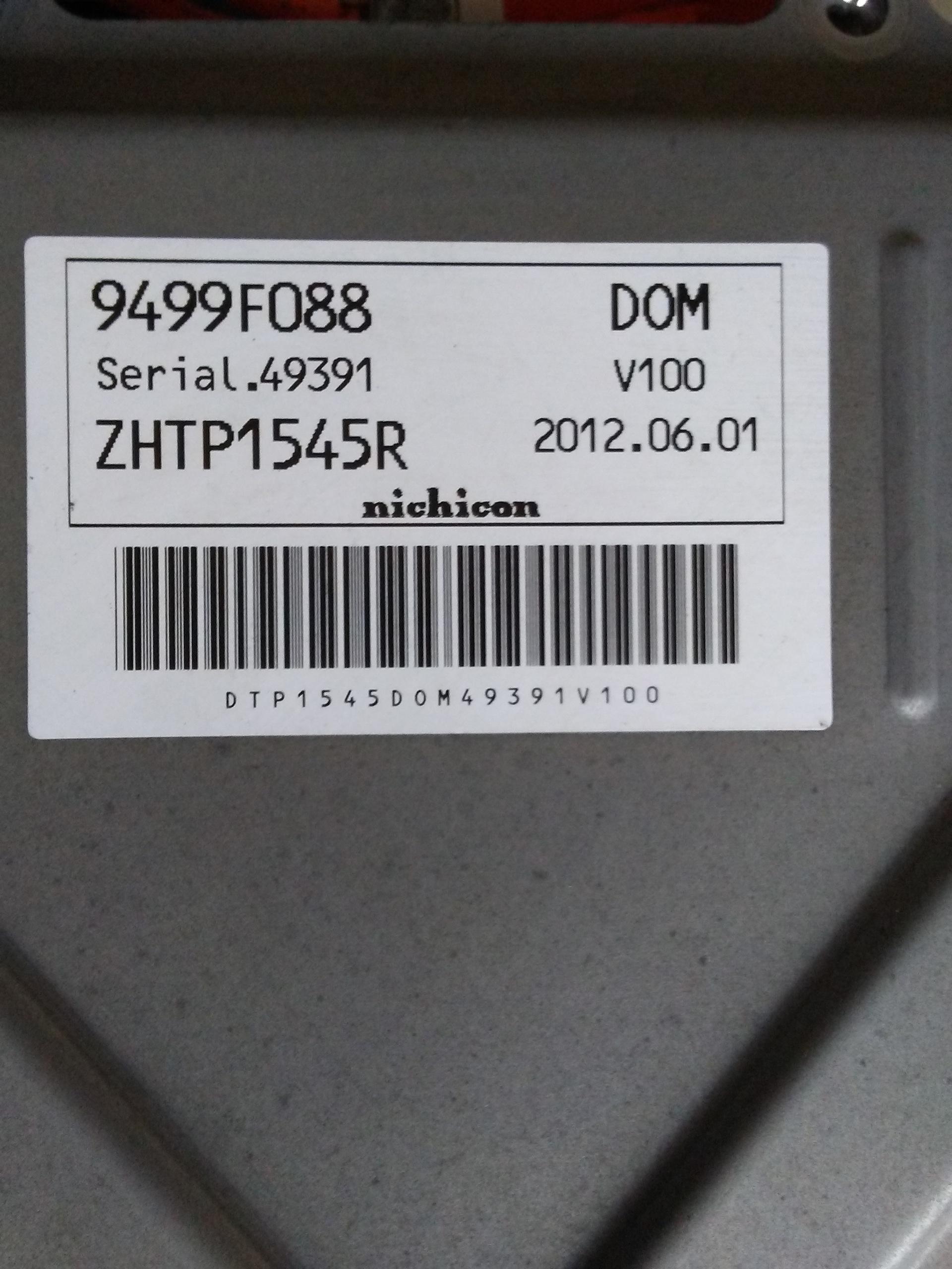
The label on the OBC might have some clues. i have only seen the 9499xxxxx OBCs that use the black box EVSE to charge.
1cjqhQ8.jpg


i had a later gen2 model installed to replace the original, and it had a different part number, 9481xxxxx.

It would be interesting to find the part number for 2010 that use the plain cable EVSE (no black box with relay), to see if there is something in the p/n code, or the Nichicon part number, that might point to this.
 
my black box charger has code 9499xxx but my early charger dated 2015 has 9481 code

assume I have to live with the situation and not use the house charger or change the OBC back to the the original 2011 one and see if this actually works then keep the 2010 early one as a spare.

This is now the next problem once the green BMS comes back from repair and see if that works then.
 

Attachments

  • early charger no box.jpg
    early charger no box.jpg
    75.9 KB · Views: 0
  • black box charger.jpg
    black box charger.jpg
    88 KB · Views: 0
More
Have now sent off the damaged BMS board to be hopefully be repaired.

Been out in the car tonight - forgotten how delightful it is to drive and nice to have less range worry knowing that the powerpack is much better than before. Still no DTC issues and even the battery flash on when key off seems to have gone now too.

Finished this which has proof of a working car on the road under load and speed despite having one RED BMS board within the pack of GREEN ones on the car. The green data cables which read the PCB has one less wire in the plug than the RED ones which is perhaps why they are backward compatible but not the other way around.
Hope this draws an end to my headache - learnt a massive amount and enjoyed but still have to sort out the charger so I can use the house one again


Please like (and subscribe) if you like this
 
These are the two boards fitted together.
Your red board even has some parts populated that mine doesn't. But perhaps that's because mine is a 4-cell board (no connector at the bottom). Quite a lot of the parts disappear at that end for 4-cell boards.

I removed some of the red coating to be able to make contact with the test points. I might have even replaced the LTC chip on this one, I can't recall. The soldering looks messy enough to be my shoddy work 😳

We have the same PCB version: 2.1.5.

1723174594968.png
 
Success - I have a working car again.

Put the battery pack back in properly but have left off the plastic shroud as plan to get the CMU09 green board repaired with new LTC chip and see if that solves the issue and stupidly I left out the plastic air flow thing over the front pack so have to be back inside the pack soon anyway but was desperate to see if a loaded accelerate under load test would work.

Happy to say it does - been for a short 2 mile ride up the road each way and booted the car and starts drives and is everything it was before. So the one red board has worked and does not throw up any battery issues etc
The only thing I do get is a brief battery light on and off when I switch the car ignition off

Put it on charge and the original 13amp non brick lead works with the car and its currently getting a slow charge - we know the chademo works but the car will not recognise or even light up the red plug on the dash when either the brick charger or the house charger is plugged into the car at all.

At the moment the car has a the 2010 car charger fitted and its working so happy - this is the charger dated 2015 but from the 2010 car with the funny short VIN number
I will when I get around to it refit the original charger to the car and see if the brick and the house charger then work on this as pretty certain it was a battery issue that stopped the charger from working not the charger etc.

Video on the red green boards to come but not done it yet..

But despite all the odds I have a working rescued car!
Great i am happy for you
 
Repaired CMU board due back today and will then be able to test it and see if its fixed - will mean the battery pack gets dropped a fourth time but...

Been thinking about the charger situation - currently got the early standard UK 13amp type plug no black box type charger on the car which works but will not work with the house charger or the black box type lead - does not even recognise that its plugged in.

It has been suggested that I could modify the wiring to accept the later black box and house charge lead but this seems to think that the car is looking for an earth and using a 100 ohm resistor between neutral and earth lead however cannot see how this will work on leads designed to work with this type of car anyway.

Anyone got any suggestions how I might be able to modify the charger on the car to accept the house charger especially - not bothered about the black box
Quite happy to experiment but also plan to eventually try the original charger back on the car as certain that it is not broken and it was the CMU board that was making it drop out from charging.

But before I change it over again thought I might try to see if I can resolve the issue. At least I know I have a working spare and a way of operating it.
 
Back
Top