No READY. P1A15 error. Condenser charge timeout.

Mitsubishi i-MiEV Forum

Help Support Mitsubishi i-MiEV Forum:

This site may earn a commission from merchant affiliate links, including eBay, Amazon, and others.
a via is a plated conducting thru hole in a pcb, either to the other side or to an internal layer.
i think i fixed the link so it should show in the post.

Here it is again
UFACkBPl.jpg


if you can put a scope on the output pin 3, see what it looks like, then move it up the board to the junction above the tiny resistor of the output low pass filter, and compare how it looks? Maybe the LPF is leaking and pulling the output voltage low?
 
that tells me that the op amp is okay and doing its job. You are getting the same 0.15 voltage difference that Gencis found in his testing.

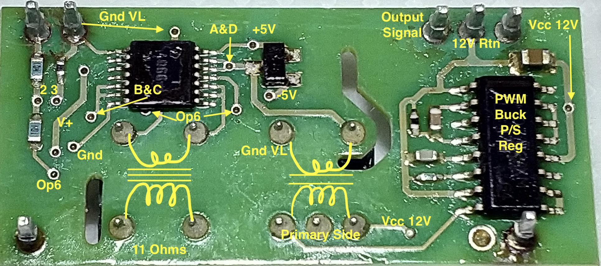
All measurements are between one via or pin and ground.

if you can put a scope on the output pin 3, see what it looks like, then move it up the board to the junction above the tiny resistor of the output low pass filter, and compare how it looks? Maybe the LPF is leaking and pulling the output voltage low?

That little resistor measures 275 Ohms on my board. i'm hoping that one of those capacitors of the low pass filter is leaking signal to ground and causing this fault. [That would be the easiest to fix].

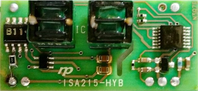
That ic on the right is a 4066 switch. Pin 1 is the bottom pin on the right side.
The control gates are held up by the voltage divider of the leftmost upper via.
The input signals from the other transformer come into pins 1&4 for the first half of the oscillation, and pins 8&11 for the second half of the oscillation. Could you look at those on a scope to compare that they have the same looking waveform, and what is the frequency?

The gated output appears on pin 2&3 for the first half and pins 9&10 for the second half. These get routed to the LPF and on to the output pin 3.

The output of the OpAmp gets switched by the 4066 on the bottom side thru the transformer on the left; the output of that transformer gets sent to the 4066 on the top side.

Here is the bottom layer of the hybrid for reference
aydmOQY.png
 
aydmOQY.png


Now I think im onto it

Hopefully the picture above of someone elses is available

On the 12v side I have positive coming in on pin 5 and return on 4

with a regulated supply of 11.94v.................... this is correct across pins 4 and 5, but after the small blue resistor, the via on the picture and the terminal on the transformer there is only 10.75 volts???????????????????????
 
you might be on to something. That seems like a big pull down-- What is the current limit of the supply?

But it comes out to only 12mA across that 100 Ohm resistor would cause that voltage drop. So not so sure, i measured 20 mA on my board, but didnt measure the drop. The capacitor next to it measured 800nF.

Maybe a current measurement would be in order for the 12V supply.

Did you ever measure the low voltage supplies over on the 5-pin chip (i think it is a single gate logic inverter chip)? pin 1 is the lower right side, then from the via of pin 3 to ground and the via of pin 5 to ground.
They supply the power for the op amp and are created from the 12V.

a cotton swab with alcohol can provide localized cooling of components when you get ready for that sort of testing.
 
Its a 600ma supply

The draw on the 12v circuit it 35ma, slightly more than yours, this would be because of a heavier load?

not checked the 5 pin chip, which circuit am I grounding this too, VL or 12v-

I dont have any alcohol but can warm the resistor and capacitor

when looking at the picture of the rear of the board, there looks like a larger capacitor between 12v + and -
 
Heating the corner of the board with 500 degree hot air blower where the 12v input is causes the voltage after the resistor and capacitor to drop from 10.75v to 10.51..........

So shall I take the board off or do I need to remove the capacitor and check first, then perhaps replace the resistor, should there be a voltage drop over that resistor and capacitor?
 
The low voltage supplies are with respect to the VL.

There should be a drop across that resistor and capacitor filter depending upon the current draw.

Does the 0.15V difference between the Input and Output of the hybrid still exist after the thermal test?

Any liquid on a swab can create cooling, but alcohol evaporates quickly and is nearly instant cooling.
a soldering iron can be held near a component to provide some localized heating also.

It sounds like the resistor has shorted out internally? 13 milli Ohms? or MegOhms? Be sure to scratch off the clear coating to get a good contact (the board is coated).
 
Since the test heating it, I sprayed some pcb cleaner to cool it, the 12v input voltage has only recovered to 10.6v, before I heated the board it was 10.75

Another test now, the output voltage on pin 3 when 20 degrees started off at 3.804 and after heating the same corner rapidly dropped off to 3.713

After this second test my input voltage after the 100 ohm resistor is 10.41
 
Looks to be 0603, 1% by the blue color. Scratch the clear coat and measure again. It can't be open or no current would flow. Or your meter is reading across the capacitor somehow.

Spray the pcb cleaner under the hybrid corner to cool that big filter capacitor between 12V and ground, then check your I/O and voltage drop.
 
The resistor and capacitor are in parallel across that part of the circuit so maybe.

But realistically should I be having nearly 1.5v drop?

Is it time to start removing components! I have 0603 package resistors but not sure if they are 1%
 
OH NO.


The problem is now that without doing anything more, the output voltage is bang on 4.01

WTF can I do now!!!!!!!!!!!!!!!

I really appreciate your help KIEV because we are pinpointing at least my problem!
 
1.5V drop across a 100 Ohm is only 15mA. The primary coil of the transformer winding is 13 Ohms, but the "12V" is being switched thru the winding at a high frequency, so there is not going to be nearly 1 Amp thru the winding.

i don't think your resistor is bad and no need to change it.

use localized heating and cooling on individual parts to isolate them--the high temp hot air blower hits everything.

Measure the +/- "5V" low voltage supplies; they are created from the "12V" and if they are mismatched then that might cause the 0.15 offset.

Realize that the '12V' may be powering up stuff on the control board too.

[edit] just saw your post that it is "Fixed", but at least there is confirmation that this has a thermal element involved.
 
Back
Top