No READY. P1A15 error. Condenser charge timeout.

Mitsubishi i-MiEV Forum

Help Support Mitsubishi i-MiEV Forum:

This site may earn a commission from merchant affiliate links, including eBay, Amazon, and others.
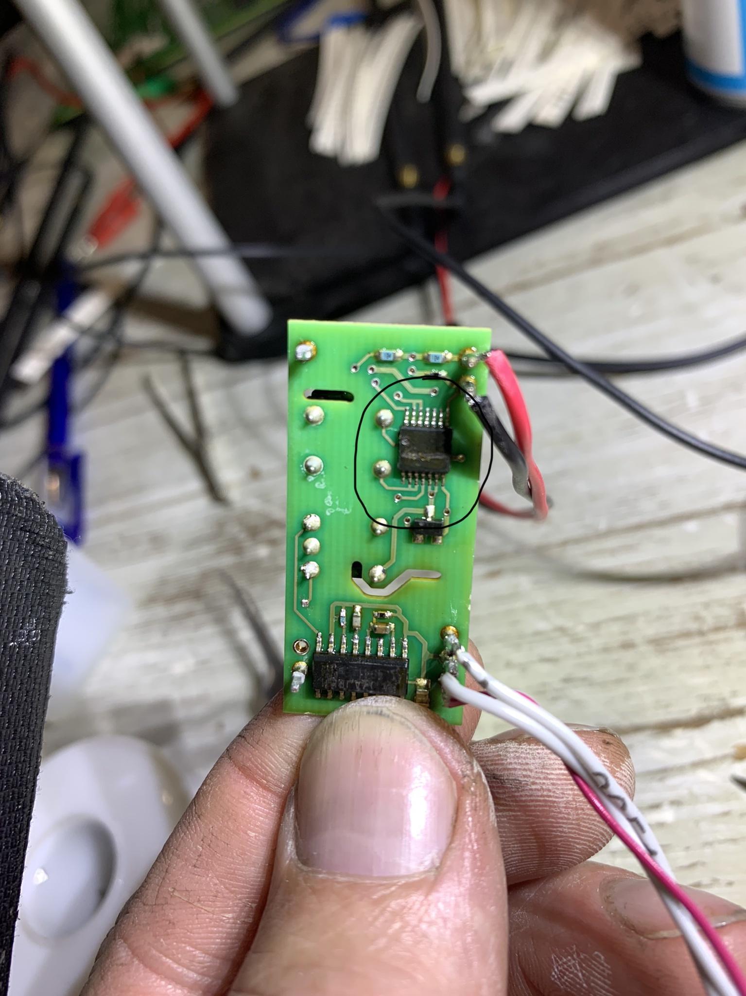
Heating that corner of the board has caused the output to drop off to 3.83 volts again

The input 12v after the resistor has stayed constant to that part of the circuit is probably ok.

It must be time to take the hybrid board off and test so I can see the bottom of it, at least this is where the whole fault must be stemming from
 
Those ceramic chip capacitors can get stressed due to soldering such that they bend and crack partially, which causes them to internally short partially or intermittently due to thermal changes. That's why i think they are hideous evil little monsters. i suspect that big one on the bottom corner is the culprit; if it shorts it will pull down the 12V supply rail at the via where you were measuring.

[added after seeing your post]

if the 12 V was holding up (came back up to 10.75 or did it go higher?) then the large cap on bottom is not shorted, but the Output signal dropped, then check the two capacitors and little resistor on the Output pin 3 of hybrid. Those two caps could be leaking to ground and pulling the Output down.

Use localized heating with the tip of a soldering iron near the capacitors, one at a time and watch the voltage on Output.

Another test if you wanted to heat the corner again--is measure the +/-5V supplies, then monitor them while you are heating the corner. i haven't seen those readings. This might help point to whether the issue is on the top side at the output, or in the PWM chip on the bottom.
 
The board is now off and wired up

the voltage is about 3.8 on the output and doesent drop off unless heated, I have removed the lower capacitor and now have 3.54v

what are they meant to be and maybe I can replace them if I have the right ones?
 
So the output is low by about 0.2 volts with the big cap, then drops even more when the cap is removed?

109nF is like 0.1 uF, the larger size is to handle higher voltage. Can you inspect under a microscope looking for cracks?

i don't understand why the output drops when the cap is removed--does the 12V power supply hold up during that time or is it pulled down too.
 
I have replaced the two capacitors now on the top of the board, still the same

do we know exactly what chips they are on the top and bottom of the 12v end?

the 12v supply is stable and on the other side of the resistor is stable @ 10.75
 
I’m 99% sure it’s this chip on the lower of the board, do you know it’s specification please

The more heat the less output on pin 3 and the more cooling it rapidly brings the voltage back up but not to input voltage

I have only seen input voltage once

https://imgur.com/gallery/bfZgZ9x

bfZgZ9x
 
At the 15V end, on top is a TC4066 Quad Switch, and underneath is the TL494 PWM controller.

The one you have black circled is the other TC4066 Switcher. It is underneath the signal transformer over on the Input side, not the 15V side.

I3s91m8.jpeg


Top Layer ICs:
AD8677 Op Amp
5-pin single gate logic inverter, part number ?
3-pin dual diode, part number ?
TC4066, Toshiba Quad Bilateral Switch
2 transformers: Left one is 1:1 signal; Right one is 15V primary to +/- 6V secondary power.

Bottom Layer:
TC4066, Toshiba Quad Bilateral Switch
TL494, PWM Control Circuit for SMPS
3-pin dual diode, part number ?
 
Last edited:
Can you please check the voltages of the 5-pin logic chip with respect to VL on the top side toward the Input? And monitor its output pin 4 while applying heat or cooling that creates the change.

That controls half of the switcher outputs and would degrade/lower the OUTPUT voltage if it were not working properly.

Or these can be measured from the bottom if easier since you have it off. Please verify the +5, and -5 wrt VL, then compare the waveforms of B&C to A&D for symmetric amplitudes but 180 degrees out of phase. Or an RMS meter voltage reading would show any difference with respect to VL.

Check the two caps in the middle of the top side under the power transformer, although if the op amp is working okay i would expect them to be okay, but it doesn't hurt to check and verify every thing.
 
Well enough for one night Kenny, but Its the one which makes the most difference with temperature change

When I put that number into google it looks nothing like the one I circled, the one I circled has 14 pins?

I want to get as many components as possible and replace one by one

The only thing to aid my diagnosis is that I have seen the correct voltage returned once and now it has defaulted back again so good news, more so if a new component fixes the fault and we have start up! Or ready in this case :)
 
Okay sounds good, i'll post a link to the datasheets.

TC4066: https://toshiba.semicon-storage.com/info/docget.jsp?did=18707&prodName=TC4066BP

TL494: https://www.onsemi.com/pdf/datasheet/tl494-d.pdf

5-pin logic inverter, pn etched off, but close to this: https://www.onsemi.com/pdf/datasheet/mc74hc1g04-d.pdf


What's the make and model of that long probe test fixture you were using--i've never seen one before.
 
I dont know who made it, im sure it was from ebay, ill try and find it for you

Its superb for ecus and saves soldering, the probes are very heavy and the contact pins at the bottom are spring loaded so you get a positive firm contact. I dont like to disturb anything if I dont have to. As with this job it could well have all gone wrong if the correct voltage had progressed to be present.

I have done one final test before bed, the lower chip was cold and no voltage applied for ten minutes, I reapplied voltage and heat more localised and the output rapidly went from 3.84 down to 3.5 in a space of less than 10 seconds.

Many thanks for your help
 
https://www.ebay.co.uk/itm/LED-BDM-FRAME-PROGRAMMER-FOR-KESS-KTAG-FGTECH-KESS-KTAG-ECU-4-PROBE-PENS-UK-k-/174501333559?mkcid=16&mkevt=1&_trksid=p2349624.m46890.l49286&mkrid=710-127635-2958-0
 
The reply I got from the supplier of the hybrid board


ISA215-HYB is already discontinued and
don't have any substitutes.

Sorry for your inconvenience.

Best Regards,
Norie Nemoto
 
Sandrosan said:
Hi all,

Can theoretically the signal transformers on the hybrid circuit be demagnetized so the gain is reduced and then the voltage signal too?

We should consider that these transformers are close to the motor that should generate a strong magnetic field and after so many years some effect could happened.
They are transformers, not magnets. They can be magnetised, by the current applied to the primary winding, and the magnetic flux created by this current will induce current in the secondary. The magnetic cores are made from ferrite, which is highly permeable but has negligible remanence.
Further, the strong magnetic fields in motors act between stators and rotors, or field coils and armatures, with very little external leakage.
 
boothegermanshepherd said:
one last question

I looked at the spec sheet and it looks like TC4066BFT?

Is that the right package? And is a hc4066 compatible in the same package?

[EDIT: Should be compatible, but in this case not due to the power supply limitation of the HC.]

Yes it is the BFT in the TSSOP-14 package from Toshiba; and yes the HC4066 in the same package is compatible. All the 4000-series CMOS logic chips are interchangeable by number. The HC is probably a newer and faster device too. i generally try to find the datasheet for the exact part used on a board just for tracing purposes, but newer compatible parts will usually be available.

The TI SN74HC4066 datasheet shows a better functional block diagram of the device,
https://www.ti.com/lit/ds/symlink/sn74hc4066.pdf
 
Eddie49 said:
Sandrosan said:
Hi all,

Can theoretically the signal transformers on the hybrid circuit be demagnetized so the gain is reduced and then the voltage signal too?

We should consider that these transformers are close to the motor that should generate a strong magnetic field and after so many years some effect could happened.
They are transformers, not magnets. They can be magnetised, by the current applied to the primary winding, and the magnetic flux created by this current will induce current in the secondary. The magnetic cores are made from ferrite, which is highly permeable but has negligible remanence.
Further, the strong magnetic fields in motors act between stators and rotors, or field coils and armatures, with very little external leakage.

Thanks for the explanation Eddie49
 
Good morning,

Here we go, the last nit of testing from cold.....

With no heat applied and the ambient temperature at 18 and the hybrid pcb off and on its own test bench now.

4.00v going in

3.90v coming out


I work that out at a 2.5% drop without even any heat

If i very slowly warm the underside chip with a cool 200 degree soldering iron, the output drops until about 3.6v, bearing in mind that the chip is then probably 150-200 degrees, that is a 10% drop

Lets take our real figures if it was on the vehicle, my input was 353v at the battery so this less 2.5% would be 344v. I cant remember the figures but a 10v drop is probably where the problem lies.

If the ecu was warmer then this could be anything up from 10v, I dont know what the threshold is but sure that it would only expect a 1% variation at the most.


Now all we need to do is wait for my components to arrive!!!!!
 
Back
Top