Wrecked i-MiEV Battery Pack Discussion

Mitsubishi i-MiEV Forum

Help Support Mitsubishi i-MiEV Forum:

This site may earn a commission from merchant affiliate links, including eBay, Amazon, and others.
4hcGpRp.jpg


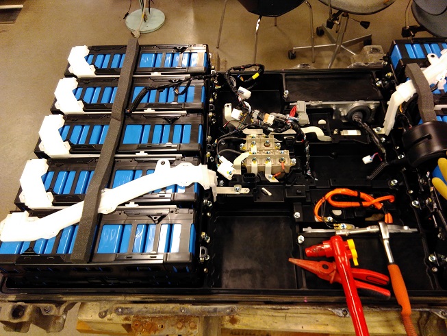
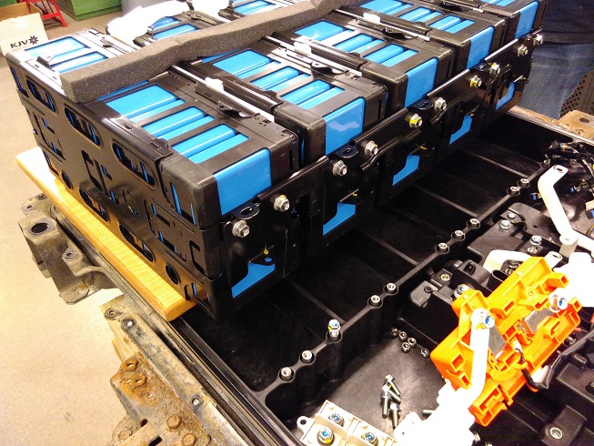
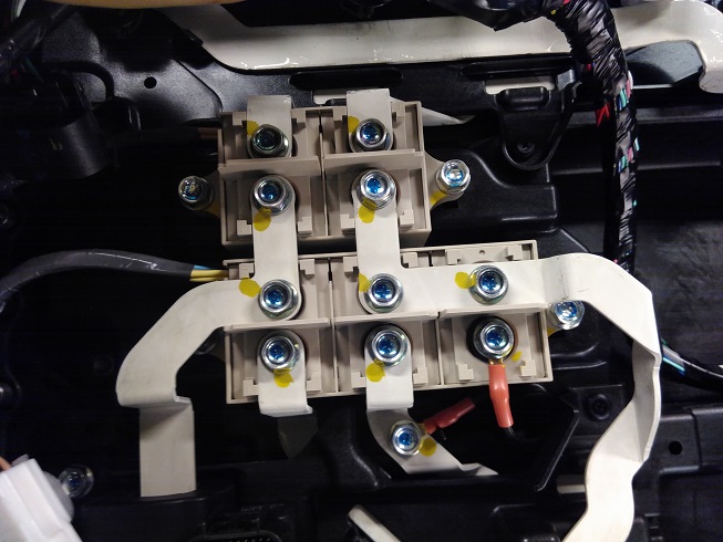
I count 5 contactors. Each contactor has two lugs on it (upper and lower).

1. Top Left - QC Negative Contactor
2. Top Center - QC Positive Contactor
3. Bottom Left - Main Negative Contactor
4. Bottom Center - Main Positive Contactor
5. Bottom Right - Main Pre-charge Contactor

The L shaped bus bar in the middle right connecting the upper lug of contactors 4 and 5 and the lower lug of contactor 2 is Battery Positive (Caution, live voltage present on this bus). The other bus bar to the left, which connects the upper lug of contactor 3 and the lower lug of contactor 1 is the Battery Negative.

The bus bars connected to the upper lugs of contactors 1 and 2 go to the QC port connectors on the outside of the pack.

The bus bars connected to the lower lugs of contactors 3 and 4 go to the main HV connectors on the outside of the pack (where the wires from the MCU connect). The wire connected to the lower lug of contactor 5 goes through a pre-charge resistor, which terminates on the Main Positive bus bar (the wire below contactor 4).

I'm not absolutely certain on this configuration, but it aligns with what I've read in the Technical Information Manual about how the car's HV system functions.

The construction of the case seems over-complicated compared to other packs I've seen. Tesla's pack is a work of art.
 
Thanks, it's great to finally have a visual of what's been long-discussed! Those two QC contactors would be key to charging with an offboard charger, or using a secondary battery pack for range extension. For a secondary pack, a second i-MiEV pack would certainly do, but any lithium battery with a couple more cells than ours should work by fully discharging itself first, so that we can then disengage the auxiliary pack and have a full main battery. (though we'd have little to no regen when using an aux battery with slightly higher nominal voltage). It shouldn't be hard to manually engage the QC contactors, bypassing all the CHAdeMO chatter, and if the car is in "READY" when you do so, the BMS and associated Coulomb counting would keep the original pack happy. The only unknowns I'm concerned about would be error codes or a shutdown from the nanny systems, but it sounded like success when siai47 did it.
 
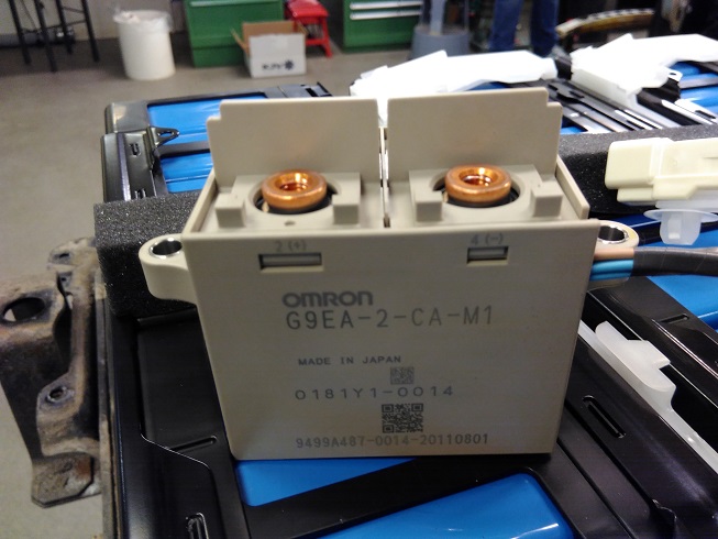
Main contactor:

2I9XTvP.jpg


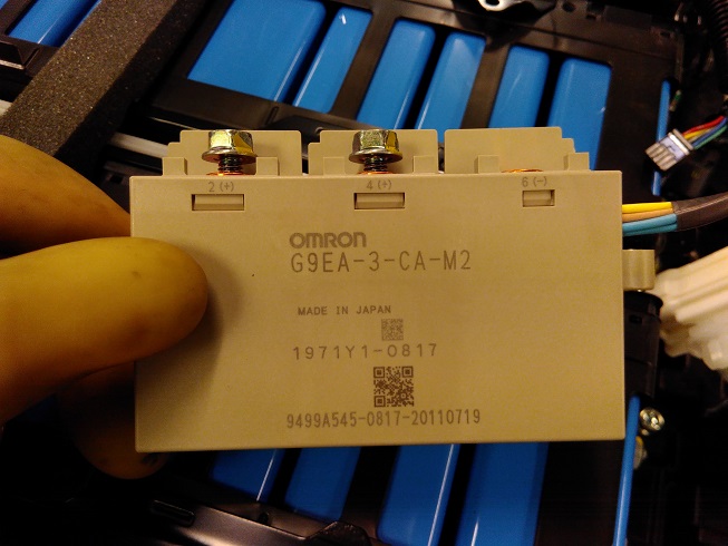
Here's the chademo contactor:

lkHgRl6.jpg


So we got to work a step further by loosing the packs.

kAJkGQ6.jpg


disconnected the wires for the cell-BMS-boards

3hmfgLA.jpg


sDFjlQM.jpg


And prepared the cells for removal from the frame:

gyubIFf.jpg


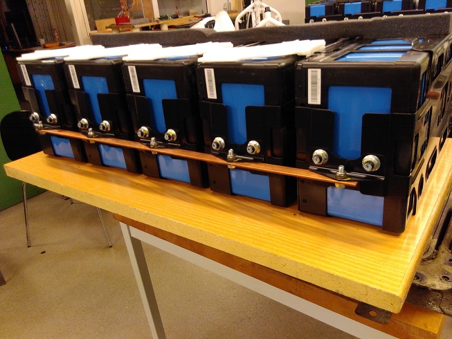
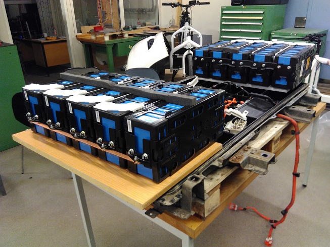
We found how attaching a solid piece of steel at the outer end of the 5xLEV50-8 we would have all of the 5 packs fixed at both ends. This due to the LEV50-8 packs already being fixed together on the side towards the center of the frame. Sure lifting 75kg of batteries (5xLEV50-8) is unhandy however having a piece tying them together could work in keeping the cells in place and reuse the buss bars. Just taking the cells out of the plastic bay and out of the securing fixing points of the bay causes the LEV50-8 cells to twist and breaks the buss bars if lifted up all together. We put a piece of wood below as additional support in preparation for removing them from the battery frame.

YLbDq2n.jpg


01vrkay.jpg


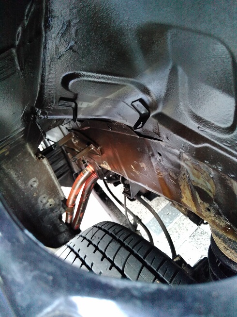
Taking a look at where best to connect the HV wiring on the car as considering a solution via the chademo inlet.
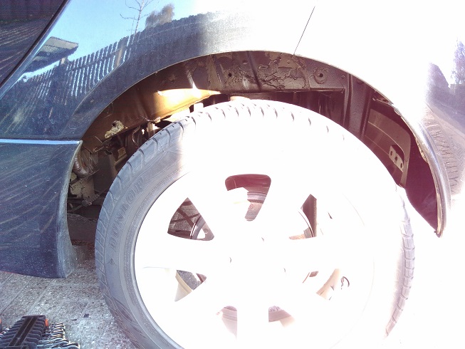
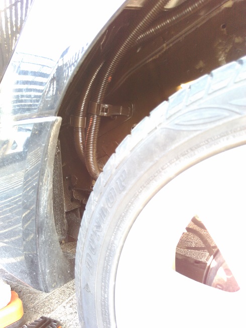
I took out the plastic cover surrounding the wheel below the chademo inlet.

3hP8zxp.jpg


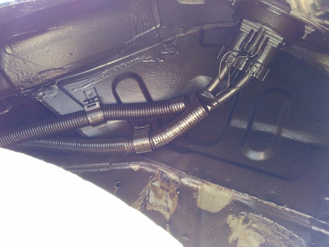
The brown'ish colour covering the ducting and others will be rust-protection.

LIJVn2B.jpg


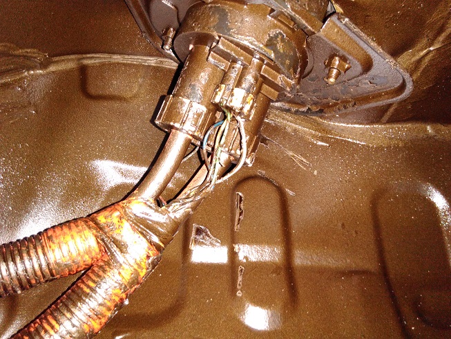
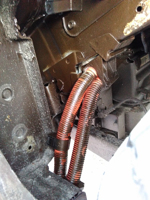
So I am looking for options of how to tap in on the Chademo HV wires. Looking to where there could be space to fit the contactor and HV wires coming from the 2nd pack.

wvyr2jp.jpg


hNKYuFF.jpg


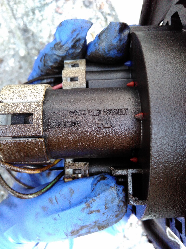
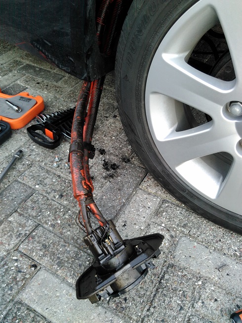
To get more space I took out the inlet:

QHRJHNB.jpg


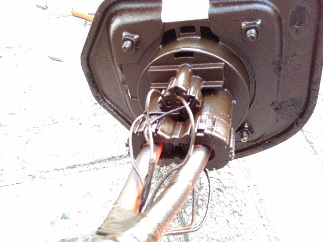
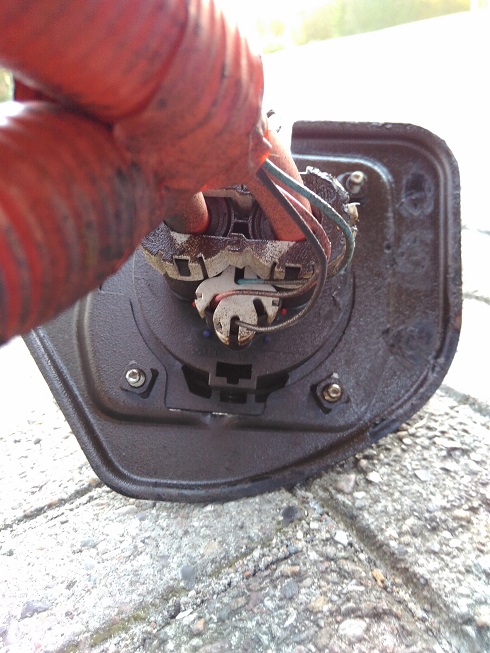
And checked for any space on the inlet to fit a second set of HV wires for the 2nd pack.

7zlDkHU.jpg


Obviously no extra space on the inlet terminals.

XP2YLlz.jpg


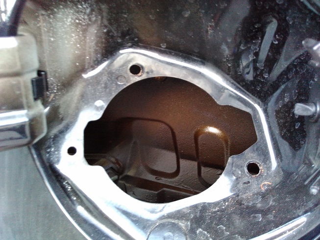
Next I took a look behind the inlet area looking for space of where to fit a junction of the HV wires.

zSnESSd.jpg


http://i.imgur.com/XFhc4OB.jpg

Um96vlV.jpg


From this I'm seeing space behind the inlet if wanting to place the contactor or some kind of junction of the HV wires.

NyDOr9u.jpg


I took out the chademo inlet by loosing the clips using a flat screwdriver.

jDkCQ8p.jpg


Next I worked on recovering wires from the wreck.
I want to reuse the HV wires and BMS wires. Regarding the BMS wiring I could use the electrical diagram over the circuits of which wires does what.

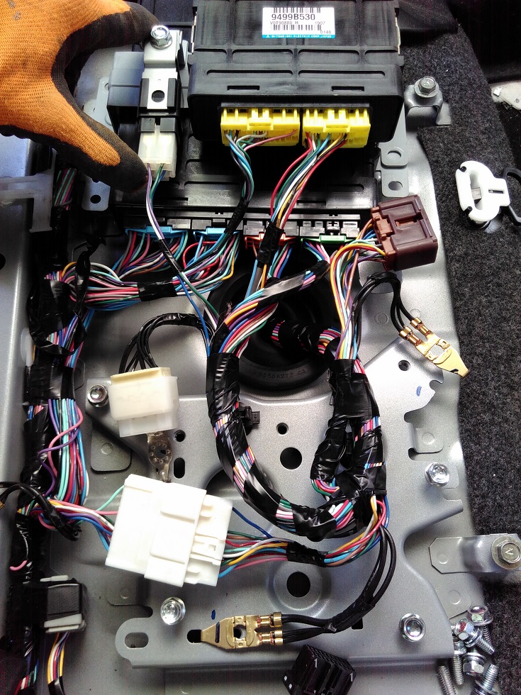
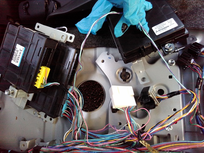
This will be the BMS and wiring on the wreck. I removed the A/C controller at the bottom to get a better overview.

i8MJUOF.jpg


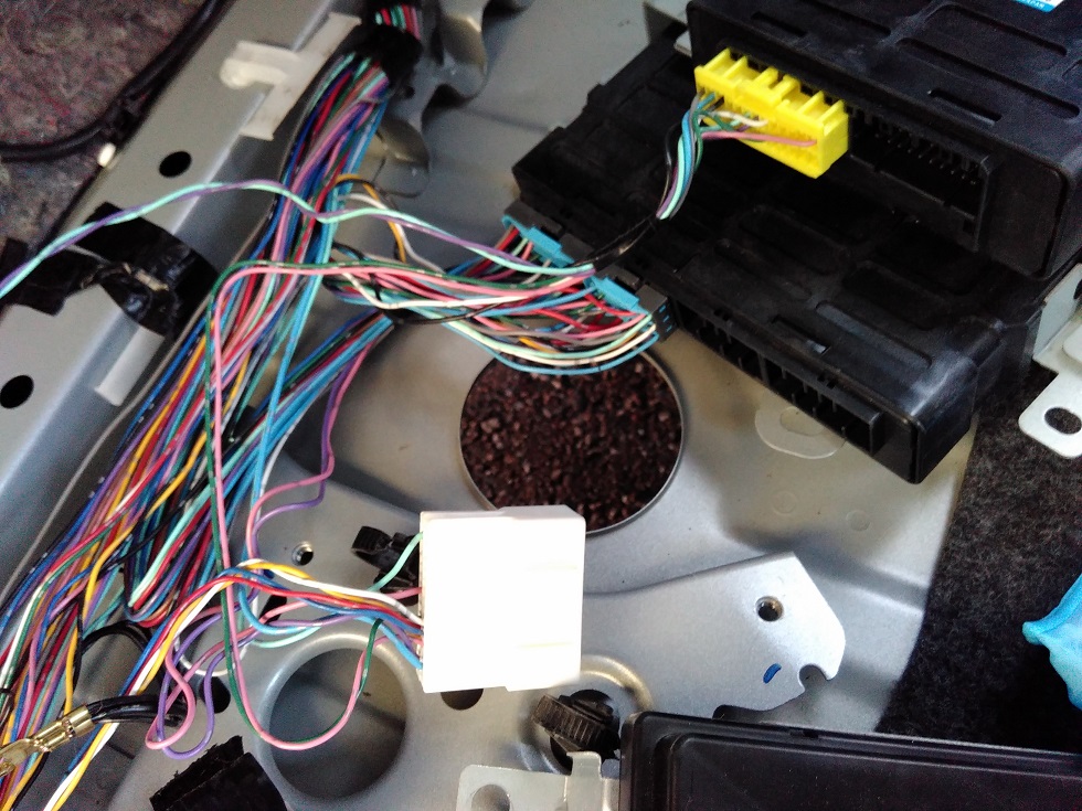
I've made an understanding how the right-hand yellow connector on the BMS is connecting the battery sensors. Anybody who can bring clarity to this? .. wiring diagram would be helpful.
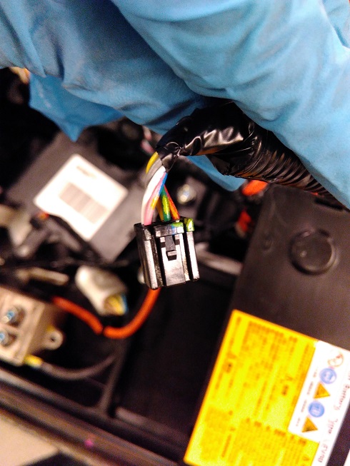
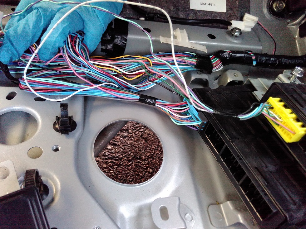
On the left-hand yellow connector it seams there are a bunch of other stuff connected. I'm wondering what each of these wires do and which are needed for the BMS to keep balancing the battery pack. The intend is to have the 2nd BMS continuously balance the 2nd battery, without communicating to the ECU, unless the left-hand yellow connector is taken out of the 1st BMS and inserted into the 2nd BMS. Anybody who can clarify as to whether the left-hand yellow connector can be left out and still having a functional BMS?

Without the wiring diagram I followed up the wires from the left-hand yellow connector to figure out where they are going

VeZ6ItC.jpg


mUR1YWg.jpg


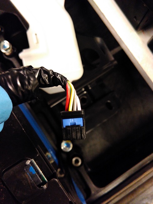
Blue and Grey are routed to the front of the car. The white seams routed directly to the ECU. The others looks less clear as they go in to those junction-connectors near the A/C controller.

kVqp4Bu.jpg


Input and comments are welcome.. and a wiring diagram. :)

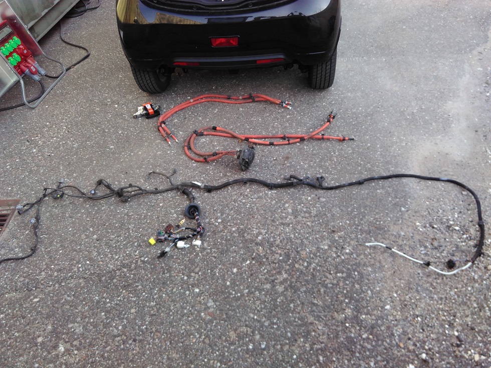
This progress was made over 3 days. After a full day mostly underneath the car I got the BMS & ECU wires and connectors off.. Had to cut most of the ties to release the wires and to keep all the wires in one piece which was the aim. I also got the HV wires from the battery off as well.

VinDl0e.jpg


So next up is
- Clarity on BMS wires: What does the wires of the left connector do?
- Clarity on HV wires from 2nd battery via Chademo HV wires. How and Where?

To be continued.. :)
 
So we pulled it off and got the second pack in the car and connected. Great job. It took lots of preparation and studying wiring diagrams.

In the last few days I studied the manual which I downloaded via this forum under the articles.
I found the diagrams of the BMU (BMS unit) and looked for how to hook up the second BMS from the wreck if possible without disturbing the ecu.

Summery of achievment at this point.
- The ev is now having 2 BMS installed and only one communicating to the ECU. The CAN signals can be switched on so one BMS transmits at a time. And it works - mostly. :)
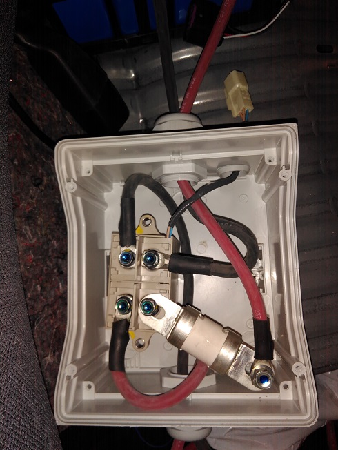
- The ev has an additional contactor and fuse placed inside the cabin below the rear seats to the right (replaced the tire-fix). This is placed inside a box for increased safety.
- As trial the HV wiring is completed by unscrewing the chademo inlet, and plugging a chademo plug into the inlet. The wires from the Chademo plug are routed through ducting below the ev and up underneath the right hand side of the rear seats. At this location there's already a rubber seal which hosts another smaller 2-wire circuit. The chademo and HV wires are packed up tightly up and behind the left rear wheel cover/mud-guard.
- A complete set of wiring is pulled from the wrecked ev and placed underneath the metal covers of the rear seats. The used connectors and wires are sticking out: BMS, bms wiring, contactor, grounding, chademo relay..

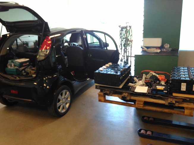
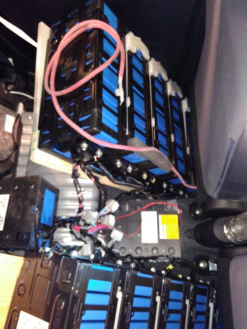
.. and finally we got the second battery pack in the back of the car. Great job everybody. We were 3 guys placing each of the two main 5xLEV50-8 packs at each footwell in the back. They are support by a plate on the back side and leaning down on the "seats". The two LEV50-4 are placed in the center between the two main packs. This design placement worked out well with regards to lenght of the bms wires.

Starting up the EvBatMon or Canion, they are seamingly both able to connect to the main/stock battery below the ev. When flipping the switch which I put on the CAN wires along with two relays this makes the it possible to see the status on either battery, one at a time.

Before connecting the HV wires to the contactor and before even considering starting up the ev I used the monitoring app's to see the Voltage of the second battery pack, in order to match the same voltage by charging the main battery to same level of voltage. I reached a level of 0,3Volts apart and decided to try and connect the contactor and start up.

The ride back from the workshop was easy and indeed used little power.
Tests in time ahead will show more about range increase and other new discoveries.

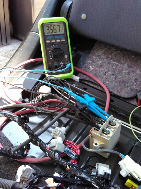
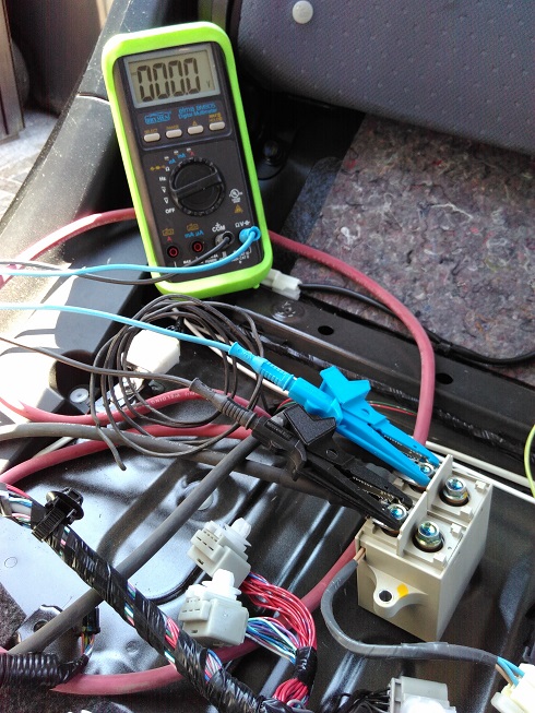
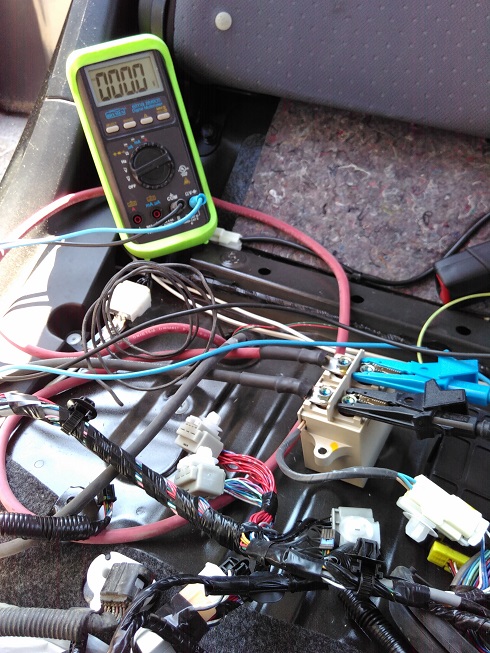
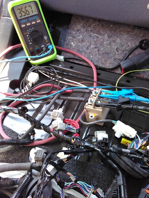
Testing contactor after discovering how the ground-wire to the qc relay was actually activated from the ecu. This caused confusion at first as the QC contact in the main pack wouldnt engage nor the second contactor for the second battery. After more studying of the technical diagram I found which wire to access and so we got the contactors activated and access to the power of the main battery via this second contactor. Huge relief and celebration. :)

Measuring on the side of the contact connected to the Chademo inlet.
ROZ4ly7.jpg


So the contactor is connected in parallel to the main contactor in the battery pack which means this turns on and off as the car is put in "ready" and off.
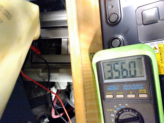
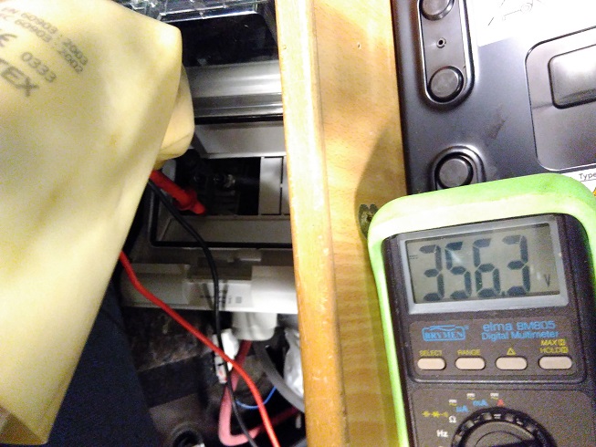
Showing the Voltage of the main battery pack.
AWIkrLL.jpg


bIHtvlT.jpg


Showing the contactor is indeed switched on.
tX96qyN.jpg


Then pulling the ev in to the workshop area and bringing the second battery ready as the preparations of contactor, bms wiring, bmu and CAN signal was complete.

S8Mced2.jpg


The contactor placed in box for safety. The fuse put directly on the contactor in this trial periode. When in regular use a more secure setup is needed.
PGsSoKn.jpg


Batteries placed inside the car and HV wiring between the cell-packs was carried out.

doClPra.jpg


v0VJJIW.jpg


As the main battery had charged to similar Voltage levels as the second battery the HV wires on the second pack was connected to the contactor and contactor was disconnected. This offered the opportunity to have both voltages available on the contactor on either side ready to measure.

Voltage on the main battery below the car.
ps7AWYo.jpg


Voltage on the second battery inside the cabin.
LPgVoi2.jpg


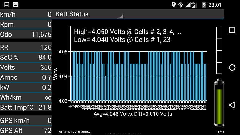
OBD readings of the main battery status

doCN4E1.png


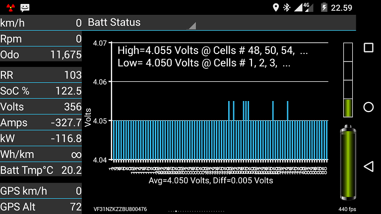
OBD readings of the second battery status

3SmW8hZ.png


Interestingly the Amps and kW seams negative. Unsure what to do about this. Any clue?
 
That is great progress, and thanks for sharing the pictures and details of how you were able to fit the pack into the back seat area.

i would guess that the second pack is entering the circuit in such a way that the current sensor is reading a reverse polarity with respect to the normal direction of current flow, and as a result it produces a negative value.

But there are no "negative" numbers in the digital world, only some sort of two's-complement interpretation of very small or very large values. The regular pack was showing 0.7 Amps, a very small value or nearly zero depending on what loads were active. The same loads were likely active with the second pack but the current sense was opposite direction, so -0.7 A. But the software would interpret this nearly zero negative value using the 2's-complement as a value at nearly full scale, and then set the negative direction bit (regen). The CanIon reads the CAN buss and reports 327.7 A in the regen direction, or the -327.7 that you saw. Power is calculated from VxI, so it is (-) also.

Assume 16-bits with one for direction, leaves 15 bits for value, so values range from 0 to 2^15 =32768 full scale, which reads as 327.7 with a scale factor of 10 mA per bit.

Something is definitely confused since it is showing a SOC of 122.5%...? what does that mean?
A simple schematic diagram of your arrangement might help understand what is happening.
 
Brief update from first trial driving with 2 battery packs.

Driven 178km and CaniOn says 33% remaining on either battery.
Driving conditions: mix of aprox.
48km city trafic (0-50km/h),
100km main road (70-80km/h) and
30km of motorway (95-110km/h).
Temperatur: 15-20degC
Humidity: 55-65%
Altitude: 0-100m, with 5-10 climbs of 4-8%. Each about 500m.
Wind: 10-15 m/s headwind and tailwind on return.
 
Nice. Just about double the range, which is what one would expect. Quite interesting that you were able to get two BMUs to work with one car, but it makes sense (only one at a time with the same PIDs and data close enough to not cause a fault).

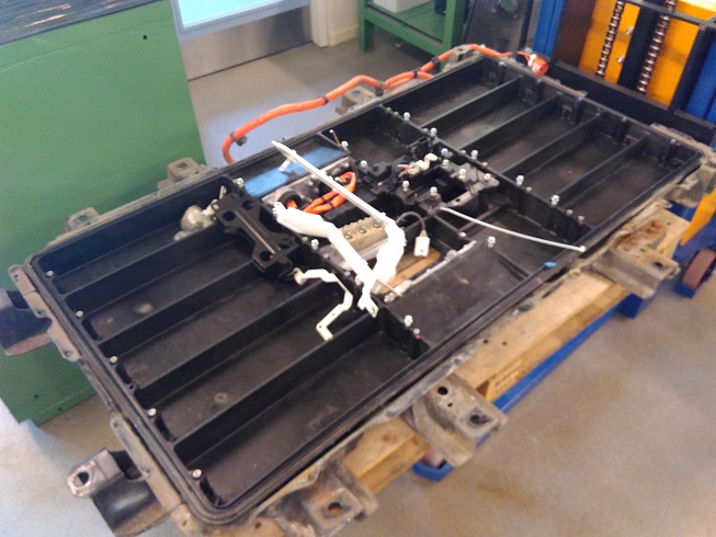
Out of curiosity, how much does the empty battery case weigh?
 
Well done!
Will you be selling the MCU from the crashed car?
Should know this week if it's stopping my Citroen C0 from coming to ready.
 
Hey Dani,

Congratulations on the great work and the photos. I assume you are charging the the 2nd pack with an external charger.

It looks to me if I understand you correctly that you are able to swap the BMS CAN signals from the internal and external pack and read the voltages from either pack. It's good to know that works. For the current I believe there are 2 current sensors somewhere I am not sure of the location.

I would guess that you are missing something that is generating the current value and putting it on the can bus for canion to pick up. I took a look at the diagrams I think you already know about this site:

http://mmc-manuals.ru/manuals/i-miev/online/Service_Manual_2011_2012/2012/index_M1.htm

I was not able to locate anything related to current sensing in there but I might have missed it. If the current sensor is working on the internal pack but not on the external one it might be some signal that is missing in the BMS connector or something missing downstream. If the CMU's also sense current and send it up to the BMU and maybe something is disconnected when you broke up the battery in sections. Did you see any current sensors in the battery ?

Maybe someone else on the forum knows where the current sensors are and how they send data.

What you are doing is really amazing. Please keep us up to date.

BTW

how does the car handle with the extra weight ? It looks like you are trying to get it as low as possible so it should be better then when sia47 did it.


Don.......
 
Don, no reason both packs can't be charged together with the on-board charger. It'll take longer, but should work just fine as the aux. pack's BMS is present for the most part.
 
Hey PV1,

I wonder how it would work. If you have both packs connected during charge. Doesnt the bms taper the charge current as the battery get to full ? how would that work with two packs if the charge state of each one is different ? Maybe the fuller pack would charge the less full one and things would equalize out but i would monitor that closely during charge.

I would worry that if the external pack hit the high voltage limit on the cells and could not control the charger to tell it to taper the charge then the charge current might push the cells over 4.1 volts. Perhaps this would not happen because the packs would equalize but If not it would be a bad situation.

What do you think ?

Don.....
 
The only way that cells in the external pack would go over 4.1 volts is if the external pack is mis-balanced, which would be fixed by the BMU over the longer term. The external pack sees the same voltage as the main pack, so one pack wouldn't be overcharged when they're connected to the same charger. It looks like both packs are balanced, and since both still have functioning BMUs, they should stay balanced. Even still, the cells have headroom and can go to 4.2 volts.

With the relatively tiny size of the on-board charger especially across two packs, the two packs won't become mis-balanced, but if they should, they will auto-equalize. This project isn't much different than how Tesla and Nissan battery packs are constructed with multiple cells in parallel (except they are paralleled at the cell level and this is paralleled at the pack level). Since they are the same size, voltage, and chemistry, the two packs' median voltage will result in the SoC of each pack being very close to each other if not the same. Being that the external pack is connected automatically when the main pack is connected, there shouldn't be an instance when the two packs become severely out of balance with each other unless the external contactor fails to engage or the fuse blows. At this point, the main pack must be brought back to the voltage of the external pack before they are re-connected.

Dani, it may be possible to connect an OBDLink to the external pack's CAN lines and have two instances of CaniOn running at the same time. One monitors the car and the original pack and the other watches the external pack.
 
Hey Dani,

So I had another look at the online wiring diagrams.

In the section:MAIN BATTERY MANAGEMENT SYSTEM

The first diagram shows the current sensors in the battery wired to the BMU.

There are 4 wires RED GREEN WHITE and BLue on pins 31,32,33,42 of one of the yellow BMU connectors. I guess these were not connected in your battery external battery. I believe there are 2 current sensors.

In any case you can also measure the voltage on these pins in the operational car and then play with it to figure it out if you have not already.

CHeers

DOn......
 
I took the pack out of my imiev (with help from friends).

kiev said:
Were the buss bars painted or coated with something--they appear white in the pictures and look like the surface has cracked in some of the bends?

We found ours coated in a grey rubber.

kiev said:
In the third picture of the previous post there is a contactor with red terminal lugs going to the adjacent buss bar--i'm thinking this is the pre-charge resistor connection from the pre-charge contactor to the B+ feed from the pack. Could you measure the value of that resistor?

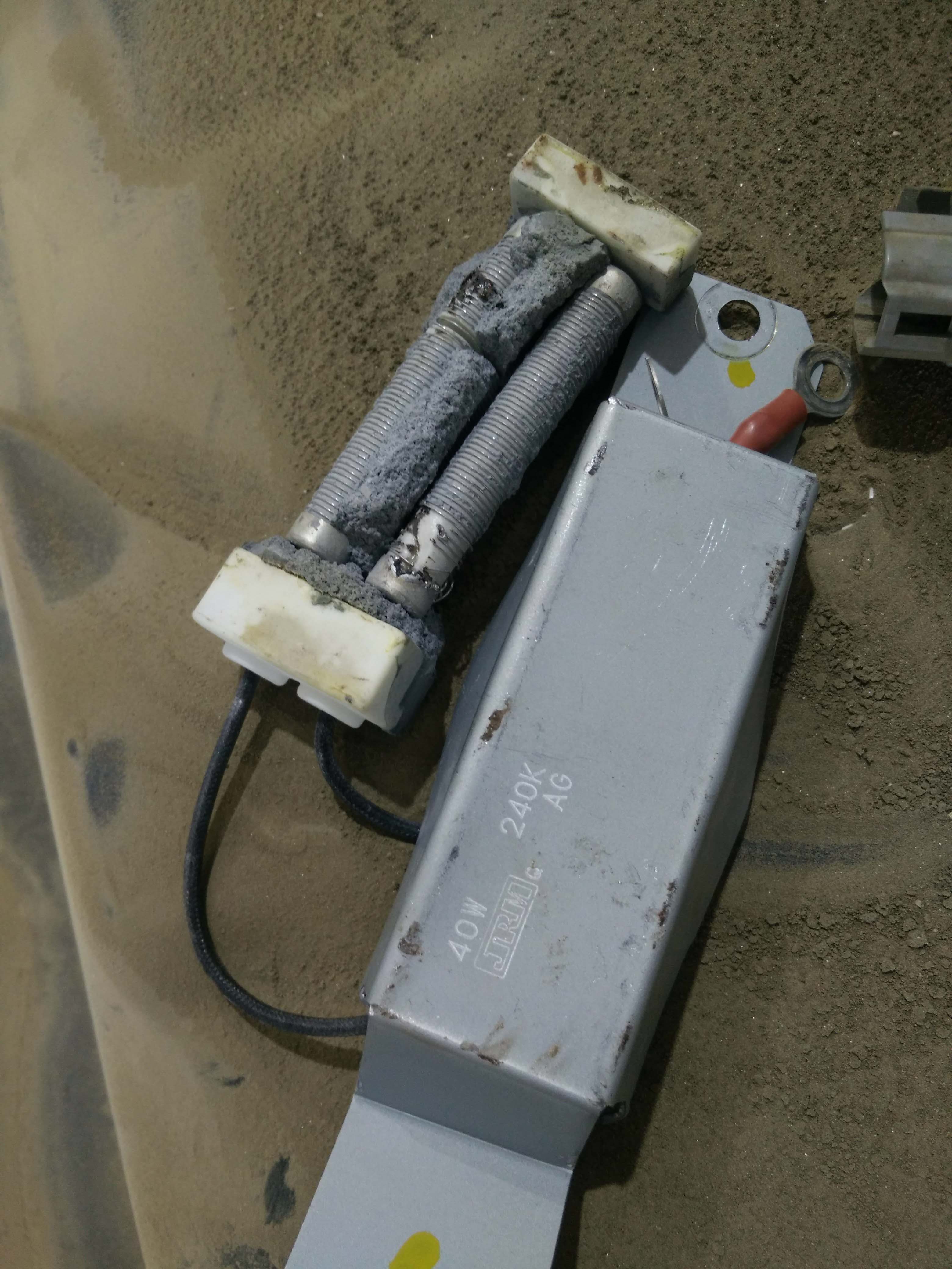
I can't measure ours - it was the faulty part we removed the pack to replace.It's labelled 240KAG 40W "JRH", but 240kΩ on 360V is nowhere near 40W. The part was open circuit so we couldn't measure it's value.

We broke it apart to see what was inside, found burnt wire coil, and found it was made up of two coils in series. Measuring ~90% of one coil we found 9Ω, extrapolating to the full length of both coils it's around 20Ω.
Yv1PkJG.jpg
 
Great job on getting to the resistor, and it looks like your hunch was right that it was damaged.

i posted a link to some datasheets on your thread about the resistor, i think the value is 24. , the "K" is an indicator that it is a 10% tolerance part.

http://myimiev.com/forum/viewtopic.php?f=22&t=4194&p=38001#p38001


[edit] posted some scope traces capturing the precharge current, and some calculations of resistor power load over there also.

The resistor has to dissipate the energy stored in the capacitors over the precharge timeframe.
 
If K is the tolerance I would have thought that would make the value 240 ohms not 24 ?

5400 watts seems like an awfully high surge even for 60ms for a 40 watt resistor.
 
He did mention that one side measured 9 Ohms for part of the undamaged length and estimated two in series would be about 20 Ohms. The gauge of the wire and number of turns seems consistent with the measurement.
 
kiev said:
He did mention that one side measured 9 Ohms for part of the undamaged length and estimated two in series would be about 20 Ohms. The gauge of the wire and number of turns seems consistent with the measurement.

But If it were 240 Ohms, then the power load would be 540 W for about 0.6 seconds to charge the MCU cap.
Yes I saw that part of the resistor measured 9 ohms, but I'm not sure I would automatically assume it was "undamaged". There could potentially have been shorted turns in that half which caused the rest of the resistor overheat as the "normal" high resistance part would take the brunt of the dissipation.

Also 240 is ambiguous - it could be a two prefix + multiplier code for 24 ohms, but its more common for low value large power resistors to use a full value with the tolerance letter in place of the decimal point, which would make it 240 ohms.

If the point of it is to pre-charge the capacitors, 5400 watts for 60ms seems awfully quick not just for stress on the resistor but for the capacitors! 540 watts for 0.6 seconds seems much more reasonable for a "soft start" circuit, especially when you factor in contactor switching times. Most power supply soft start circuits have a charge time of approx one second.

It may well be 24 ohms after all, but if it is, I wonder if it's a part just waiting to fail due to excessive inrush current though a device that should be avoiding just such an inrush... :|

it really would be great if someone with a wrecked pack could measure this resistor to be sure, but I know that's unlikely to happen.
 
Back
Top