Hello coulomb,
Thank you for the prompt answer! I was away for a few days, but will resume testing and eventually pull both charger boards out and inspect them very closely.

Thank you for the prompt answer! I was away for a few days, but will resume testing and eventually pull both charger boards out and inspect them very closely.
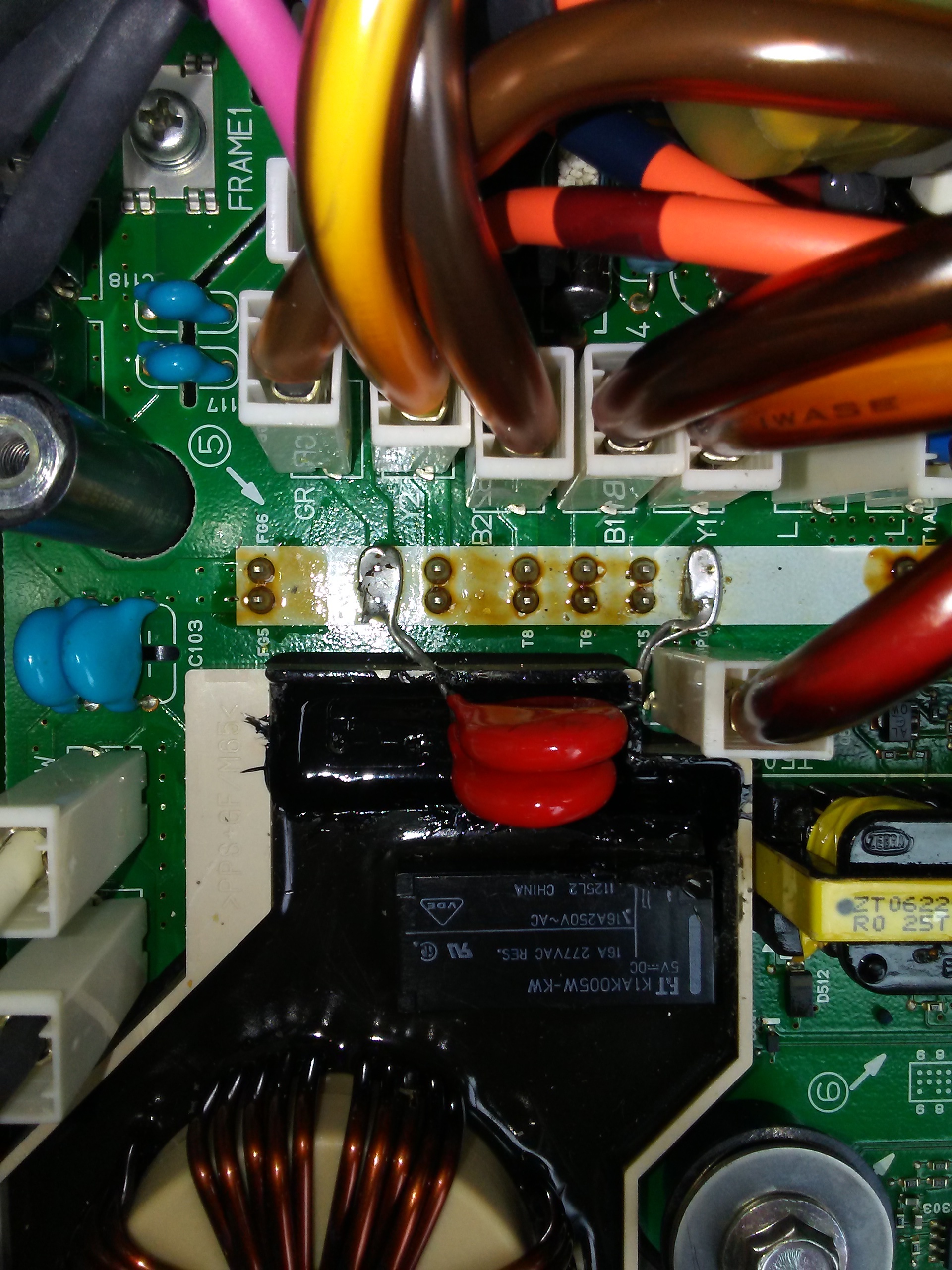
- Yes, as I said - I will test the ceramic caps and that thermal fuse. Thank you kindly for coming across this photo, very handy!
- DTCs... can`t seem to read those with either ELM327, two ELM327 mini, an OBDClick, AutoDia K409, VAG KKL and VCDS... I can`t connect at all to the car (but the devices are fed 12v). Obviously, these are not mine, but the car owner was able to source them from all his acquaintances. I only have an old Delphi (purchased with heavy money for my father`s Citroen), but I can`t find its software anymore ))... Is there any sequence of commands I need to perform before I can successfully connect with any DTC reader? Or does the 2012 Citroen only work with MUT?
- We always pull the driver`s seat plug, it`s not fun being charred from 330v.. and yes, we always disconnected the 12v battery whenever we touched the BCM or ECM.
- Cool thing that it can be removed from the car without draining the coolant, thanks for the tip. Will take pictures with what wires goes where, to not do fireworks afterwards. Very odd that some wires change colors from one place to the other, I have never seen wires crimped in the middle from the factory...
- I have no idea whether the DC-DC charger works (drive battery -> 12v battery), as I have only seen the car with the drive battery depleted. But yes, the motor controller 20A fuse is healthy. Although a terribly bad idea, I might even try and somehow charge the 330v battery myself.. but at this point I have no such charger.. I could feed some HV mosfets (that I obviously need to procure) from an ATX PSU active PFC circuit.. that should be close to 400v, so it`s above 330v. but it`s still very dangerous, I agree.
- OBD-II.. isn`t that supported by the VCDS cable tester? Or by any ELM or OBDClick? Odd that we can`t connect to the car at all... The testers do get voltage, bluetooth connection works, tester light lights up without cable plugged into the car, hand-held devices do power on...


 please